CN110685903A - Hydraulic motor gear pump with impeller pressurizing liquid supply at inlet - Google Patents
Hydraulic motor gear pump with impeller pressurizing liquid supply at inlet Download PDFInfo
- Publication number
- CN110685903A CN110685903A CN201911134321.XA CN201911134321A CN110685903A CN 110685903 A CN110685903 A CN 110685903A CN 201911134321 A CN201911134321 A CN 201911134321A CN 110685903 A CN110685903 A CN 110685903A
- Authority
- CN
- China
- Prior art keywords
- oil
- impeller
- gear pump
- end cover
- main shaft
- Prior art date
- Legal status (The legal status is an assumption and is not a legal conclusion. Google has not performed a legal analysis and makes no representation as to the accuracy of the status listed.)
- Granted
Links
- 239000007788 liquid Substances 0.000 title claims abstract description 12
- 238000007789 sealing Methods 0.000 claims abstract description 12
- 210000004907 gland Anatomy 0.000 claims description 7
- 230000000694 effects Effects 0.000 claims description 3
- 239000003921 oil Substances 0.000 description 56
- 238000001816 cooling Methods 0.000 description 6
- 238000010521 absorption reaction Methods 0.000 description 5
- 238000000034 method Methods 0.000 description 5
- 239000010720 hydraulic oil Substances 0.000 description 2
- 238000010586 diagram Methods 0.000 description 1
- 230000017525 heat dissipation Effects 0.000 description 1
- 230000010354 integration Effects 0.000 description 1
Images


Classifications
-
- F—MECHANICAL ENGINEERING; LIGHTING; HEATING; WEAPONS; BLASTING
- F04—POSITIVE - DISPLACEMENT MACHINES FOR LIQUIDS; PUMPS FOR LIQUIDS OR ELASTIC FLUIDS
- F04C—ROTARY-PISTON, OR OSCILLATING-PISTON, POSITIVE-DISPLACEMENT MACHINES FOR LIQUIDS; ROTARY-PISTON, OR OSCILLATING-PISTON, POSITIVE-DISPLACEMENT PUMPS
- F04C11/00—Combinations of two or more machines or pumps, each being of rotary-piston or oscillating-piston type; Pumping installations
-
- F—MECHANICAL ENGINEERING; LIGHTING; HEATING; WEAPONS; BLASTING
- F04—POSITIVE - DISPLACEMENT MACHINES FOR LIQUIDS; PUMPS FOR LIQUIDS OR ELASTIC FLUIDS
- F04B—POSITIVE-DISPLACEMENT MACHINES FOR LIQUIDS; PUMPS
- F04B23/00—Pumping installations or systems
- F04B23/04—Combinations of two or more pumps
- F04B23/08—Combinations of two or more pumps the pumps being of different types
- F04B23/12—Combinations of two or more pumps the pumps being of different types at least one pump being of the rotary-piston positive-displacement type
-
- F—MECHANICAL ENGINEERING; LIGHTING; HEATING; WEAPONS; BLASTING
- F04—POSITIVE - DISPLACEMENT MACHINES FOR LIQUIDS; PUMPS FOR LIQUIDS OR ELASTIC FLUIDS
- F04C—ROTARY-PISTON, OR OSCILLATING-PISTON, POSITIVE-DISPLACEMENT MACHINES FOR LIQUIDS; ROTARY-PISTON, OR OSCILLATING-PISTON, POSITIVE-DISPLACEMENT PUMPS
- F04C15/00—Component parts, details or accessories of machines, pumps or pumping installations, not provided for in groups F04C2/00 - F04C14/00
- F04C15/0003—Sealing arrangements in rotary-piston machines or pumps
- F04C15/0023—Axial sealings for working fluid
-
- F—MECHANICAL ENGINEERING; LIGHTING; HEATING; WEAPONS; BLASTING
- F04—POSITIVE - DISPLACEMENT MACHINES FOR LIQUIDS; PUMPS FOR LIQUIDS OR ELASTIC FLUIDS
- F04C—ROTARY-PISTON, OR OSCILLATING-PISTON, POSITIVE-DISPLACEMENT MACHINES FOR LIQUIDS; ROTARY-PISTON, OR OSCILLATING-PISTON, POSITIVE-DISPLACEMENT PUMPS
- F04C15/00—Component parts, details or accessories of machines, pumps or pumping installations, not provided for in groups F04C2/00 - F04C14/00
- F04C15/0096—Heating; Cooling
-
- F—MECHANICAL ENGINEERING; LIGHTING; HEATING; WEAPONS; BLASTING
- F04—POSITIVE - DISPLACEMENT MACHINES FOR LIQUIDS; PUMPS FOR LIQUIDS OR ELASTIC FLUIDS
- F04C—ROTARY-PISTON, OR OSCILLATING-PISTON, POSITIVE-DISPLACEMENT MACHINES FOR LIQUIDS; ROTARY-PISTON, OR OSCILLATING-PISTON, POSITIVE-DISPLACEMENT PUMPS
- F04C15/00—Component parts, details or accessories of machines, pumps or pumping installations, not provided for in groups F04C2/00 - F04C14/00
- F04C15/06—Arrangements for admission or discharge of the working fluid, e.g. constructional features of the inlet or outlet
- F04C15/062—Arrangements for supercharging the working space
-
- F—MECHANICAL ENGINEERING; LIGHTING; HEATING; WEAPONS; BLASTING
- F04—POSITIVE - DISPLACEMENT MACHINES FOR LIQUIDS; PUMPS FOR LIQUIDS OR ELASTIC FLUIDS
- F04C—ROTARY-PISTON, OR OSCILLATING-PISTON, POSITIVE-DISPLACEMENT MACHINES FOR LIQUIDS; ROTARY-PISTON, OR OSCILLATING-PISTON, POSITIVE-DISPLACEMENT PUMPS
- F04C2240/00—Components
- F04C2240/30—Casings or housings
Landscapes
- Engineering & Computer Science (AREA)
- Mechanical Engineering (AREA)
- General Engineering & Computer Science (AREA)
- Chemical & Material Sciences (AREA)
- Combustion & Propulsion (AREA)
- Rotary Pumps (AREA)
Abstract
Description
技术领域technical field
本发明涉及液压电机泵,尤其涉及进口带叶轮增压供液的液压电机齿轮泵。The invention relates to a hydraulic motor pump, in particular to a hydraulic motor gear pump with an imported impeller for pressurizing and supplying liquid.
背景技术Background technique
传统液压油泵组体积大,噪声高,存在外泄漏,人机不友好等,基于此,液压电机泵的设计构想应运而生,其核心思想便是将驱动电机与液压泵一体化集成,去除联轴器,油冷代替风扇冷却电机,具有结构紧凑、噪声低、散热效果好、人机友好等优点,国外已有成熟的系列化电机泵产品,然而液压泵吸油先天不足,且相当严重,高转速时,液压泵效率尤其低下,如此液压电机泵的效率并不高,甚至低于传统液压油泵组。The traditional hydraulic oil pump set is large in size, high in noise, has external leakage, and is not friendly to human and machine. Based on this, the design concept of the hydraulic motor pump came into being. The core idea is to integrate the drive motor and the hydraulic pump, and remove the Shaft, oil cooling instead of fan cooling motor, has the advantages of compact structure, low noise, good heat dissipation effect, human-machine friendly, etc. There are mature series of motor pump products abroad, but hydraulic pump oil suction is inherently insufficient, and it is quite serious, high speed The efficiency of the hydraulic pump is particularly low, so the efficiency of the hydraulic motor pump is not high, even lower than that of the traditional hydraulic oil pump set.
发明内容SUMMARY OF THE INVENTION
本发明的目的是提供一种进口带叶轮增压供液的液压电机齿轮泵。The purpose of the present invention is to provide a hydraulic motor gear pump with an imported impeller for pressurizing and supplying liquid.
本发明是进口带叶轮增压供液的液压电机齿轮泵,包括壳体1、放气孔螺堵2、前端盖3、齿轮泵组4、第一平键5、出油口压盖6、主轴7、第一轴承8、第一密封件9、电机转子10、电机定子11、泄油口螺堵12、密封垫13、内端盖14、后端盖15、叶轮16、第二平键17、螺母18、第二轴承19、第二密封件20、接线盒组件21,电机转子10通过过盈配合安装在主轴7上,以第一轴承8和第二轴承19支撑在壳体1上,齿轮组4安装在前端盖3上,通过第一平键5与主轴7相连,叶轮16设置在后端盖15和内端盖14之间,并用第二平键17与主轴7连接,主轴7两端由第一密封件9和第二密封件20密封。The present invention is an imported hydraulic motor gear pump with impeller pressurized liquid supply, including a
本发明的有益之处是:The benefits of the present invention are:
(1)所述的进口带叶轮增压供液的液压电机齿轮泵,是电机、离心泵叶轮和齿轮泵的一体化集成体,进油口设置叶轮,油液经增压后到达齿轮泵吸油口,很好的改善了齿轮泵的吸油不足问题,特别在较高转速时,齿轮泵吸油效率的提升更为明显,同时也避免了因吸油不足产生的气穴噪声;(1) The hydraulic motor gear pump with impeller pressurized liquid supply at the inlet is an integrated body of motor, centrifugal pump impeller and gear pump. The oil inlet is provided with an impeller, and the oil is pressurized and reaches the gear pump for oil absorption. It improves the problem of insufficient oil absorption of the gear pump, especially at a higher speed, the improvement of the oil absorption efficiency of the gear pump is more obvious, and at the same time, the cavitation noise caused by insufficient oil absorption is avoided;
(2)所述的进口带叶轮增压供液的液压电机齿轮泵,主轴两端采用非接触式甩油密封,防止油液进入电机定子和转子之间的气隙中,避免了粘性摩擦损耗,电机泵效率进一步提高;(2) For the imported hydraulic motor gear pump with impeller pressurized liquid supply, both ends of the main shaft are sealed with non-contact oil rejection to prevent oil from entering the air gap between the motor stator and rotor, and avoid viscous friction loss , the motor pump efficiency is further improved;
(3)所述的进口带叶轮增压供液的液压电机齿轮泵,工作过程中提供高压油的同时,也将自身产生的热量带出,很好的代替了风扇冷却,噪声大幅度降低,结构也更加紧凑。(3) The imported hydraulic motor gear pump with impeller pressurized liquid supply, while supplying high-pressure oil during the working process, also takes out the heat generated by itself, which is a good substitute for fan cooling, and the noise is greatly reduced. The structure is also more compact.
附图说明Description of drawings
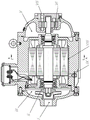
图1为本发明的结构原理图,图2主轴的主视图,图3前端盖的主视图,图4为电机泵的主视图,图5为图4的A-A视图,附图标记及对应名称为:壳体1,放气孔螺堵2,前端盖3,放气孔3a,卸荷槽3b,月牙板3c,齿轮泵吸油口VI,齿轮组4,第一平键5,出油口压盖6,主轴7,外螺纹7a,第二平键槽7b,第二油槽7c,第一油槽7d,第一平键槽7c,第一轴承8,第一密封件9,电机转子10,电机定子11,泄油口螺堵12,密封垫13,内端盖14,后端盖15,叶轮16,第二平键17,螺母18,第二轴承19,第二密封件20,接线盒组件21,进油口I,内腔II,电机泵后腔III,流道IV,电机泵前腔V,排油口VII,泄油槽VIII,泄油口IX。Fig. 1 is a structural principle diagram of the present invention, Fig. 2 is a front view of a main shaft, Fig. 3 is a front view of a front end cover, Fig. 4 is a front view of a motor pump, Fig. 5 is A-A view of Fig. 4, the reference signs and corresponding names are :
具体实施方式Detailed ways
如图1~图5所示,本发明是进口带叶轮增压供液的液压电机齿轮泵,包括壳体1、放气孔螺堵2、前端盖3、齿轮泵组4、第一平键5、出油口压盖6、主轴7、第一轴承8、第一密封件9、电机转子10、电机定子11、泄油口螺堵12、密封垫13、内端盖14、后端盖15、叶轮16、第二平键17、螺母18、第二轴承19、第二密封件20、接线盒组件21,电机转子10通过过盈配合安装在主轴7上,以第一轴承8和第二轴承19支撑在壳体1上,齿轮组4安装在前端盖3上,通过第一平键5与主轴7相连,叶轮16设置在后端盖15和内端盖14之间,并用第二平键17与主轴7连接,主轴7两端由第一密封件9和第二密封件20密封。As shown in Figures 1 to 5, the present invention is an imported hydraulic motor gear pump with impeller pressurized and supplied liquid, including a
本发明的进口带叶轮增压供液的液压电机齿轮泵,是一种将电机、离心泵叶轮和齿轮泵的一体化集成,在进油口I设置叶轮16,油液经增压后到达齿轮泵吸油口,很好的改善了齿轮泵的吸油不足问题,特别在较高转速时,齿轮泵吸油效率的提升更为明显,同时也避免了因吸油不足产生的气穴噪声,壳体1上开设的通道IV既是通油流道,也是冷却流道,叶轮16和齿轮组4均由平键与主轴7连接驱动,主轴7两端由第一密封件9和第二密封件20密封,防止油液进入电机定子11和转子10之间的气隙中,避免了粘性摩擦损耗,电机泵效率进一步提高,本发明在工作过程中提供高压油的同时,也将自身产生的热量带出,很好的代替了风扇冷却,噪声大幅度降低,结构也更加紧凑。The imported hydraulic motor gear pump with impeller pressurized liquid supply of the present invention is a kind of integrated integration of motor, centrifugal pump impeller and gear pump, and an impeller 16 is arranged at the oil inlet I, and the oil reaches the gear after being pressurized. The pump suction port improves the problem of insufficient oil suction of the gear pump. Especially at higher speeds, the oil suction efficiency of the gear pump is improved more obviously, and at the same time, the cavitation noise caused by insufficient oil suction is avoided. The opened channel IV is not only an oil channel, but also a cooling channel. The impeller 16 and the gear set 4 are connected to the
以下结合附图对本发明的原理和特征进行描述,所举实例只用于解释本发明,并非用于限定本发明的范围。The principles and features of the present invention will be described below with reference to the accompanying drawings. The examples are only used to explain the present invention, but not to limit the scope of the present invention.
如图1~图5所示,本发明是进口带叶轮增压供液的液压电机齿轮泵,该电机泵包括壳体1、放气孔螺堵2、前端盖3、齿轮泵组4、第一平键5、出油口压盖6、主轴7、第一轴承8、第一密封件9、电机转子10、电机定子11、泄油口螺堵12、密封垫13、内端盖14、后端盖15、叶轮16、第二平键17、螺母18、第二轴承19、第二密封件20、接线盒组件21,其中电机转子10通过过盈配合安装在主轴7上,以第一轴承8和第二轴承19支撑在壳体1上,齿轮组4安装在前端盖3上,通过第一平键5与主轴7相连,叶轮16设置在后端盖15和内端盖14之间,并用第二平键17与主轴7连接,主轴7两端由第一密封件9和第二密封件20密封。As shown in Figures 1 to 5, the present invention is an imported hydraulic motor gear pump with impeller pressurized liquid supply. The motor pump includes a
如图1、图2所示,所述主轴7上设有外螺纹7a、第二平键槽7b、第二油槽7c、第一油槽7d、第一平键槽7c,其中第一油槽7d和第二油槽7c分别对应第一密封件9和第二密封件20,构成非接触式甩油密封结构,起到密封效果。As shown in Figures 1 and 2, the
如图1、图3所示,所述前端盖3上设有放气孔3a、卸荷槽3b、月牙板3c、齿轮泵吸油口VI,其中月牙板3c位于齿轮组4之间,用于隔开高低压腔。As shown in FIG. 1 and FIG. 3 , the front end cover 3 is provided with a vent hole 3a, an unloading groove 3b, a crescent plate 3c, and a gear pump oil suction port VI, wherein the crescent plate 3c is located between the gear sets 4 and is used to isolate Open high and low pressure chambers.
如图1、图4、图5所示,所述后端盖15上的进油口I与叶轮16的内腔II、电机泵后腔III、壳体1上的流道IV以及电机泵前腔V沟通,构成齿轮泵吸油路,油液经齿轮泵增压后由出油口压盖6上的排油口VII排出,泄油槽VIII和泄油口IX用于排出从第一密封件9和第二密封件20的渗漏的油液。As shown in Figures 1, 4 and 5, the oil inlet I on the rear end cover 15 and the inner cavity II of the impeller 16, the rear cavity III of the motor pump, the flow channel IV on the
如图1、图4、图5所示,所述的进油口I正对叶轮16的内腔II,油液经叶轮16增压后射向电机泵后腔III,随后进入流道IV中,其中流道IV为4条,均布在壳体1上。As shown in Fig. 1, Fig. 4, Fig. 5, the oil inlet I is facing the inner cavity II of the impeller 16, and the oil is pressurized by the impeller 16 and shoots into the rear cavity III of the motor pump, and then enters the flow channel IV , in which there are 4 flow channels IV, which are evenly distributed on the
本发明的工作过程如下:电机泵工作之前,内部先注入油液,待电机泵内部气体完全排出后,给定子线圈11通电,转子10在电磁力矩的驱动下带动电机中心轴7做旋转运动,油液经叶轮16增压后到达齿轮泵吸油口VI,齿轮组4完成吸油和排油,在此过程中,油液带出电机泵产生的热量,完成电机泵冷却。The working process of the present invention is as follows: before the motor pump works, oil is injected into the interior, and after the gas inside the motor pump is completely discharged, the
Claims (5)
Priority Applications (1)
| Application Number | Priority Date | Filing Date | Title |
|---|---|---|---|
| CN201911134321.XA CN110685903B (en) | 2019-11-19 | 2019-11-19 | Imported hydraulic motor gear pump with impeller pressurized liquid supply |
Applications Claiming Priority (1)
| Application Number | Priority Date | Filing Date | Title |
|---|---|---|---|
| CN201911134321.XA CN110685903B (en) | 2019-11-19 | 2019-11-19 | Imported hydraulic motor gear pump with impeller pressurized liquid supply |
Publications (2)
| Publication Number | Publication Date |
|---|---|
| CN110685903A true CN110685903A (en) | 2020-01-14 |
| CN110685903B CN110685903B (en) | 2021-04-13 |
Family
ID=69117689
Family Applications (1)
| Application Number | Title | Priority Date | Filing Date |
|---|---|---|---|
| CN201911134321.XA Active CN110685903B (en) | 2019-11-19 | 2019-11-19 | Imported hydraulic motor gear pump with impeller pressurized liquid supply |
Country Status (1)
| Country | Link |
|---|---|
| CN (1) | CN110685903B (en) |
Cited By (5)
| Publication number | Priority date | Publication date | Assignee | Title |
|---|---|---|---|---|
| CN113236455A (en) * | 2021-05-25 | 2021-08-10 | 南京航空航天大学 | High-power-density electric fuel pump for multi-electric aviation auxiliary power device |
| CN114962206A (en) * | 2022-06-09 | 2022-08-30 | 湖南高创翔宇科技有限公司 | Graded pressurizing fuel pump |
| CN115234485A (en) * | 2022-06-10 | 2022-10-25 | 哈尔滨理工大学 | A gear pump with an axial booster impeller |
| CN117028247A (en) * | 2023-09-21 | 2023-11-10 | 广西柳工机械股份有限公司 | Gear pump oil suction system and construction machinery |
| CN118775252A (en) * | 2024-08-06 | 2024-10-15 | 哈尔滨工业大学 | An adjustable self-cooling outer rotor electric pump |
Citations (8)
| Publication number | Priority date | Publication date | Assignee | Title |
|---|---|---|---|---|
| CN2117479U (en) * | 1992-03-25 | 1992-09-30 | 吉林省锻压设备厂 | Vacuum oil drain pump |
| JPH08219077A (en) * | 1995-02-13 | 1996-08-27 | Ebara Corp | All-round pump |
| CN2427662Y (en) * | 2000-05-12 | 2001-04-25 | 西南交通大学 | Energy-saving type integrated hydraulic source |
| CN1928364A (en) * | 2006-08-15 | 2007-03-14 | 兰州理工大学 | Hydraulic engine gear pump |
| CN103047134A (en) * | 2013-01-24 | 2013-04-17 | 兰州理工大学 | Non-oil-immersed air gap type hydraulic motor vane pump |
| CN104265628A (en) * | 2014-09-11 | 2015-01-07 | 中山市罗顿五金机械有限公司 | Electric hydraulic power device |
| CN106357040A (en) * | 2016-10-08 | 2017-01-25 | 珠海格力电器股份有限公司 | Oil-submersible pump |
| CN107091238A (en) * | 2017-06-16 | 2017-08-25 | 北京富特盘式电机有限公司 | transformer axial-flow pump |
-
2019
- 2019-11-19 CN CN201911134321.XA patent/CN110685903B/en active Active
Patent Citations (8)
| Publication number | Priority date | Publication date | Assignee | Title |
|---|---|---|---|---|
| CN2117479U (en) * | 1992-03-25 | 1992-09-30 | 吉林省锻压设备厂 | Vacuum oil drain pump |
| JPH08219077A (en) * | 1995-02-13 | 1996-08-27 | Ebara Corp | All-round pump |
| CN2427662Y (en) * | 2000-05-12 | 2001-04-25 | 西南交通大学 | Energy-saving type integrated hydraulic source |
| CN1928364A (en) * | 2006-08-15 | 2007-03-14 | 兰州理工大学 | Hydraulic engine gear pump |
| CN103047134A (en) * | 2013-01-24 | 2013-04-17 | 兰州理工大学 | Non-oil-immersed air gap type hydraulic motor vane pump |
| CN104265628A (en) * | 2014-09-11 | 2015-01-07 | 中山市罗顿五金机械有限公司 | Electric hydraulic power device |
| CN106357040A (en) * | 2016-10-08 | 2017-01-25 | 珠海格力电器股份有限公司 | Oil-submersible pump |
| CN107091238A (en) * | 2017-06-16 | 2017-08-25 | 北京富特盘式电机有限公司 | transformer axial-flow pump |
Cited By (6)
| Publication number | Priority date | Publication date | Assignee | Title |
|---|---|---|---|---|
| CN113236455A (en) * | 2021-05-25 | 2021-08-10 | 南京航空航天大学 | High-power-density electric fuel pump for multi-electric aviation auxiliary power device |
| CN113236455B (en) * | 2021-05-25 | 2022-07-12 | 南京航空航天大学 | High-power-density electric fuel pump for multi-electric aviation auxiliary power device |
| CN114962206A (en) * | 2022-06-09 | 2022-08-30 | 湖南高创翔宇科技有限公司 | Graded pressurizing fuel pump |
| CN115234485A (en) * | 2022-06-10 | 2022-10-25 | 哈尔滨理工大学 | A gear pump with an axial booster impeller |
| CN117028247A (en) * | 2023-09-21 | 2023-11-10 | 广西柳工机械股份有限公司 | Gear pump oil suction system and construction machinery |
| CN118775252A (en) * | 2024-08-06 | 2024-10-15 | 哈尔滨工业大学 | An adjustable self-cooling outer rotor electric pump |
Also Published As
| Publication number | Publication date |
|---|---|
| CN110685903B (en) | 2021-04-13 |
Similar Documents
| Publication | Publication Date | Title |
|---|---|---|
| CN110685903B (en) | Imported hydraulic motor gear pump with impeller pressurized liquid supply | |
| CN101255868B (en) | Motor built-in vane pump | |
| CN103047134B (en) | A kind of air gap non-oil-immersed type blade pump for hydraulic engine | |
| CN109458328B (en) | Four-quadrant operation hydraulic motor pump | |
| CN101603536B (en) | Electric vacuum pump for automobile | |
| CN103195745B (en) | A kind of cooling waterpump of new-energy automobile | |
| CN206035814U (en) | Supplementary vacuum pump | |
| CN102135104A (en) | Turbo compressor | |
| CN204126888U (en) | A kind of hydraulic engine gear pump | |
| CN210509604U (en) | High-pressure relief detachable multi-stage centrifugal submersible pump | |
| CN224229015U (en) | Hydraulic power source, hydraulic system and working machine | |
| CN203822710U (en) | Water cooling liquid pump | |
| CN110469502A (en) | A kind of non-oil-immersed type inside engaged gear electric-motor pump of air gap | |
| CN110500257A (en) | An air-gap non-oil-immersed axial piston motor pump | |
| CN113107863A (en) | Water-cooling efficient multistage pump | |
| CN116792322B (en) | Intelligent double-drive pump and water supply system | |
| CN2937559Y (en) | A hydraulic motor vane pump | |
| CN102628435A (en) | Hydraulic power unit including centrifugal pump and vane pump in motor | |
| CN100491730C (en) | Hydraulic motor vane pump with orifice centrifugal auxiliary pump | |
| CN204126908U (en) | A kind of blade pump for hydraulic engine | |
| CN200989300Y (en) | Hydraulic electric machine internal engaging gear pump | |
| CN210371202U (en) | Water flow internal circulation water pump | |
| CN107876805A (en) | A kind of permanent magnet synchronization motor spindle | |
| CN112283108A (en) | An external rotor rotary vane vacuum pump directly driven by a permanent magnet synchronous motor | |
| CN1928364A (en) | Hydraulic engine gear pump |
Legal Events
| Date | Code | Title | Description |
|---|---|---|---|
| PB01 | Publication | ||
| PB01 | Publication | ||
| SE01 | Entry into force of request for substantive examination | ||
| SE01 | Entry into force of request for substantive examination | ||
| GR01 | Patent grant | ||
| GR01 | Patent grant |