CN110685130A - Clothes-horse and airing machine - Google Patents
Clothes-horse and airing machine Download PDFInfo
- Publication number
- CN110685130A CN110685130A CN201810731248.3A CN201810731248A CN110685130A CN 110685130 A CN110685130 A CN 110685130A CN 201810731248 A CN201810731248 A CN 201810731248A CN 110685130 A CN110685130 A CN 110685130A
- Authority
- CN
- China
- Prior art keywords
- clothes
- sliding
- rod
- hanging
- sliding rod
- Prior art date
- Legal status (The legal status is an assumption and is not a legal conclusion. Google has not performed a legal analysis and makes no representation as to the accuracy of the status listed.)
- Pending
Links
Images


Classifications
-
- D—TEXTILES; PAPER
- D06—TREATMENT OF TEXTILES OR THE LIKE; LAUNDERING; FLEXIBLE MATERIALS NOT OTHERWISE PROVIDED FOR
- D06F—LAUNDERING, DRYING, IRONING, PRESSING OR FOLDING TEXTILE ARTICLES
- D06F57/00—Supporting means, other than simple clothes-lines, for linen or garments to be dried or aired
Landscapes
- Engineering & Computer Science (AREA)
- Textile Engineering (AREA)
- Holders For Apparel And Elements Relating To Apparel (AREA)
Abstract
本发明涉及一种晾衣杆及晾衣机。晾衣杆包括衣杆本体、滑动杆以及固定挂衣夹,所述衣杆本体上设有滑动部,所述滑动部沿所述衣杆本体的轴向方向设置并贯穿所述衣杆本体轴向方向的两端,所述滑动杆上设有与所述滑动部对应的滑动配合部,所述滑动杆在所述滑动配合部处与所述衣杆本体滑动连接,所述固定挂衣夹设置在所述滑动杆上。晾衣机包括安装主架以及所述的晾衣杆,所述晾衣杆与所述安装主架连接。晾衣杆及晾衣机装拆方便、快速,操作效率高。
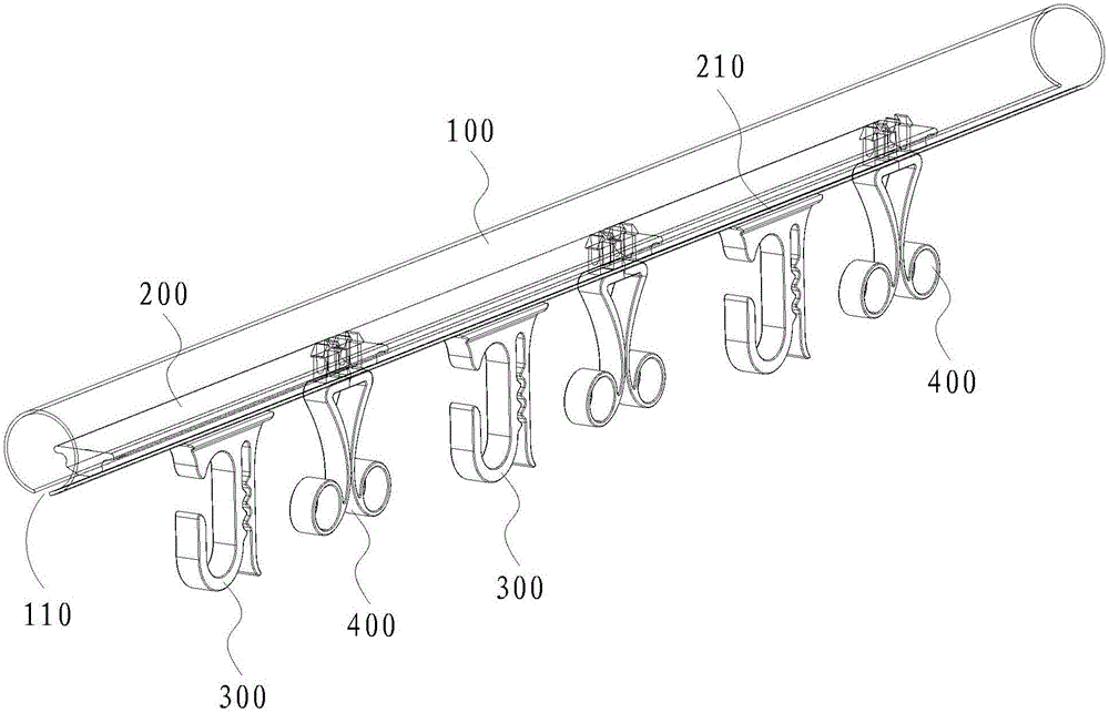
The invention relates to a clothes drying rod and a clothes drying machine. The clothes drying rod includes a clothes rod body, a sliding rod and a fixed clothes hanger. The clothes rod body is provided with a sliding part, and the sliding part is arranged along the axial direction of the clothes rod body and penetrates the axis of the clothes rod body. At both ends of the direction, the sliding rod is provided with a sliding fitting part corresponding to the sliding part, the sliding rod is slidably connected with the clothes rod body at the sliding fitting part, and the fixed clothes hanger arranged on the sliding rod. The clothes drying machine includes an installation main frame and the clothes drying rod, and the clothes drying rod is connected with the installation main frame. The clothes drying rod and the clothes drying machine are easy to assemble and disassemble, and the operation efficiency is high.
Description
技术领域technical field
本发明涉及晾晒设备技术领域,特别是涉及一种晾衣杆及晾衣机。The invention relates to the technical field of drying equipment, in particular to a clothes drying rod and a clothes drying machine.
背景技术Background technique
在晾晒机中,一般通过晾衣杆实现挂衣功能。传统的晾衣杆结构,主要是采用铝拉材一体成型,然后再在该铝拉材上进行二次冲挂衣孔,在挂衣孔的边缘处安装塑料封边件进行封边。采用上述结构,由于挂衣孔的孔数较多,工厂装拆塑料封边件时操作效率低,晾衣服次数多后塑料封边件容易损坏或脱落,从而容易造成衣架刮花,不利于保护衣架。In the drying machine, the clothes hanging function is generally realized by the clothes drying rod. The traditional clothes drying rod structure is mainly made of aluminum drawing material to be integrally formed, and then the clothes hanging holes are punched on the aluminum drawing material for a second time, and a plastic edge sealing piece is installed at the edge of the clothes hanging hole for edge sealing. With the above structure, due to the large number of holes in the clothes hanging holes, the factory has low operation efficiency when assembling and disassembling the plastic edge sealing parts, and the plastic edge sealing parts are easily damaged or fallen off after many times of drying clothes, which is easy to cause scratches on the hanger, which is not conducive to protection. Coat hanger.
发明内容SUMMARY OF THE INVENTION
基于此,有必要提供一种晾衣杆及晾衣机,该晾衣杆及晾衣机装拆方便、快速,操作效率高。Based on this, it is necessary to provide a clothes drying rod and a clothes drying machine, which are convenient and quick to assemble and disassemble, and have high operation efficiency.
其技术方案如下:Its technical solutions are as follows:
一种晾衣杆,包括衣杆本体、滑动杆以及固定挂衣夹,所述衣杆本体上设有滑动部,所述滑动部沿所述衣杆本体的轴向方向设置并贯穿所述衣杆本体轴向方向的两端,所述滑动杆上设有与所述滑动部对应的滑动配合部,所述滑动杆在所述滑动配合部处与所述衣杆本体滑动连接,所述固定挂衣夹设置在所述滑动杆上。A clothes drying rod includes a clothes rod body, a sliding rod and a fixed clothes hanger. The clothes rod body is provided with a sliding part, the sliding part is arranged along the axial direction of the clothes rod body and penetrates the clothes Both ends of the rod body in the axial direction, the sliding rod is provided with a sliding fitting part corresponding to the sliding part, the sliding rod is slidably connected with the clothes rod body at the sliding fitting part, and the fixing The clothespin is arranged on the sliding rod.
上述晾衣杆,通过在衣杆本体上设置滑动部,将滑动部沿衣杆本体的轴向方向设置并使滑动部贯穿衣杆本体轴向方向的两端,滑动杆能够通过其滑动配合部与衣杆本体上的滑动部配合实现与衣杆本体的滑动连接,当滑动杆需要装拆时,可直接将滑动杆沿着衣杆本体的滑动部的任一端滑入或滑出,装拆方便、快速,操作效率高;并且,通过在滑动杆上设置固定挂衣夹来悬挂衣架,相比于传统采用挂衣孔的结构,固定挂衣夹不易造成衣架刮花,有利于保护衣架。In the above clothes drying rod, a sliding part is provided on the clothes rod body, the sliding part is arranged along the axial direction of the clothes rod body, and the sliding part penetrates both ends of the clothes rod body in the axial direction, and the sliding rod can slide through the matching part of the clothes rod body. It cooperates with the sliding part on the clothes bar body to realize the sliding connection with the clothes bar body. When the sliding bar needs to be assembled and disassembled, the sliding bar can be directly slid in or out along either end of the sliding part of the clothes bar body, which is convenient for assembly and disassembly. , fast, and high operating efficiency; and, by setting fixed clothespins on the sliding rod to hang the hangers, compared with the traditional structure using clothes hanging holes, the fixed clothespins are not easy to cause scratches on the hangers, which is beneficial to protect the hangers.
在其中一个实施例中,所述固定挂衣夹包括挂衣钩。In one of the embodiments, the fixed clothes peg includes a clothes hook.
在其中一个实施例中,所述固定挂衣夹还包括加强板,所述挂衣钩具有挂衣开口以及与所述挂衣开口相对的支撑钩板,所述加强板设置在所述支撑钩板远离所述挂衣开口的一侧,所述加强板与所述支撑钩板相对设置,所述加强板的上部与所述挂衣钩的上部连接,所述加强板与所述支撑钩板相对的侧面上设有第一夹紧筋位,所述支撑钩板与所述加强板相对的侧面上设有与所述第一夹紧筋位匹配的第二夹紧筋位。In one of the embodiments, the fixed clothes clip further includes a reinforcing plate, the clothes hook has a clothes hanging opening and a supporting hook plate opposite to the clothes hanging opening, the reinforcing plate is provided on the supporting hook the side of the plate away from the clothes hanging opening, the reinforcing plate is arranged opposite to the supporting hook plate, the upper part of the reinforcing plate is connected with the upper part of the clothes hook, and the reinforcing plate is connected with the supporting hook plate A first clamping rib position is provided on the opposite side surface, and a second clamping rib position matching the first clamping rib position is provided on the opposite side of the support hook plate and the reinforcing plate.
在其中一个实施例中,所述晾衣杆还包括至少一个拆装挂衣夹,所述拆装挂衣夹与所述滑动杆可拆卸连接。In one embodiment, the clothes drying rod further comprises at least one detachable clothes hanger, and the detachable clothes hanger is detachably connected with the sliding rod.
在其中一个实施例中,所述拆装挂衣夹包括一对挂衣片,所述挂衣片包括安装板以及夹紧弹片,所述安装板与所述滑动杆可拆卸连接,所述安装板的一端与所述夹紧弹片连接,所述安装板的另一端为接触侧面,当一对所述挂衣片安装在所述滑动杆上时,一对所述挂衣片的安装板的接触侧面接触设置,一对所述挂衣片的夹紧弹片压紧设置。In one embodiment, the detachable clothes hanger includes a pair of clothes hangers, the clothes hangers include a mounting plate and a clamping elastic sheet, the mounting plate is detachably connected to the sliding rod, and the mounting plate is detachably connected to the sliding rod. One end of the plate is connected with the clamping elastic piece, and the other end of the mounting plate is the contact side surface. The contact side is arranged in contact, and the clamping elastic pieces of a pair of the clothes hanging pieces are pressed and arranged.
在其中一个实施例中,所述夹紧弹片为弯曲结构,所述夹紧弹片的凸面为压紧配合面,所述压紧配合面上用于与另一块夹紧弹片接触的点为压紧点,所述压紧点的切面与所述安装侧面之间具有压紧距离。In one of the embodiments, the clamping elastic piece is a curved structure, the convex surface of the clamping elastic piece is a press-fit surface, and the point on the press-fit surface for contacting with another clamping elastic piece is a press-fit surface There is a pressing distance between the tangent plane of the pressing point and the mounting side surface.
在其中一个实施例中,所述安装板上设有卡扣,所述滑动杆上设有与所述卡扣匹配的至少一对卡口,一对所述卡口的设置位置与一对所述挂衣片的安装位置相对应。In one of the embodiments, the mounting plate is provided with a buckle, the sliding rod is provided with at least a pair of bayonets matching the buckle, and the setting position of a pair of the bayonet is the same as that of the pair of the bayonet. The installation position of the clothes hanger corresponds to the above.
在其中一个实施例中,所述衣杆本体为两端开口的中空筒状结构,所述衣杆本体的下侧开设有滑动缺口,所述滑动缺口形成所述滑动部,当所述滑动杆安装在所述衣杆本体上时,所述滑动杆位于所述衣杆本体的内部,所述固定挂衣夹位于所述衣杆本体的下方,所述滑动杆与所述固定挂衣夹的连接处形成所述滑动配合部。In one embodiment, the clothes bar body is a hollow cylindrical structure with two ends open, and a sliding gap is formed on the lower side of the clothes bar body, and the sliding gap forms the sliding portion, when the sliding bar When installed on the clothes rail body, the sliding rod is located inside the clothes rail body, the fixed clothes hanger is located under the clothes rod body, and the sliding rod is connected to the fixed clothes hanger. The connection part forms the sliding fitting part.
在其中一个实施例中,所述滑动杆的下侧为与所述衣杆本体的内壁匹配的弧形结构,所述滑动杆的上侧与所述衣杆本体在水平方向上的截面匹配。In one embodiment, the lower side of the sliding rod is an arc structure matching with the inner wall of the clothes rod body, and the upper side of the sliding rod is matched with the cross section of the clothes rod body in the horizontal direction.
本技术方案还提供一种晾衣机,包括安装主架以及如上所述的晾衣杆,所述晾衣杆与所述安装主架连接。The technical solution also provides a clothes drying machine, which includes a main installation frame and the above-mentioned clothes drying rod, and the clothes drying rod is connected with the main installation frame.
所述晾衣机,包括上述的晾衣杆,具备上述晾衣杆的技术效果,滑动杆需要装拆时,可直接将滑动杆沿着衣杆本体的滑动部的任一端滑入或滑出,装拆方便、快速,操作效率高;并且,通过在滑动杆上设置固定挂衣夹来悬挂衣架,相比于传统采用挂衣孔的结构,固定挂衣夹不易造成衣架刮花,有利于保护衣架。The clothes drying machine includes the above-mentioned clothes-airing rod, which has the technical effect of the above-mentioned clothes-airing rod. When the sliding rod needs to be assembled and disassembled, the sliding rod can be directly slid in or out along either end of the sliding part of the clothes rod body. The assembly and disassembly are convenient and fast, and the operation efficiency is high; in addition, the hanger is hung by setting a fixed clothes clip on the sliding rod. Compared with the traditional structure using clothes hanging holes, the fixed clothes clip is not easy to cause scratches on the hanger, which is conducive to protection. Coat hanger.
附图说明Description of drawings
图1为本发明一实施例所述的晾衣杆的结构示意图;1 is a schematic structural diagram of a clothes drying rod according to an embodiment of the present invention;
图2为本发明一实施例所述的晾衣杆的侧视图;2 is a side view of the clothes drying rod according to an embodiment of the present invention;
图3为本发明一实施例所述的晾衣杆隐藏衣杆本体后的结构示意图一;FIG. 3 is a schematic structural diagram 1 of the clothes drying rod after hiding the clothes rod body according to an embodiment of the present invention;
图4为本发明一实施例所述的晾衣杆隐藏衣杆本体后的主视图;4 is a front view of the clothes drying rod after hiding the clothes rod body according to an embodiment of the present invention;
图5为本发明一实施例所述的挂衣片的结构示意图;5 is a schematic structural diagram of a clothes hanger according to an embodiment of the present invention;
图6为本发明一实施例所述的挂衣片的主视图。FIG. 6 is a front view of the clothes hanger according to an embodiment of the present invention.
附图标记说明:Description of reference numbers:
100、衣杆本体,110、滑动部,200、滑动杆,210、滑动配合部,220、卡口,300、固定挂衣夹,310、限位块,320、挂衣钩,322、挂衣开口,324、支撑钩板,326、第二夹紧筋位,330、加强板,340、第一夹紧筋位,400、拆装挂衣夹,410、挂衣片,412、安装板,414、夹紧弹片,416、卷曲结构,418、卡扣。100, the body of the clothes rail, 110, the sliding part, 200, the sliding rod, 210, the sliding fitting part, 220, the bayonet, 300, the fixed clothes clip, 310, the limit block, 320, the clothes hook, 322, the clothes hanging Opening, 324, Supporting Hook Plate, 326, Second Clamping Rib Position, 330, Reinforcing Plate, 340, First Clamping Rib Position, 400, Removing and Removing Clothes Peg, 410, Clothes Hanging Piece, 412, Mounting Plate, 414. Clamping shrapnel, 416, Curl structure, 418, Buckle.
具体实施方式Detailed ways
为了便于理解本发明,下面将参照相关附图对本发明进行更全面的描述。附图中给出了本发明的较佳实施方式。但是,本发明可以以许多不同的形式来实现,并不限于本文所描述的实施方式。相反地,提供这些实施方式的目的是使对本发明的公开内容理解的更加透彻全面。In order to facilitate understanding of the present invention, the present invention will be described more fully hereinafter with reference to the related drawings. The preferred embodiments of the invention are shown in the accompanying drawings. However, the present invention may be embodied in many different forms and is not limited to the embodiments described herein. Rather, these embodiments are provided so that a thorough and complete understanding of the present disclosure is provided.
需要说明的是,当元件被称为“固定于”另一个元件,它可以直接在另一个元件上或者也可以存在居中的元件。当一个元件被认为是“连接”另一个元件,它可以是直接连接到另一个元件或者可能同时存在居中元件。相反,当元件被称作“直接在”另一元件“上”时,不存在中间元件。本文所使用的术语“垂直的”、“水平的”、“左”、“右”以及类似的表述只是为了说明的目的,并不表示是唯一的实施方式。It should be noted that when an element is referred to as being "fixed to" another element, it can be directly on the other element or intervening elements may also be present. When an element is referred to as being "connected" to another element, it can be directly connected to the other element or intervening elements may also be present. In contrast, when an element is referred to as being "directly on" another element, there are no intervening elements present. The terms "vertical", "horizontal", "left", "right" and similar expressions used herein are for the purpose of illustration only and do not represent the only embodiment.
除非另有定义,本文所使用的所有的技术和科学术语与属于本发明的技术领域的技术人员通常理解的含义相同。本文中在本发明的说明书中所使用的术语只是为了描述具体的实施方式的目的,不是旨在于限制本发明。本文所使用的术语“及/或”包括一个或多个相关的所列项目的任意的和所有的组合。本文所使用的术语“第一”、“第二”等在本文中用于区分对象,但这些对象不受这些术语限制。Unless otherwise defined, all technical and scientific terms used herein have the same meaning as commonly understood by one of ordinary skill in the art to which this invention belongs. The terms used herein in the description of the present invention are for the purpose of describing specific embodiments only, and are not intended to limit the present invention. As used herein, the term "and/or" includes any and all combinations of one or more of the associated listed items. As used herein, the terms "first," "second," etc. are used herein to distinguish objects, but those objects are not limited by these terms.
如图1所示,一实施例提供了一种晾衣杆,包括衣杆本体100、滑动杆200以及固定挂衣夹300。所述衣杆本体100上设有滑动部110,所述滑动部110沿所述衣杆本体100的轴向方向设置并贯穿所述衣杆本体100轴向方向的两端。所述滑动杆200上设有与所述滑动部110对应的滑动配合部210。所述滑动杆200在所述滑动配合部210处与所述衣杆本体100滑动连接。所述固定挂衣夹300设置在所述滑动杆200上。As shown in FIG. 1 , an embodiment provides a clothes drying rod, which includes a
上述晾衣杆,通过在衣杆本体100上设置滑动部110,将滑动部110沿衣杆本体100的轴向方向设置并使滑动部110贯穿衣杆本体100轴向方向的两端,滑动杆200能够通过其滑动配合部210与衣杆本体100上的滑动部110配合实现与衣杆本体100的滑动连接,当滑动杆200需要装拆时,可直接将滑动杆200沿着衣杆本体100的滑动部110的任一端滑入或滑出,装拆方便、快速,操作效率高;并且,通过在滑动杆200上设置固定挂衣夹300来悬挂衣架,相比于传统采用挂衣孔的结构,固定挂衣夹300不易造成衣架刮花,有利于保护衣架。For the above clothes drying rod, the
具体地,滑动部110可以为滑槽或滑轨,滑动配合部210可以对应为滑轨或滑槽,通过滑槽滑轨配合实现滑动杆200与衣杆本体100的滑动连接。或者,滑动配合部210还可以直接为滑动杆200的下部,将滑动杆200在衣杆本体100内滑动即可。本实施例中,所述衣杆本体100为两端开口的中空筒状结构。所述衣杆本体100的下侧开设有滑动缺口,所述滑动缺口形成所述滑动部110。当所述滑动杆200安装在所述衣杆本体100上时,所述滑动杆200位于所述衣杆本体100的内部,所述固定挂衣夹300位于所述衣杆本体100的下方。所述滑动杆200与所述固定挂衣夹300的连接处形成所述滑动配合部210。其中,上下是指晾衣杆处于正常使用状态时的相对方位概念。采用如此设置,滑动杆200能够在滑动缺口处沿着衣杆本体100滑动,实现从衣杆本体100的侧边直接插入安装或拔出拆卸,进而实现滑动杆200的快速装拆;此外,滑动杆200安装在衣杆本体100上后位于衣杆本体100内部,衣杆本体100能够对滑动杆200起到保护及隐藏的作用,使得本实施例的晾衣杆结构紧凑、美观,固定挂衣夹300位于衣杆本体100的下方则便于晾衣。Specifically, the sliding
可选地,所述滑动杆200为塑料件,结构强度较好,制造成本较低。可选地,所述固定挂衣夹300为食品级材质,品质质量好,尤其可用于悬挂母婴类衣物。可选地,所述滑动杆200与固定挂衣夹300为一体成型结构,制造方便,生产成本较低。Optionally, the sliding
进一步地,如图1、图2所示,所述滑动杆200的下侧为与所述衣杆本体100的内壁匹配的弧形结构。所述滑动杆200的上侧与所述衣杆本体100在水平方向上的截面匹配。其中,水平方向是指该晾衣杆处于正常使用状态时与地面平行或大致平行的方向。从而,滑动杆200与衣杆本体100配合滑动时,定位导向性好,且滑动杆200安装在衣杆本体100内部后稳定性好,滑动杆200不易晃动,不易脱落。Further, as shown in FIGS. 1 and 2 , the lower side of the sliding
进一步地,所述固定挂衣夹300靠近所述滑动杆200的上部的两侧均设有限位块310。从而,限位块310可起到上下限位的作用,使得滑动杆200与固定挂衣夹300之间的连接处可靠与滑动缺口配合,防止滑动杆200沿上下方向晃动,滑动杆200不容易脱落。Further, limiting
本实施例中,如图3、图4所示,所述固定挂衣夹300包括挂衣钩320。如此,固定挂衣夹300用于悬挂衣架时,使用者晾晒衣服时可以直接从侧边将衣架挂至挂衣钩320上,相比于传统采的挂衣孔的结构,挂衣孔为360°封闭结构,使用者使用时需要把衣架另一端倾斜抬高才容易挂入挂衣孔中,本实施例的固定挂衣夹300挂衣时操作更加方便,人机交互性能好。In this embodiment, as shown in FIGS. 3 and 4 , the fixed clothes clip 300 includes a
进一步地,所述固定挂衣夹300还包括加强板330。所述挂衣钩320具有挂衣开口322以及与所述挂衣开口322相对的支撑钩板324。所述加强板330设置在所述支撑钩板324远离所述挂衣开口322的一侧,所述加强板330与所述支撑钩板324相对设置。所述加强板330的上部与所述挂衣钩320的上部连接。所述加强板330与所述支撑钩板324相对的侧面上设有第一夹紧筋位340。所述支撑钩板324与所述加强板330相对的侧面上设有与所述第一夹紧筋位340匹配的第二夹紧筋位326。通过如此设置,具有至少以下技术效果:加强板330能够加强固定挂衣夹300的整体结构强度,保证固定挂衣夹300可靠悬挂衣物;加强板330能够与支撑钩板324配合形成夹子结构用于夹持毛巾、袜子等衣物,第一夹紧筋位340与第二夹紧筋位326配合能够可靠夹紧毛巾、袜子等衣物,功能多样。Further, the fixed clothes clip 300 further includes a reinforcing
进一步地,所述晾衣杆还包括至少一个拆装挂衣夹400,所述拆装挂衣夹400与所述滑动杆200可拆卸连接。从而,使用者可以根据使用需求对应增加拆装挂衣夹400的数量,相比于传统挂衣数量确定的结构,本实施例的晾衣杆挂衣数量更多,使用更加灵活。具体地,拆装挂衣夹400与滑动杆200的可拆卸连接方式可以为多种,如采用卡扣连接、螺栓连接、卡钩连接等。可选地,所述拆装挂衣夹400为食品级材质,品质质量好,尤其可用于悬挂母婴类衣物。Further, the clothes drying rod further includes at least one
本实施例中,如图4、图5所示,所述拆装挂衣夹400包括一对挂衣片410。所述挂衣片410包括安装板412以及夹紧弹片414。所述安装板412与所述滑动杆200可拆卸连接。所述安装板412的一端与所述夹紧弹片414连接,所述安装板412的另一端为接触侧面。当一对所述挂衣片410安装在所述滑动杆200上时,一对所述挂衣片410的安装板412的接触侧面接触设置,一对所述挂衣片410的夹紧弹片414压紧设置。采用上述结构,衣架悬挂时,可从下方插入使得衣架头穿过一对夹紧弹片414的压紧面,则衣架可通过一对压紧弹片的压紧作用下固定在压紧面的上部,挂衣方便。通过将拆装挂衣夹400设置成包括一对挂衣片410的结构形式,一方面,一对挂衣片410如此配合结构强度好,能够可靠固定衣架;另一方面,挂衣片410制造时可通过一个模具制造,制造方便,生产成本较低,使用时无需区分,使用方便。In this embodiment, as shown in FIG. 4 and FIG. 5 , the
本实施例中,如图4、图5、图6所示,所述夹紧弹片414为弯曲结构。所述夹紧弹片414的凸面为压紧配合面。所述压紧配合面上用于与另一块夹紧弹片414接触的点为压紧点。所述压紧点的切面与所述安装侧面之间具有压紧距离L。如此设置,当一对挂衣片410安装在滑动杆200上后,一对安装板412的接触侧面相互接触时,一对夹紧弹片414能够可靠压紧,便于可靠夹紧衣架。In this embodiment, as shown in FIG. 4 , FIG. 5 , and FIG. 6 , the clamping
可选地,所述夹紧弹片414远离所述安装板412的下端为卷曲结构416,且夹紧弹片414的下端朝向远离另一夹紧弹片414的方向卷曲。如此,可以加强挂衣片410的整体结构强度,且结构美观。Optionally, the lower end of the clamping
本实施例中,如图3所示,所述安装板412上设有卡扣418。所述滑动杆200上设有与所述卡扣418匹配的至少一对卡口220。一对所述卡口220的设置位置与一对所述挂衣片410的安装位置相对应。采用上述结构,使用者可以根据使用需求将拆装挂衣夹400安装至滑动杆200上,并可以根据需要安装至滑动杆200上的不同位置,使用灵活方便。具体地,卡扣418结构可以为皮带扣、安全带扣等卡扣418结构。In this embodiment, as shown in FIG. 3 , the mounting
另一实施例还提供了一种晾衣机,包括安装主架以及如上所述的晾衣杆,所述晾衣杆与所述安装主架连接。所述晾衣机,包括上述的晾衣杆,具备上述晾衣杆的技术效果,滑动杆200需要装拆时,可直接将滑动杆200沿着衣杆本体100的滑动部110的任一端滑入或滑出,装拆方便、快速,操作效率高;并且,通过在滑动杆200上设置固定挂衣夹300来悬挂衣架,相比于传统采用挂衣孔的结构,固定挂衣夹300不易造成衣架刮花,有利于保护衣架。Another embodiment also provides a clothes drying machine, which includes a main mounting frame and the above-mentioned clothes drying rod, wherein the clothes drying rod is connected to the main mounting frame. The clothes drying machine includes the above-mentioned clothes drying rod, which has the technical effect of the above-mentioned clothes drying rod. When the sliding
以上所述实施例的各技术特征可以进行任意的组合,为使描述简洁,未对上述实施例中的各个技术特征所有可能的组合都进行描述,然而,只要这些技术特征的组合不存在矛盾,都应当认为是本说明书记载的范围。The technical features of the above-described embodiments can be combined arbitrarily. For the sake of brevity, all possible combinations of the technical features in the above-described embodiments are not described. However, as long as there is no contradiction between the combinations of these technical features, All should be regarded as the scope described in this specification.
以上所述实施例仅表达了本发明的几种实施方式,其描述较为具体和详细,但并不能因此而理解为对发明专利范围的限制。应当指出的是,对于本领域的普通技术人员来说,在不脱离本发明构思的前提下,还可以做出若干变形和改进,这些都属于本发明的保护范围。因此,本发明专利的保护范围应以所附权利要求为准。The above-mentioned embodiments only represent several embodiments of the present invention, and the descriptions thereof are specific and detailed, but should not be construed as a limitation on the scope of the invention patent. It should be pointed out that for those of ordinary skill in the art, without departing from the concept of the present invention, several modifications and improvements can also be made, which all belong to the protection scope of the present invention. Therefore, the protection scope of the patent of the present invention should be subject to the appended claims.
Claims (10)
Priority Applications (1)
| Application Number | Priority Date | Filing Date | Title |
|---|---|---|---|
| CN201810731248.3A CN110685130A (en) | 2018-07-05 | 2018-07-05 | Clothes-horse and airing machine |
Applications Claiming Priority (1)
| Application Number | Priority Date | Filing Date | Title |
|---|---|---|---|
| CN201810731248.3A CN110685130A (en) | 2018-07-05 | 2018-07-05 | Clothes-horse and airing machine |
Publications (1)
| Publication Number | Publication Date |
|---|---|
| CN110685130A true CN110685130A (en) | 2020-01-14 |
Family
ID=69106689
Family Applications (1)
| Application Number | Title | Priority Date | Filing Date |
|---|---|---|---|
| CN201810731248.3A Pending CN110685130A (en) | 2018-07-05 | 2018-07-05 | Clothes-horse and airing machine |
Country Status (1)
| Country | Link |
|---|---|
| CN (1) | CN110685130A (en) |
Cited By (2)
| Publication number | Priority date | Publication date | Assignee | Title |
|---|---|---|---|---|
| CN111945396A (en) * | 2020-09-10 | 2020-11-17 | 宁波奥达智能家居有限公司 | Rotating disc type clothes taking and hanging rotating structure |
| CN115769962A (en) * | 2022-11-23 | 2023-03-10 | 廷镁创智(浙江)服饰股份有限公司 | An easy-to-take lock hanger |
Citations (13)
| Publication number | Priority date | Publication date | Assignee | Title |
|---|---|---|---|---|
| CN2197379Y (en) * | 1994-07-08 | 1995-05-17 | 林卫斌 | Clothes hanger |
| JPH09225191A (en) * | 1996-02-21 | 1997-09-02 | Sankei:Kk | Clothesline |
| KR200345162Y1 (en) * | 2003-12-08 | 2004-03-18 | 손문학 | Laundry hanger |
| CN1692197A (en) * | 2002-09-04 | 2005-11-02 | 尤尼佩戈国际Pty有限公司 | sock clip |
| DE102007046590A1 (en) * | 2007-09-27 | 2009-04-02 | Reinhold Moser | Clothes pin for presorting e.g. stockings, has locking elements displacing axle parts in longitudinal direction only in movements of parts to result in locking action on parts in another direction, where movements are aligned together |
| KR101488709B1 (en) * | 2013-11-10 | 2015-02-04 | 주식회사 대연 | improvement clamp |
| CN205197682U (en) * | 2015-12-10 | 2016-05-04 | 广东晾霸智能科技有限公司 | Sunning frame and drying device |
| CN205676687U (en) * | 2016-06-18 | 2016-11-09 | 浙江好易点智能科技有限公司 | A kind of hanging clothes takes the clothing clip of one with lined dress |
| CN205917496U (en) * | 2016-07-29 | 2017-02-01 | 王利柱 | But freely suspended's clothes -horse |
| CN206328600U (en) * | 2016-10-19 | 2017-07-14 | 杜冠祥 | A kind of lift-type clothes-drying rack |
| CN107842548A (en) * | 2017-11-17 | 2018-03-27 | 宁波凯波智能熨烫电器制造有限公司 | A hanger hook with multiple fixing methods |
| CN207552736U (en) * | 2017-09-12 | 2018-06-29 | 佛山市晾盼科技有限公司 | Mother and baby's money drying folder |
| CN208632828U (en) * | 2018-07-05 | 2019-03-22 | 广东晾霸智能科技有限公司 | Clothes-horse and clothes airing machine |
-
2018
- 2018-07-05 CN CN201810731248.3A patent/CN110685130A/en active Pending
Patent Citations (13)
| Publication number | Priority date | Publication date | Assignee | Title |
|---|---|---|---|---|
| CN2197379Y (en) * | 1994-07-08 | 1995-05-17 | 林卫斌 | Clothes hanger |
| JPH09225191A (en) * | 1996-02-21 | 1997-09-02 | Sankei:Kk | Clothesline |
| CN1692197A (en) * | 2002-09-04 | 2005-11-02 | 尤尼佩戈国际Pty有限公司 | sock clip |
| KR200345162Y1 (en) * | 2003-12-08 | 2004-03-18 | 손문학 | Laundry hanger |
| DE102007046590A1 (en) * | 2007-09-27 | 2009-04-02 | Reinhold Moser | Clothes pin for presorting e.g. stockings, has locking elements displacing axle parts in longitudinal direction only in movements of parts to result in locking action on parts in another direction, where movements are aligned together |
| KR101488709B1 (en) * | 2013-11-10 | 2015-02-04 | 주식회사 대연 | improvement clamp |
| CN205197682U (en) * | 2015-12-10 | 2016-05-04 | 广东晾霸智能科技有限公司 | Sunning frame and drying device |
| CN205676687U (en) * | 2016-06-18 | 2016-11-09 | 浙江好易点智能科技有限公司 | A kind of hanging clothes takes the clothing clip of one with lined dress |
| CN205917496U (en) * | 2016-07-29 | 2017-02-01 | 王利柱 | But freely suspended's clothes -horse |
| CN206328600U (en) * | 2016-10-19 | 2017-07-14 | 杜冠祥 | A kind of lift-type clothes-drying rack |
| CN207552736U (en) * | 2017-09-12 | 2018-06-29 | 佛山市晾盼科技有限公司 | Mother and baby's money drying folder |
| CN107842548A (en) * | 2017-11-17 | 2018-03-27 | 宁波凯波智能熨烫电器制造有限公司 | A hanger hook with multiple fixing methods |
| CN208632828U (en) * | 2018-07-05 | 2019-03-22 | 广东晾霸智能科技有限公司 | Clothes-horse and clothes airing machine |
Cited By (2)
| Publication number | Priority date | Publication date | Assignee | Title |
|---|---|---|---|---|
| CN111945396A (en) * | 2020-09-10 | 2020-11-17 | 宁波奥达智能家居有限公司 | Rotating disc type clothes taking and hanging rotating structure |
| CN115769962A (en) * | 2022-11-23 | 2023-03-10 | 廷镁创智(浙江)服饰股份有限公司 | An easy-to-take lock hanger |
Similar Documents
| Publication | Publication Date | Title |
|---|---|---|
| KR101761743B1 (en) | Hanger | |
| WO2011026433A1 (en) | Clothing hanger with spring clips | |
| CN211177132U (en) | An air conditioner filter screen assembly and an air conditioner hanger | |
| CN208632828U (en) | Clothes-horse and clothes airing machine | |
| CN216474083U (en) | A clothespin that is easy to assemble with a clothes hanger | |
| CN212117507U (en) | Hanging flower basket is accomodate to wardrobe | |
| CN213681377U (en) | Universal clothes rod clamp | |
| CN209892566U (en) | Combined structure of hanging plate and hook | |
| KR200459959Y1 (en) | A laundry rack clamp | |
| CN211345661U (en) | cooling fan | |
| CN208625240U (en) | A kind of clip on clothes airing machine | |
| CN210031246U (en) | Clothes hanger and clothes airing device | |
| TWM590021U (en) | Elastic buckle hanger | |
| CN210712229U (en) | Fastener for fixing hanger hook | |
| CN211112817U (en) | A hook and suspension structure that can be quickly disassembled | |
| CN221918632U (en) | Clothes airing device | |
| CN211522602U (en) | Combined clothes hanger | |
| CN205682410U (en) | A kind of baking Clip for flue-cured tobacco | |
| CN111317332A (en) | Detachable clothes hanger and hook thereof | |
| JP3213876U (en) | Angled hanger | |
| CN220846746U (en) | Air-conditioning clothes hanger | |
| CN205072617U (en) | Fixed clothes hanger prevents blowing off | |
| CN211155031U (en) | a foldable hanger | |
| CN213681378U (en) | Windproof clothes hanger | |
| TWM553970U (en) | Clothes hanger assembly |
Legal Events
| Date | Code | Title | Description |
|---|---|---|---|
| PB01 | Publication | ||
| PB01 | Publication | ||
| SE01 | Entry into force of request for substantive examination | ||
| SE01 | Entry into force of request for substantive examination | ||
| AD01 | Patent right deemed abandoned |
Effective date of abandoning: 20250829 |