CN110679286A - A lifting platform of a corn harvester with stalk crushing and returning to the field - Google Patents
A lifting platform of a corn harvester with stalk crushing and returning to the field Download PDFInfo
- Publication number
- CN110679286A CN110679286A CN201910991731.XA CN201910991731A CN110679286A CN 110679286 A CN110679286 A CN 110679286A CN 201910991731 A CN201910991731 A CN 201910991731A CN 110679286 A CN110679286 A CN 110679286A
- Authority
- CN
- China
- Prior art keywords
- shaft
- bevel gear
- bearing seat
- header box
- fixed
- Prior art date
- Legal status (The legal status is an assumption and is not a legal conclusion. Google has not performed a legal analysis and makes no representation as to the accuracy of the status listed.)
- Pending
Links
- 235000002017 Zea mays subsp mays Nutrition 0.000 title claims abstract description 30
- 235000005824 Zea mays ssp. parviglumis Nutrition 0.000 title claims abstract description 27
- 235000005822 corn Nutrition 0.000 title claims abstract description 27
- 240000008042 Zea mays Species 0.000 title claims description 25
- 230000007246 mechanism Effects 0.000 claims abstract description 57
- 238000003306 harvesting Methods 0.000 claims abstract description 30
- 241000209149 Zea Species 0.000 abstract 2
- 238000010586 diagram Methods 0.000 description 5
- 241000482268 Zea mays subsp. mays Species 0.000 description 3
- 239000000463 material Substances 0.000 description 3
- 238000000034 method Methods 0.000 description 3
- 239000010902 straw Substances 0.000 description 3
- 230000005540 biological transmission Effects 0.000 description 2
- 230000008569 process Effects 0.000 description 2
- 230000009471 action Effects 0.000 description 1
- 230000009418 agronomic effect Effects 0.000 description 1
- 230000009286 beneficial effect Effects 0.000 description 1
- 230000009466 transformation Effects 0.000 description 1
Images



Classifications
-
- A—HUMAN NECESSITIES
- A01—AGRICULTURE; FORESTRY; ANIMAL HUSBANDRY; HUNTING; TRAPPING; FISHING
- A01D—HARVESTING; MOWING
- A01D45/00—Harvesting of standing crops
- A01D45/02—Harvesting of standing crops of maize, i.e. kernel harvesting
-
- A—HUMAN NECESSITIES
- A01—AGRICULTURE; FORESTRY; ANIMAL HUSBANDRY; HUNTING; TRAPPING; FISHING
- A01D—HARVESTING; MOWING
- A01D43/00—Mowers combined with apparatus performing additional operations while mowing
- A01D43/10—Mowers combined with apparatus performing additional operations while mowing with means for crushing or bruising the mown crop
-
- A—HUMAN NECESSITIES
- A01—AGRICULTURE; FORESTRY; ANIMAL HUSBANDRY; HUNTING; TRAPPING; FISHING
- A01D—HARVESTING; MOWING
- A01D57/00—Delivering mechanisms for harvesters or mowers
- A01D57/01—Devices for leading crops to the mowing apparatus
Landscapes
- Life Sciences & Earth Sciences (AREA)
- Environmental Sciences (AREA)
- Harvesting Machines For Specific Crops (AREA)
Abstract
本发明公开了一种茎秆粉碎还田玉米收割机的升降台,包括收割台箱体、轮系结构、进料板主体、螺旋进料机构、收割刀机构和拨料机构,所述收割台体内部设有轮系结构,轮系结构上端机械配合有收割刀机构,收割刀机构设于收割台箱体正正上端;所述收割台箱体后端固定有进料板主体,进料板主体的正上方设有螺旋进料机构,螺旋进料机构设于收割台箱体后端,螺旋进料机构与轮系结构机械配合;所述收割台箱体底部机械配合有拨料机构。本发明能够利用拨料机构拨动玉米秸秆至中间的螺旋进料机构进行进料,利用收割刀机构的收割刀对秸秆进行切割。本发明结构用于收割机小车,作为茎秆粉碎的主体装置。
The invention discloses a lifting platform of a corn harvester for stalk crushing and returning to the field. There is a gear train structure inside the body, the upper end of the gear train structure is mechanically matched with a harvesting knife mechanism, and the harvesting knife mechanism is arranged on the upper end of the header box body; There is a screw feeding mechanism directly above the main body, the screw feeding mechanism is arranged at the rear end of the header box, and the screw feeding mechanism is mechanically matched with the gear train structure; the bottom of the header box is mechanically matched with a feeding mechanism. In the present invention, the corn stalk can be moved to the middle screw feeding mechanism by the feeding mechanism for feeding, and the reaping knife of the reaping knife mechanism can be used to cut the stalk. The structure of the present invention is used for a harvester trolley as the main device for stalk crushing.
Description
【技术领域】【Technical field】
本发明涉及玉米收割设备的技术领域,特别是茎秆粉碎还田玉米收割机的升降台的技术领域。The invention relates to the technical field of corn harvesting equipment, in particular to the technical field of the lifting platform of a corn harvester for stalk crushing and returning to the field.
【背景技术】【Background technique】
玉米收割机是在玉米成熟或接近成熟时,根据农艺要求,用机械来完成对玉米秸秆收割的作业农机具。玉米收割机是针对新型能源开发和减轻农民朋友劳动强度而研究开发的一种新型农业机械,一种价格低廉适合农村小四轮普及,配套就能收割玉米秸秆的农业机械。它缩短了农民朋友的劳动周期,让人们从繁重的体力劳动解放出来。玉米收割机的升降台是收割装置的主体,该升降台设于收割机小车上,主要用于实现切杆、进料的功能。The corn harvester is an agricultural machine that uses machinery to harvest corn stalks when the corn is mature or close to maturity, according to agronomic requirements. The corn harvester is a new type of agricultural machinery researched and developed for the development of new energy sources and to reduce the labor intensity of farmers' friends. It shortens the labor cycle of peasant friends and frees people from heavy manual labor. The lifting table of the corn harvester is the main body of the harvesting device. The lifting table is installed on the harvester trolley and is mainly used to realize the functions of cutting rods and feeding materials.
【发明内容】[Content of the invention]
本发明的目的就是解决现有技术中的问题,提出一种茎秆粉碎还田玉米收割机的升降台,能够利用拨料机构拨动玉米秸秆至中间的螺旋进料机构进行进料,利用收割刀机构的收割刀对秸秆进行切割。本发明结构用于收割机小车,作为茎秆粉碎的主体装置。The purpose of the present invention is to solve the problems in the prior art, and proposes a lifting platform of a corn harvester for stalk crushing and returning to the field. The harvesting knife of the knife mechanism cuts the straw. The structure of the present invention is used for a harvester trolley as the main device for stalk crushing.
为实现上述目的,本发明提出了一种茎秆粉碎还田玉米收割机的升降台,包括包括收割台箱体、轮系结构、进料板主体、螺旋进料机构、收割刀机构和拨料机构,所述收割台体内部设有轮系结构,轮系结构上端机械配合有收割刀机构,收割刀机构设于收割台箱体正正上端;所述收割台箱体后端固定有进料板主体,进料板主体的正上方设有螺旋进料机构,螺旋进料机构设于收割台箱体后端,螺旋进料机构与轮系结构机械配合;所述收割台箱体底部机械配合有拨料机构。In order to achieve the above purpose, the present invention proposes a lifting platform of a corn harvester with stalk crushing and returning to the field, which includes a header box, a gear train structure, a feeding plate body, a screw feeding mechanism, a harvesting knife mechanism and a material feeding mechanism. Mechanism, the inside of the header body is provided with a gear train structure, the upper end of the gear train structure is mechanically matched with a reaping knife mechanism, and the reaping knife mechanism is set at the upper end of the header box body; the rear end of the header box body is fixed with a feeding material Plate main body, a screw feeding mechanism is arranged just above the main body of the feeding plate, the screw feeding mechanism is arranged at the rear end of the header box, and the screw feeding mechanism is mechanically matched with the gear train structure; the bottom of the header box is mechanically matched There is a dialing mechanism.
作为优选,所述收割台箱体为前端带开口的空心壳体结构;所述收割台箱体左端端面固设有第一轴承座,第一轴承座左端设有第一轴承盖;所述收割台箱体后端端面固设有第二轴承座,第二轴承座后端设有第二轴承盖;所述收割台箱体右端端面固设有第三轴承座,第三轴承座右端设有第三轴承盖;所述收割台箱体下端端面左右均固设有第四轴承座,第四轴承座下端设有第四轴承盖;所述收割台箱体下端左右对称设有L形凸台;所述轮系结构包括第一轴、第一圆锥齿轮、第二圆锥齿轮、第二轴、第三圆锥齿轮、第三轴和第四圆锥齿轮;所述第一轴承座和第三轴承座内置设有第一轴,第一轴横向设置于第一轴承座和第三轴承座内的轴承内,第一轴右端套装有圆锥齿轮,第一轴左端套装有圆台齿轮;所述第四轴承座内置设有第二轴,所述第二轴上端套装有第三圆锥齿轮;所述第五轴承座内置设有第三轴,所述第三轴前端套装有第四圆锥齿轮,第四圆锥齿轮与圆锥齿轮或圆台齿轮相啮合,圆锥齿轮、圆台齿轮均啮合有第三圆锥齿轮。Preferably, the header box body is a hollow shell structure with an opening at the front end; a first bearing seat is fixed on the left end face of the header box body, and a first bearing cover is arranged at the left end of the first bearing seat; A second bearing seat is fixed on the rear end face of the box body, and a second bearing cover is arranged at the rear end of the second bearing seat; a third bearing seat is fixed on the end face of the right end of the header box body, and the right end of the third bearing seat is provided with The third bearing cover; the lower end face of the header box body is fixed with a fourth bearing seat on the left and right, and the lower end of the fourth bearing seat is provided with a fourth bearing cover; the lower end of the header box body is symmetrically provided with L-shaped bosses on the left and right sides ; The gear train structure includes a first shaft, a first bevel gear, a second bevel gear, a second shaft, a third bevel gear, a third shaft and a fourth bevel gear; the first bearing seat and the third bearing seat There is a built-in first shaft, the first shaft is laterally arranged in the bearings in the first bearing seat and the third bearing seat, the right end of the first shaft is sleeved with a bevel gear, and the left end of the first shaft is sleeved with a circular truncated gear; the fourth bearing The seat is provided with a built-in second shaft, the upper end of the second shaft is sleeved with a third bevel gear; the fifth bearing seat is provided with a built-in third shaft, the front end of the third shaft is sleeved with a fourth bevel gear, and the fourth cone is sleeved The gear is meshed with the bevel gear or the circular bevel gear, and the bevel gear and the circular bevel gear are meshed with a third bevel gear.
作为优选,所述进料板主体下底板左右纵向开有槽孔,槽孔四周的进料板主体上设有圆孔;所述进料板主体底面横向设有凸台,凸台为方形薄壁结构,凸台中部设有圆形通孔;所述进料板主体后端左右对称设有的滑轨固定座,滑轨固定座通过螺栓组件固定于圆孔处;所述进料板主体内侧与收割台箱体的L型凸台外侧贴合固定,进料板主体前端与收割台箱体后端贴合固定;所述槽孔为键槽型结构;所述滑轨固定座为L形,滑轨固定座的上端面设有圆孔,滑轨固定座内腔内设有肋板,滑轨固定座侧面为梯形。Preferably, the lower bottom plate of the main body of the feeding plate is provided with slot holes in the left and right longitudinal directions, and the main body of the feeding plate around the slot holes is provided with round holes; Wall structure, the middle of the boss is provided with a circular through hole; the rear end of the main body of the feeding plate is provided with a sliding rail fixing seat symmetrically left and right, and the sliding rail fixing seat is fixed at the circular hole by a bolt assembly; the main body of the feeding plate is The inner side is attached and fixed with the outer side of the L-shaped boss of the header box body, and the front end of the main body of the feed plate is attached and fixed with the rear end of the header box body; the slot hole is a key-slot structure; the slide rail fixing seat is L-shaped The upper end surface of the slide rail fixed seat is provided with a round hole, the inner cavity of the slide rail fixed seat is provided with a rib plate, and the side surface of the slide rail fixed seat is trapezoidal.
作为优选,所述螺旋进料机构包括圆锥体、进料刀片、圆台和滚轮刀片,圆台外部沿圆周设有滚轮刀片,滚轮刀片的数量为8,滚轮刀片与圆台外端面垂直安装;所述圆台后端的端面上固设有圆锥体,圆锥体底面直径大于圆台后端面直径,圆锥体外部沿圆周设有进料刀片,进料刀片为螺旋刀片,进料刀片与圆锥体外端面垂直安装;所述圆台中部设有轴孔,圆台中部通过轴连接轮系结构。Preferably, the screw feeding mechanism includes a cone, a feeding blade, a circular table and a roller blade, the outer portion of the circular table is provided with roller blades along the circumference, the number of roller blades is 8, and the roller blades are installed vertically with the outer end face of the circular table; the circular table A cone is fixed on the end surface of the rear end, the diameter of the bottom surface of the cone is larger than the diameter of the rear end surface of the circular table, the outer part of the cone is provided with a feeding blade along the circumference, the feeding blade is a spiral blade, and the feeding blade is installed vertically with the outer end surface of the cone; the A shaft hole is arranged in the middle of the round table, and the middle of the round table is connected with the gear train structure through the shaft.
作为优选,所述收割刀机构包括收割刀、第四轴和第五圆锥齿轮,收割刀中部过盈配合有第四轴,第四轴为阶梯轴,第四轴下方通过螺钉固定有第五圆锥齿轮,第五圆锥齿轮与轮系结构相啮合;所述收割刀包括轴套和刀体,轴套为圆环形结构,轴套外圆周上固设有数量为3的刀体,刀体包括刀背和刀刃。Preferably, the harvesting knife mechanism includes a harvesting knife, a fourth shaft and a fifth bevel gear, the middle of the harvesting knife is fitted with a fourth shaft, the fourth shaft is a stepped shaft, and a fifth cone is fixed under the fourth shaft by screws The gear, the fifth conical gear is meshed with the gear train structure; the harvesting knife includes a shaft sleeve and a cutter body, the shaft sleeve is an annular structure, and the outer circumference of the shaft sleeve is fixed with a number of 3 cutter bodies, and the cutter body includes Back and blade.
作为优选,所述进料板主体上的滑轨固定座内置有滑轨轴,所述滑轨轴外套装有弹簧,所述滑轨轴下端固定有滑块,所述滑块内置有第五轴,所述第五轴上通过键连接有从动链轮;所述轮系结构的第二轴下端通过键连接有主动链轮,主动链轮外啮合有链条,链条内圈与从动链轮的外链齿相啮合,所述链条上等距固定有拨杆。Preferably, the sliding rail fixed seat on the main body of the feeding plate has a built-in sliding rail shaft, the outer casing of the sliding rail shaft is equipped with a spring, the lower end of the sliding rail shaft is fixed with a sliding block, and the sliding block has a built-in fifth shaft, the fifth shaft is connected with a driven sprocket through a key; the lower end of the second shaft of the gear train structure is connected with a driving sprocket through a key, the driving sprocket is meshed with a chain, and the inner ring of the chain is connected with the driven chain The outer sprockets of the wheels are meshed with each other, and the levers are fixed on the chain at equal distances.
本发明的有益效果:本发明能够利用拨料机构拨动玉米秸秆至中间的螺旋进料机构进行进料,利用收割刀机构的收割刀对秸秆进行切割。本发明结构用于收割机小车,作为茎秆粉碎的主体装置。Beneficial effects of the present invention: The present invention can use the feeding mechanism to dial the corn stalk to the middle screw feeding mechanism for feeding, and use the harvesting knife of the harvesting knife mechanism to cut the straw. The structure of the present invention is used for a harvester trolley as the main device for stalk crushing.
本发明的特征及优点将通过实施例结合附图进行详细说明。The features and advantages of the present invention will be described in detail through embodiments in conjunction with the accompanying drawings.
【附图说明】【Description of drawings】
图1是本发明一种茎秆粉碎还田玉米收割机的升降台的主视结构示意图;Fig. 1 is the front view structure schematic diagram of the lifting platform of a kind of stalk crushing and returning field corn harvester of the present invention;
图2是本发明一种茎秆粉碎还田玉米收割机的升降台的俯视结构示意图;Fig. 2 is the top view structure schematic diagram of the lifting platform of a kind of stalk crushing and returning field corn harvester of the present invention;
图3是本发明一种茎秆粉碎还田玉米收割机的升降台的仰视结构示意图;Fig. 3 is the bottom view structure schematic diagram of the lifting platform of a kind of stalk crushing and returning field corn harvester of the present invention;
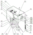
图4是本发明一种茎秆粉碎还田玉米收割机的升降台的立体结构示意图;Fig. 4 is a three-dimensional structural schematic diagram of a lifting platform of a corn harvester for stalk crushing and returning to fields of the present invention;
图5是本发明一种茎秆粉碎还田玉米收割机的升降台的收割台箱体的后视图;5 is a rear view of the header box of the lifting table of a corn harvester for stalk crushing and returning to the field of the present invention;
图6是本发明一种茎秆粉碎还田玉米收割机的升降台的进料板主体的立体结构示意图。6 is a schematic three-dimensional structural diagram of the main body of the feeding plate of the lifting platform of a corn harvester for crushing and returning stalks to the field according to the present invention.
图中:1-收割台箱体、101-第一轴承座、102-第一轴承盖、103-第二轴承座、104-第二轴承盖、105-第三轴承座、106-第三轴承盖、107-第四轴承座、108-第四轴承盖、109-第五轴承座、110-L形凸台、2-轮系结构、21-第一轴、22-第一圆锥齿轮、23-第二圆锥齿轮、24-第二轴、25-第三圆锥齿轮、26-第三轴、27-第四圆锥齿轮、3-进料板主体、31-槽孔、32-圆孔、33-滑轨固定座、34-凸台、4-螺旋进料机构、41-圆锥体、42-进料刀片、43-圆台、44-滚轮刀片、5-收割刀机构、51-轴套、52-刀背、53-刀刃、54-第四轴、55-第五圆锥齿轮、6-拨料机构、61-滑轨轴、62-弹簧、63-滑块、64-从动链轮、65-第五轴、66-主动链轮、67-链条、68-拔杆。In the figure: 1-header box, 101-first bearing seat, 102-first bearing cover, 103-second bearing seat, 104-second bearing cover, 105-third bearing seat, 106-third bearing Cover, 107-fourth bearing seat, 108-fourth bearing cover, 109-fifth bearing seat, 110-L-shaped boss, 2-gear train structure, 21-first shaft, 22-first bevel gear, 23 -Second bevel gear, 24-Second shaft, 25-Third bevel gear, 26-Third shaft, 27-Fourth bevel gear, 3-Feed plate body, 31-Slot hole, 32-Round hole, 33 -Slide rail fixed seat, 34-boss, 4-screw feeding mechanism, 41-cone, 42-feeding blade, 43-round table, 44-roller blade, 5-harvester mechanism, 51-sleeve, 52 -Knife back, 53-Blade, 54-Fourth shaft, 55-Fifth bevel gear, 6-Dialing mechanism, 61-Slide rail shaft, 62-Spring, 63-Slider, 64-Driver sprocket, 65- Fifth shaft, 66-drive sprocket, 67-chain, 68-pull rod.
【具体实施方式】【Detailed ways】
参阅图1、图2、图3、图4、图5和图6,本发明,包括包括收割台箱体1、轮系结构2、进料板主体3、螺旋进料机构4、收割刀机构5和拨料机构6,所述收割台体1内部设有轮系结构2,轮系结构2上端机械配合有收割刀机构5,收割刀机构5设于收割台箱体1正正上端;所述收割台箱体1后端固定有进料板主体3,进料板主体3的正上方设有螺旋进料机构4,螺旋进料机构4设于收割台箱体1后端,螺旋进料机构4与轮系结构2机械配合;所述收割台箱体1底部机械配合有拨料机构6。Referring to Figure 1, Figure 2, Figure 3, Figure 4, Figure 5 and Figure 6, the present invention includes a
具体的,所述收割台箱体1为前端带开口的空心壳体结构;所述收割台箱体1左端端面固设有第一轴承座101,第一轴承座101左端设有第一轴承盖102;所述收割台箱体1后端端面固设有第二轴承座103,第二轴承座103后端设有第二轴承盖104;所述收割台箱体1右端端面固设有第三轴承座105,第三轴承座105右端设有第三轴承盖106;所述收割台箱体1下端端面左右均固设有第四轴承座107,第四轴承座107下端设有第四轴承盖108;所述收割台箱体1下端左右对称设有L形凸台110;所述轮系结构2包括第一轴21、第一圆锥齿轮22、第二圆锥齿轮23、第二轴24、第三圆锥齿轮25、第三轴26和第四圆锥齿轮27;所述第一轴承座101和第三轴承座105内置设有第一轴21,第一轴21横向设置于第一轴承座101和第三轴承座105内的轴承内,第一轴21右端套装有圆锥齿轮22,第一轴21左端套装有圆台齿轮23;所述第四轴承座107内置设有第二轴24,所述第二轴24上端套装有第三圆锥齿轮25;所述第五轴承座109内置设有第三轴26,所述第三轴26前端套装有第四圆锥齿轮27,第四圆锥齿轮27与圆锥齿轮22或圆台齿轮23相啮合,圆锥齿轮22、圆台齿轮23均啮合有第三圆锥齿轮25。Specifically, the
具体的,所述进料板主体3下底板左右纵向开有槽孔31,槽孔31四周的进料板主体3上设有圆孔32;所述进料板主体3底面横向设有凸台34,凸台34为方形薄壁结构,凸台34中部设有圆形通孔;所述进料板主体3后端左右对称设有的滑轨固定座33,滑轨固定座33通过螺栓组件固定于圆孔32处;所述进料板主体3内侧与收割台箱体1的L型凸台110外侧贴合固定,进料板主体3前端与收割台箱体1后端贴合固定;所述槽孔31为键槽型结构;所述滑轨固定座33为L形,滑轨固定座33的上端面设有圆孔,滑轨固定座33内腔内设有肋板,滑轨固定座33侧面为梯形。Specifically, the lower bottom plate of the feeding plate
具体的,所述螺旋进料机构4包括圆锥体41、进料刀片42、圆台43和滚轮刀片44,圆台43外部沿圆周设有滚轮刀片44,滚轮刀片44的数量为8,滚轮刀片44与圆台43外端面垂直安装;所述圆台43后端的端面上固设有圆锥体41,圆锥体41底面直径大于圆台43后端面直径,圆锥体41外部沿圆周设有进料刀片42,进料刀片42为螺旋刀片,进料刀片42与圆锥体41外端面垂直安装;所述圆台43中部设有轴孔,圆台43中部通过轴连接轮系结构2。Specifically, the
具体的,所述收割刀机构5包括收割刀、第四轴54和第五圆锥齿轮55,收割刀中部过盈配合有第四轴54,第四轴54为阶梯轴,第四轴54下方通过螺钉固定有第五圆锥齿轮55,第五圆锥齿轮55与轮系结构2相啮合;所述收割刀包括轴套51和刀体,轴套51为圆环形结构,轴套51外圆周上固设有数量为3的刀体,刀体包括刀背52和刀刃53。Specifically, the
具体的,所述进料板主体3上的滑轨固定座33内置有滑轨轴61,所述滑轨轴61外套装有弹簧62,所述滑轨轴61下端固定有滑块63,所述滑块63内置有第五轴65,所述第五轴65上通过键连接有从动链轮64;所述轮系结构2的第二轴24下端通过键连接有主动链轮66,主动链轮66外啮合有链条67,链条67内圈与从动链轮64的外链齿相啮合,所述链条67上等距固定有拨杆68。Specifically, the slide
本发明工作过程:The working process of the present invention:
本发明一种茎秆粉碎还田玉米收割机的升降台在工作过程中,结合附图进行说明。The lifting platform of a corn harvester for stalk crushing and returning to the field of the present invention is described in conjunction with the accompanying drawings during the working process.
轮系结构2外接电机轴,从而使得本装置具有动力。本装置安装于玉米收割机上。轮系结构2运动,从而能带动拨料机构6运动,将玉米秸杆往螺旋进料机构4中间拨动;螺旋进料机构4对秸秆进行送料;收割刀机构5在轮系结构2的动力传递下,利用收割刀的刀刃53对秸秆进行切割,从而完成了收割还田的动作;结合传输结构等其他结构,实现玉米收割。滑轨固定座33、滑轨轴61、弹簧62和滑块63的组合使用,实现了拨料机构6的链传动间距的自动弹性调整,避免卡死。The
本发明,能够利用拨料机构拨动玉米秸秆至中间的螺旋进料机构进行进料,利用收割刀机构的收割刀对秸秆进行切割。本发明结构用于收割机小车,作为茎秆粉碎的主体装置。In the present invention, the corn stalk can be moved by the feeding mechanism to the middle screw feeding mechanism for feeding, and the reaping knife of the reaping knife mechanism can be used to cut the stalk. The structure of the present invention is used for a harvester trolley as the main device for stalk crushing.
上述实施例是对本发明的说明,不是对本发明的限定,任何对本发明简单变换后的方案均属于本发明的保护范围。The above-mentioned embodiments are illustrative of the present invention, not limitations of the present invention, and any scheme after simple transformation of the present invention belongs to the protection scope of the present invention.
Claims (6)
Priority Applications (1)
| Application Number | Priority Date | Filing Date | Title |
|---|---|---|---|
| CN201910991731.XA CN110679286A (en) | 2019-10-18 | 2019-10-18 | A lifting platform of a corn harvester with stalk crushing and returning to the field |
Applications Claiming Priority (1)
| Application Number | Priority Date | Filing Date | Title |
|---|---|---|---|
| CN201910991731.XA CN110679286A (en) | 2019-10-18 | 2019-10-18 | A lifting platform of a corn harvester with stalk crushing and returning to the field |
Publications (1)
| Publication Number | Publication Date |
|---|---|
| CN110679286A true CN110679286A (en) | 2020-01-14 |
Family
ID=69113487
Family Applications (1)
| Application Number | Title | Priority Date | Filing Date |
|---|---|---|---|
| CN201910991731.XA Pending CN110679286A (en) | 2019-10-18 | 2019-10-18 | A lifting platform of a corn harvester with stalk crushing and returning to the field |
Country Status (1)
| Country | Link |
|---|---|
| CN (1) | CN110679286A (en) |
Cited By (2)
| Publication number | Priority date | Publication date | Assignee | Title |
|---|---|---|---|---|
| CN115152411A (en) * | 2022-08-18 | 2022-10-11 | 吉林农信机械制造有限公司 | Straw crushing and returning device for harvester |
| CN119073081A (en) * | 2024-11-08 | 2024-12-06 | 贵州莽恳生态农业发展有限公司 | A self-propelled harvesting device for silage corn |
Citations (7)
| Publication number | Priority date | Publication date | Assignee | Title |
|---|---|---|---|---|
| CN2461259Y (en) * | 2001-01-12 | 2001-11-28 | 李金凡 | Small maize combine |
| CN201032769Y (en) * | 2007-08-15 | 2008-03-12 | 李全贞 | Corn combine and corn harvesting machine thereof |
| CN201499460U (en) * | 2009-10-19 | 2010-06-09 | 天津毕晟智能科技开发有限公司 | Reel type corn snapping and straw grinding device |
| CN103340058A (en) * | 2013-06-19 | 2013-10-09 | 山东理工大学 | Cutter embedding type stalk pulling, ear picking and straw cutting unit body |
| CN208242249U (en) * | 2018-05-04 | 2018-12-18 | 抚顺鑫兴农业机械有限责任公司 | A kind of corn harvester header |
| CN208353959U (en) * | 2018-07-12 | 2019-01-11 | 石家庄天人农业机械装备有限公司 | Straw chopping type gear box special for corn header |
| CN211430095U (en) * | 2019-10-18 | 2020-09-08 | 杭州乾达航空科技有限公司 | Lifting platform of corn harvester for smashing stalks and returning stalks to field |
-
2019
- 2019-10-18 CN CN201910991731.XA patent/CN110679286A/en active Pending
Patent Citations (7)
| Publication number | Priority date | Publication date | Assignee | Title |
|---|---|---|---|---|
| CN2461259Y (en) * | 2001-01-12 | 2001-11-28 | 李金凡 | Small maize combine |
| CN201032769Y (en) * | 2007-08-15 | 2008-03-12 | 李全贞 | Corn combine and corn harvesting machine thereof |
| CN201499460U (en) * | 2009-10-19 | 2010-06-09 | 天津毕晟智能科技开发有限公司 | Reel type corn snapping and straw grinding device |
| CN103340058A (en) * | 2013-06-19 | 2013-10-09 | 山东理工大学 | Cutter embedding type stalk pulling, ear picking and straw cutting unit body |
| CN208242249U (en) * | 2018-05-04 | 2018-12-18 | 抚顺鑫兴农业机械有限责任公司 | A kind of corn harvester header |
| CN208353959U (en) * | 2018-07-12 | 2019-01-11 | 石家庄天人农业机械装备有限公司 | Straw chopping type gear box special for corn header |
| CN211430095U (en) * | 2019-10-18 | 2020-09-08 | 杭州乾达航空科技有限公司 | Lifting platform of corn harvester for smashing stalks and returning stalks to field |
Cited By (3)
| Publication number | Priority date | Publication date | Assignee | Title |
|---|---|---|---|---|
| CN115152411A (en) * | 2022-08-18 | 2022-10-11 | 吉林农信机械制造有限公司 | Straw crushing and returning device for harvester |
| CN119073081A (en) * | 2024-11-08 | 2024-12-06 | 贵州莽恳生态农业发展有限公司 | A self-propelled harvesting device for silage corn |
| CN119073081B (en) * | 2024-11-08 | 2025-03-25 | 贵州莽恳生态农业发展有限公司 | A self-propelled harvesting device for silage corn |
Similar Documents
| Publication | Publication Date | Title |
|---|---|---|
| CN103340058A (en) | Cutter embedding type stalk pulling, ear picking and straw cutting unit body | |
| CN103238417B (en) | Fringe and stalk harvesting type corn reaping machine gearbox | |
| CN106031341A (en) | Hay cutting crusher | |
| CN109005928A (en) | Corn stover field, which is picked up, crushes uniformly distributed returning to the field special machine | |
| CN211430095U (en) | Lifting platform of corn harvester for smashing stalks and returning stalks to field | |
| CN204014531U (en) | Seed production corn male parent straw cutting apparatus | |
| CN106171280A (en) | A kind of self-propelled corn straw harvesting machine | |
| CN209359029U (en) | A kind of high bar crop cropper convenient for rewinding | |
| CN109511362B (en) | Mud flat mower | |
| CN208924659U (en) | A kind of double acting knife reciprocating-type cutting device | |
| CN218125553U (en) | A straw crushing and returning device for a harvester | |
| CN206978048U (en) | It is a kind of to cut smooth gardens hay mover | |
| CN213718612U (en) | Smash integral type triaxial straw still field machine | |
| CN104541612A (en) | Deep scarification soil-fetching mechanism for deep scarification and smashing multi-purpose machine | |
| CN103518430A (en) | Portable packing auger type grape vine burying machine with rotary cutters | |
| CN108738646B (en) | Weeder that facilitates use | |
| CN209030609U (en) | Ear harvesting device of corn harvester | |
| CN202514253U (en) | Stubble-cleaning rotary tillage machine | |
| CN107683712A (en) | The structure of the head of the double-blade brush cutter | |
| CN210770142U (en) | Reverse transmission case of combined soil preparation machine | |
| CN204985585U (en) | Rural area tiller transmission system | |
| CN221728959U (en) | A kind of integrated equipment for external baling of harvester | |
| CN222954354U (en) | A new agricultural tillage machine | |
| CN210130076U (en) | Self-walking agricultural machine | |
| CN204907207U (en) | Cut grass and plough all -in -one scissors transmission case a little |
Legal Events
| Date | Code | Title | Description |
|---|---|---|---|
| PB01 | Publication | ||
| PB01 | Publication | ||
| SE01 | Entry into force of request for substantive examination | ||
| SE01 | Entry into force of request for substantive examination | ||
| AD01 | Patent right deemed abandoned | ||
| AD01 | Patent right deemed abandoned |
Effective date of abandoning: 20250415 |