CN110670770A - Combined structure and construction method of solid shear wall and laminated plate edge member - Google Patents
Combined structure and construction method of solid shear wall and laminated plate edge member Download PDFInfo
- Publication number
- CN110670770A CN110670770A CN201910895100.8A CN201910895100A CN110670770A CN 110670770 A CN110670770 A CN 110670770A CN 201910895100 A CN201910895100 A CN 201910895100A CN 110670770 A CN110670770 A CN 110670770A
- Authority
- CN
- China
- Prior art keywords
- edge member
- steel bars
- plate type
- concrete
- shear wall
- Prior art date
- Legal status (The legal status is an assumption and is not a legal conclusion. Google has not performed a legal analysis and makes no representation as to the accuracy of the status listed.)
- Withdrawn
Links
- 239000007787 solid Substances 0.000 title claims abstract description 54
- 238000010276 construction Methods 0.000 title abstract description 17
- 229910000831 Steel Inorganic materials 0.000 claims abstract description 69
- 239000010959 steel Substances 0.000 claims abstract description 69
- 239000004567 concrete Substances 0.000 claims abstract description 61
- 238000000034 method Methods 0.000 claims abstract description 14
- 238000004519 manufacturing process Methods 0.000 claims abstract description 9
- 230000002787 reinforcement Effects 0.000 claims description 37
- 239000010410 layer Substances 0.000 claims description 33
- 238000009434 installation Methods 0.000 claims description 15
- 229910001294 Reinforcing steel Inorganic materials 0.000 claims description 14
- 239000002002 slurry Substances 0.000 claims description 13
- 239000002131 composite material Substances 0.000 claims description 9
- XLYOFNOQVPJJNP-UHFFFAOYSA-N water Substances O XLYOFNOQVPJJNP-UHFFFAOYSA-N 0.000 claims description 8
- 239000011178 precast concrete Substances 0.000 claims description 7
- 239000003795 chemical substances by application Substances 0.000 claims description 6
- 239000011241 protective layer Substances 0.000 claims description 3
- 238000003466 welding Methods 0.000 claims description 3
- 239000011248 coating agent Substances 0.000 claims 2
- 238000000576 coating method Methods 0.000 claims 2
- 230000005611 electricity Effects 0.000 claims 2
- 238000004140 cleaning Methods 0.000 claims 1
- 238000003825 pressing Methods 0.000 claims 1
- 230000000452 restraining effect Effects 0.000 claims 1
- 238000007788 roughening Methods 0.000 claims 1
- 238000010025 steaming Methods 0.000 claims 1
- 239000011150 reinforced concrete Substances 0.000 abstract description 7
- 230000007613 environmental effect Effects 0.000 abstract description 4
- 239000000203 mixture Substances 0.000 abstract 1
- 238000010586 diagram Methods 0.000 description 25
- 238000009415 formwork Methods 0.000 description 15
- 230000003014 reinforcing effect Effects 0.000 description 6
- 239000011120 plywood Substances 0.000 description 4
- 238000004873 anchoring Methods 0.000 description 3
- 238000001125 extrusion Methods 0.000 description 2
- 238000011065 in-situ storage Methods 0.000 description 2
- 239000000463 material Substances 0.000 description 2
- 230000009286 beneficial effect Effects 0.000 description 1
- 238000009435 building construction Methods 0.000 description 1
- 230000001934 delay Effects 0.000 description 1
- 238000003860 storage Methods 0.000 description 1
- 230000004083 survival effect Effects 0.000 description 1
Images















Classifications
-
- E—FIXED CONSTRUCTIONS
- E04—BUILDING
- E04B—GENERAL BUILDING CONSTRUCTIONS; WALLS, e.g. PARTITIONS; ROOFS; FLOORS; CEILINGS; INSULATION OR OTHER PROTECTION OF BUILDINGS
- E04B2/00—Walls, e.g. partitions, for buildings; Wall construction with regard to insulation; Connections specially adapted to walls
- E04B2/84—Walls made by casting, pouring, or tamping in situ
- E04B2/86—Walls made by casting, pouring, or tamping in situ made in permanent forms
-
- E—FIXED CONSTRUCTIONS
- E04—BUILDING
- E04G—SCAFFOLDING; FORMS; SHUTTERING; BUILDING IMPLEMENTS OR AIDS, OR THEIR USE; HANDLING BUILDING MATERIALS ON THE SITE; REPAIRING, BREAKING-UP OR OTHER WORK ON EXISTING BUILDINGS
- E04G21/00—Preparing, conveying, or working-up building materials or building elements in situ; Other devices or measures for constructional work
Landscapes
- Engineering & Computer Science (AREA)
- Architecture (AREA)
- Civil Engineering (AREA)
- Structural Engineering (AREA)
- Physics & Mathematics (AREA)
- Electromagnetism (AREA)
- Mechanical Engineering (AREA)
- Reinforcement Elements For Buildings (AREA)
Abstract
实心剪力墙与叠合板式边缘构件组合结构及施工方法。现阶段钢筋混凝土剪力墙结构边缘构件纵向钢筋套筒连接成本高,灌浆工序对环境要求较高、施工难度大且连接质量不易保证。本发明组成包括:该叠合板式边缘构件为一个或多个一字型边缘构件(1)组成,所述的一字型边缘构件是由两层预制混凝土薄板(2)和预埋在两层所述的预制混凝土薄板内的纵向钢筋(3)和箍筋(4)组成,两层所述的预制叠合板式混凝土间设置桁架钢筋(5)、拉结筋(6)。本发明用于实心剪力墙与叠合板式边缘构件组合结构的生产。
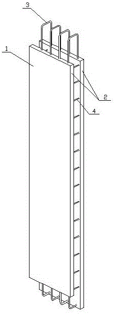
Combined structure and construction method of solid shear wall and laminated plate edge member. At this stage, the connection cost of longitudinal steel sleeves for edge members of reinforced concrete shear wall structures is high, the grouting process requires high environmental requirements, and the construction is difficult and the connection quality is not easy to guarantee. The composition of the invention includes: the laminated plate edge member is composed of one or more in-line edge members (1), and the in-line edge member is composed of two layers of prefabricated concrete sheets (2) and pre-buried in two layers. The longitudinal steel bars (3) and the stirrups (4) in the prefabricated concrete sheet are composed, and truss steel bars (5) and tie bars (6) are arranged between the two layers of the prefabricated laminated concrete. The invention is used for the production of the combined structure of the solid shear wall and the laminated plate type edge member.
Description
技术领域:Technical field:
本发明涉及一种实心剪力墙与叠合板式边缘构件组合结构及施工方法。The invention relates to a combined structure and a construction method of a solid shear wall and a laminated plate edge member.
背景技术:Background technique:
装配式建筑较传统的现浇结构有着明显的技术优势,节省人工、节省模板、节省机械,提高成活质量,减少排放、减少污染,节约工期,节省成本,但对于不同的装配式建筑施工方式,所产生的经济效益和社会效益是不同的。现阶段钢筋混凝土剪力墙结构边缘构件纵向钢筋多数通过套筒连接且每根都需要连接,套筒成本、预制构件制作及安装人工成本、灌浆料成本、灌浆人工成本都比较高,灌浆工序对环境要求较高、施工难度大且连接质量不易保证,灌浆饱满度检测难度较大,对工程质量造成安全隐患。Prefabricated buildings have obvious technical advantages over traditional cast-in-place structures, saving labor, formwork, machinery, improving survival quality, reducing emissions, reducing pollution, saving construction periods, and saving costs, but for different prefabricated building construction methods, The resulting economic and social benefits are different. At present, most of the longitudinal reinforcing bars of the edge members of reinforced concrete shear wall structures are connected by sleeves, and each needs to be connected. The cost of sleeves, the labor cost of prefabricated components, the cost of grouting material, and the cost of grouting labor are relatively high. The environmental requirements are high, the construction is difficult, and the connection quality is not easy to guarantee.
发明内容:Invention content:
本发明的目的是解决现阶段钢筋混凝土剪力墙结构边缘构件纵向钢筋连接成本高,灌浆工序对环境要求较高、施工难度大且连接质量不易保证的问题,提供一种降低制作成本、保证质量的实心剪力墙与叠合板式边缘构件组合结构及施工方法。The purpose of the present invention is to solve the problems of high connection cost of longitudinal steel bars of edge members of reinforced concrete shear wall structure at the present stage, high environmental requirements for grouting process, high construction difficulty and difficulty in ensuring connection quality, and to provide a method that reduces production cost and guarantees quality. The combined structure and construction method of solid shear wall and laminated plate edge member.
上述的目的通过以下的技术方案实现:The above purpose is achieved through the following technical solutions:
一种叠合板式边缘构件,该叠合板式边缘构件为一个或多个一字型边缘构件组成,所述的一字型边缘构件是由两层预制混凝土薄板和预埋在两层所述的预制混凝土薄板内的纵向钢筋和箍筋组成,两层所述的预制叠合板式混凝土间设置拉结筋。A laminated plate type edge member, the laminated plate type edge member is composed of one or more in-line edge members, and the in-line type edge member is composed of two layers of prefabricated concrete sheets and pre-buried in the two layers. It is composed of longitudinal steel bars and stirrups in the prefabricated concrete sheet, and tie bars are arranged between the two layers of the prefabricated laminated slab concrete.
所述的叠合板式边缘构件,所述的纵向钢筋为封闭环状,上下两层所述的纵向钢筋相互交接重叠并形成交接空隙,在形成的交接空隙中插入销接纵筋形成销接结构。In the laminated plate edge member, the longitudinal reinforcing bars are closed rings, the longitudinal reinforcing bars of the upper and lower layers are mutually overlapped and overlapped with each other to form a handover gap, and a pinned longitudinal bar is inserted into the formed handover gap to form a pinned structure. .
所述的叠合板式边缘构件,所述的纵向钢筋为直钢筋,上下两层所述的纵向钢筋通过套筒或焊接或搭接或约束搭接连接。In the laminated plate edge member, the longitudinal steel bars are straight steel bars, and the upper and lower layers of the longitudinal steel bars are connected by sleeves or welding or lap joints or restrained lap joints.
所述的叠合板式边缘构件,所述的预制叠合板式边缘构件为一字型或L型或T型或+型或Z型或U型。For the laminated plate edge member, the prefabricated laminated plate edge member is in-line or L-shaped or T-shaped or +-shaped or Z-shaped or U-shaped.
所述的叠合板式边缘构件,两层所述的预制混凝土薄板间预埋桁架钢筋,所述的箍筋为封闭环状。In the superimposed plate edge member, the truss steel bars are pre-embedded between the two layers of the precast concrete thin plates, and the stirrups are closed rings.
一种实心剪力墙与叠合板式边缘构件组合结构,所述的叠合板式边缘构件端部连接实心剪力墙,所述的实心剪力墙外伸水平钢筋,所述的外伸水平钢筋伸入所述的叠合板式边缘构件的空腔内并固定。A combined structure of a solid shear wall and a laminated plate edge member, wherein the end of the laminated plate edge member is connected to a solid shear wall, the solid shear wall extends horizontal steel bars, and the external horizontal steel bars extend Extend into the cavity of the laminated panel edge member and fix it.
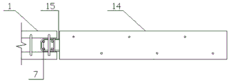
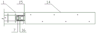
所述的实心剪力墙与叠合板式边缘构件组合结构,所述的实心剪力墙外伸水平钢筋为环状钢筋,所述的外伸水平钢筋伸入所述的叠合板式边缘构件的空腔并与所述的叠合板式边缘构件的封闭环状箍筋交接形成交接空隙,并在交接空隙中插入销接纵筋形成销接结构。In the combined structure of the solid shear wall and the superimposed plate edge member, the outstretched horizontal reinforcement of the solid shear wall is a ring-shaped reinforcement, and the outstretched horizontal reinforcement extends into the edge of the superimposed plate edge member. The cavity is connected with the closed annular stirrups of the laminated plate-type edge member to form a handover space, and a pinned longitudinal rib is inserted into the handover space to form a pinned structure.
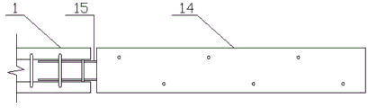
所述的叠合板式边缘构件与实心剪力墙组合结构,所述的实心剪力墙外伸水平钢筋为直钢筋或对扣L型钢筋,所述的外伸水平钢筋伸入所述的叠合板式边缘构件的空腔内,并锚入叠合板式边缘构件空腔内现浇混凝土中。In the composite structure of the superimposed plate edge member and the solid shear wall, the outstretched horizontal steel bar of the solid shear wall is a straight bar or a pair of L-shaped bars, and the outstretched horizontal bar extends into the stack. into the cavity of the plywood edge member, and anchored into the cast-in-place concrete in the cavity of the plywood edge member.
一种叠合板式边缘构件的施工方法,A construction method of a laminated panel edge member,
该方法包括如下步骤:The method includes the following steps:
(1)先支设一侧混凝土薄板模板,在模板内涂刷脱模剂,放置预先绑扎好的边缘构件钢筋笼;(1) First set up a concrete sheet formwork on one side, apply a release agent in the formwork, and place a pre-bound edge member reinforcement cage;
(2)将钢筋笼放入支设好的模板内,放置一定数量的钢筋保护层垫块,预埋固定水电线盒、临时支撑件及其他埋件;(2) Put the steel cage into the supported formwork, place a certain number of steel protective layer pads, and pre-embed and fix the water and wire boxes, temporary supports and other embedded parts;
(3)浇筑现浇混凝土至模板上表面,振捣混凝土,静停混凝土并拉毛,对浇筑完成后的混凝土进行养护达到吊装强度后,将带有钢筋笼的混凝土薄板翻转备用;(3) Pour the cast-in-place concrete to the upper surface of the formwork, vibrate the concrete, stop the concrete statically and roughen it, and maintain the poured concrete to reach the hoisting strength, and then turn the concrete sheet with the reinforcement cage for use;
(4)支设另一侧混凝土薄板模板,设置叠合式边缘构件厚度控制装置,涂刷脱模剂,预埋固定水电线盒、临时支撑件及其他埋件;(4) Set up the other side of the concrete sheet formwork, set up the thickness control device of the superimposed edge member, apply the release agent, and pre-embed and fix the water and wire boxes, temporary supports and other embedded parts;
(5)浇筑混凝土并振捣,将带有混凝土薄板的钢筋笼另一侧压入浇筑完混凝土的模板内,保证叠合板式边缘构件总体厚度和两层混凝土薄板相对位置关系;(5) Concrete is poured and vibrated, and the other side of the reinforcement cage with the concrete sheet is pressed into the formwork of the poured concrete to ensure the overall thickness of the laminated edge member and the relative positional relationship between the two layers of concrete sheets;
(6)对混凝土内表面进行拉毛处理并蒸养,完成预制叠合板式边缘构件的生产。(6) The inner surface of the concrete is roughened and steam cured to complete the production of prefabricated laminated panel edge members.
(7)对需要组合的一字型边缘构件设置连接件,在叠合板式边缘构件安装前根据边缘构件形式,对边缘构件进行临时固定,形成一字型、L型、T型、+型、Z型、U型边缘构件。(7) Provide connectors for the in-line edge members that need to be combined, and temporarily fix the edge members according to the form of the edge members before the laminated plate edge members are installed to form in-line, L-shaped, T-shaped, +-shaped, Z-shaped, U-shaped edge members.
一种实心剪力墙与叠合板式边缘构件组合结构的施工方法,该方法包括如下步骤:A construction method for a combined structure of a solid shear wall and a laminated plate edge member, the method comprising the following steps:
(1)安装预制实心剪力墙,对安装作业面进行剔凿、清扫并浇水湿润,调整钢筋垂直度,放置垫块并抄测垫块标高,铺设座浆料,座浆料沿墙长方向中间略高于垫块并保证垫块上无浆料,座浆料的量以填满墙体底部整个坐浆层为宜,及时吊装墙体,使墙体底部连接孔对准作业面预埋的剪力墙钢筋;(1) Install the prefabricated solid shear wall, chisel, clean and water the installation surface, adjust the verticality of the steel bars, place the pads and measure the elevation of the pads, and lay the seat slurry along the length of the wall. The middle of the direction is slightly higher than the cushion block and ensure that there is no slurry on the cushion block. The amount of the seat slurry is appropriate to fill the entire slurry layer at the bottom of the wall. Lift the wall in time, so that the connecting hole at the bottom of the wall is aligned with the working surface. Buried shear wall reinforcement;
(2)安装斜支撑,按照墙体控制线及预制构件轮廓线调整安装位置,调整墙体垂直度,固定斜支撑;(2) Install the inclined support, adjust the installation position according to the wall control line and the outline of the prefabricated component, adjust the verticality of the wall, and fix the inclined support;
(3)根据边缘构件形式,对预制叠合板式边缘构件进行拼装,拼装成L型、T型、+型、Z型、U型,吊装叠合板式边缘构件,叠合板式边缘构件垂直下落后,水平移动叠合板式边缘构件,使实心剪力墙外伸钢筋进入叠合板式边缘构件内,实心剪力墙外伸钢筋同叠合板式边缘构件环状箍筋形成交接空隙,空隙中插入销接纵筋,形成销接结构;(3) According to the form of the edge member, assemble the prefabricated laminated edge members into L-shaped, T-shaped, +-shaped, Z-shaped, U-shaped, hoist the laminated-shaped edge member, and after the laminated-shaped edge member falls vertically , Move the superimposed plate edge member horizontally, so that the solid shear wall outstretched steel bars enter the superimposed plate edge member, and the solid shear wall outstretched steel bars and the superimposed plate edge member annular stirrups form an intersection gap, and a pin is inserted into the gap. Connect longitudinal ribs to form a pinned structure;
(4)按照墙体控制线及预制构件轮廓线调整安装位置,调整墙体垂直度,固定斜支撑,在实心剪力墙外伸钢筋同叠合板式边缘构件环状箍筋形成交接空隙中插入销接钢筋,在叠合板式边缘构件底部环状钢筋形成的交接空隙中插入销接钢筋,安装叠合梁、叠合板等其他构件;(4) Adjust the installation position according to the wall control line and the contour line of the prefabricated components, adjust the verticality of the wall, fix the diagonal support, and insert into the intersection gap formed by the solid shear wall outrigger reinforcement and the annular stirrup of the superimposed plate edge member. For pin-connected steel bars, insert pin-connected steel bars in the intersection space formed by the ring-shaped steel bars at the bottom of the laminated plate edge member, and install other components such as laminated beams and laminated plates;
(5)支设实心剪力墙与叠合板式边缘构件中间安装缝隙、叠合板式边缘构件底部缝隙及开洞位置模板,在叠合板式边缘构件中部空腔内浇筑混凝土并振捣,完成叠合板式边缘构件组合结构的安装。(5) Support the installation gap between the solid shear wall and the laminated edge member, the gap at the bottom of the laminated edge member and the template for the opening position, and pour concrete in the middle cavity of the laminated edge member and vibrate to complete the stacking. Installation of plywood edge member composite structures.
有益效果:Beneficial effects:
1.本发明解决钢筋混凝土剪力墙结构边缘构件制作成本、安装成本高的弊端。现阶段钢筋混凝土剪力墙结构边缘构件纵向钢筋多数通过套筒连接且每根都需要连接,套筒成本、预制构件制作、安装人工成本、灌浆料成本、灌浆人工成本都比较高,灌浆工序对环境要求较高且连接质量不易保证,灌浆饱满度检测难度较大对工程质量造成安全隐患。1. The present invention solves the disadvantages of high manufacturing cost and high installation cost of edge members of reinforced concrete shear wall structure. At this stage, most of the longitudinal reinforcing bars of the edge members of reinforced concrete shear wall structures are connected by sleeves, and each needs to be connected. The cost of sleeves, the production of prefabricated components, the labor cost of installation, the cost of grouting material, and the cost of grouting labor are relatively high. The environmental requirements are high and the connection quality is not easy to guarantee.
2. 本发明叠合板式边缘构件两侧为预制混凝土薄板,中间空腔现浇混凝土,结构整体性好,内部腔体较大混凝土浇筑密实度高。2. The two sides of the laminated plate edge member of the present invention are prefabricated concrete sheets, the middle cavity is cast-in-place concrete, the structural integrity is good, and the inner cavity is larger and the concrete pouring density is high.
3. 本发明叠合板式边缘构件两侧预制薄板充当模板无需再次支模,施工方便,减少木工作业量及作业难度,节省人工成本。3. The prefabricated sheets on both sides of the laminated plate edge member of the present invention do not need to support the formwork again, which is convenient for construction, reduces the workload and difficulty of woodwork, and saves labor costs.
4. 本发明预制构件质量轻,对现场吊装机械吊重要求较低,从机械选型上节省购买和租赁成本。4. The prefabricated components of the present invention are light in weight, have lower requirements on the hoisting weight of on-site hoisting machinery, and save purchase and rental costs from mechanical model selection.
5. 本发明解决装配式钢筋混凝土结构,L型、T型及其他形式暗柱通常现浇的弊端,降低现场支模、绑筋、浇筑混凝土的工作量,提高施工速度,缩短关键线路时间,缩短工期,降低财务成本。5. The present invention solves the disadvantages of prefabricated reinforced concrete structures, L-shaped, T-shaped and other forms of hidden columns that are usually cast-in-place, reduces the workload of on-site formwork, tie bars, and pouring concrete, improves construction speed, and shortens key line time. Shorten construction period and reduce financial cost.
6. 本发明减少现浇量,安装施工简单,减少施工现场工人用工数量,解决用工荒问题。6. The present invention reduces the amount of cast-in-place, simple installation and construction, reduces the number of workers employed on the construction site, and solves the problem of labor shortage.
7. 本发明预制叠合板式边缘构件为大幅度提高装配率提供途径,提高我国装配式钢筋混凝土装配技术水平。7. The prefabricated laminated plate edge member of the present invention provides a way to greatly improve the assembly rate and improve the technical level of prefabricated reinforced concrete in my country.
8. 本发明边缘构件同剪力墙分开制作,边缘构件尺寸标准化,构件通用性强可实现预制构件商品化,构件提前生产和储备生产,提高生产预制构件模板的利用率,现货供应有利于占领市场,提高市场份额。8. The edge member of the present invention is produced separately from the shear wall, the size of the edge member is standardized, the universality of the member is strong, the prefabricated member can be commercialized, the member is produced in advance and reserved for production, the utilization rate of the production prefabricated member template is improved, and the spot supply is conducive to occupation. market and increase market share.
9. 本发明边缘构件标准化便于存储及运输,避免现阶段由于构件厂堆场较大,预制构件摆放不合理造成寻找构件困难的现象,避免耽误现场安装进度。9. The standardization of the edge components of the present invention is convenient for storage and transportation, avoiding the phenomenon of difficulty in finding components due to the large yard of the component factory and the unreasonable placement of prefabricated components at the current stage, and avoiding delays in on-site installation progress.
附图说明:Description of drawings:
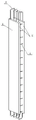
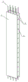
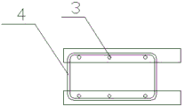
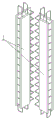
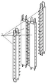
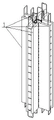
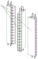
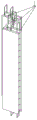
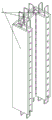
附图1是本发明的预制叠合板式边缘构件外伸纵向钢筋为环状示意图一;Accompanying drawing 1 is that the prefabricated laminated plate edge member of the present invention extends longitudinal reinforcing bar as a ring schematic diagram 1;
附图2是本发明的预制叠合板式边缘构件外伸纵向钢筋为环状示意图二;Accompanying drawing 2 is that the prefabricated laminated plate edge member of the present invention extends longitudinal reinforcement in a ring shape two;
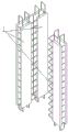
附图3是本发明的预制叠合板式边缘构件外伸纵向钢筋为直钢筋示意图;Accompanying drawing 3 is the schematic diagram that the prefabricated laminated plate edge member of the present invention extends longitudinal steel bar as straight steel bar;
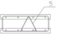
附图4是本发明的预制叠合板式边缘构件内部设置桁架钢筋剖面图;Accompanying drawing 4 is the sectional view of the truss steel bar set inside the prefabricated laminated plate edge member of the present invention;
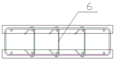
附图5是本发明的预制叠合板式边缘构件内部设置拉结钢筋剖面图;Accompanying drawing 5 is the sectional view of the prefabricated laminated plate edge member of the present invention set inside the tie reinforcement;
附图6是本发明的预制叠合板式边缘构件混凝土薄板端部加长示意图;6 is a schematic view of the lengthening of the end of the prefabricated laminated edge member concrete sheet of the present invention;
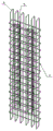
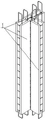
附图7是本发明的预制叠合板式边缘构件内部设置拉结钢筋钢筋笼示意图;Accompanying drawing 7 is the schematic diagram of the prefabricated laminated plate edge member of the present invention that is provided with a tie-bar reinforcing steel cage;
附图8是本发明的预制叠合板式边缘构件内部设置桁架钢筋钢筋笼示意图;8 is a schematic diagram of a truss steel reinforcement cage arranged inside the prefabricated laminated panel edge member of the present invention;
附图9是本发明的桁架钢筋示意图;9 is a schematic diagram of a truss steel bar of the present invention;
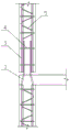
附图10是本发明的预制叠合板式边缘构件上下层间纵向钢筋销接结构连接节点示意图一;10 is a schematic diagram of the
附图11是本发明的预制叠合板式边缘构件上下层间纵向钢筋销接结构连接节点示意图二;Fig. 11 is a schematic diagram 2 of the connection node of the longitudinal reinforcement pin connection structure between the upper and lower layers of the prefabricated laminated plate edge member of the present invention;
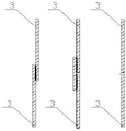
附图12是本发明的预制叠合板式边缘构件上下层间纵向钢筋为直钢筋连接节点示意图;12 is a schematic diagram of the connection node between the upper and lower layers of the prefabricated laminated panel edge member of the present invention being straight steel bars;
附图13是本发明的预制叠合板式边缘构件上下层间纵向钢筋为直钢筋搭接连接节点示意图;13 is a schematic diagram of the lap joint connection node of the prefabricated laminated plate edge member of the present invention between the upper and lower layers of the longitudinal steel bar is a straight steel bar;
附图14是本发明的预制叠合板式边缘构件上下层间纵向钢筋为直钢筋约束搭接连接节点示意图;14 is a schematic diagram of a prefabricated laminated panel edge member of the present invention, the longitudinal reinforcement between the upper and lower layers is a straight reinforcement constrained lap joint connection;
附图15是本发明的预制叠合板式边缘构件上下层间纵向钢筋为直钢筋焊接连接节点示意图;Figure 15 is a schematic diagram of the welded connection node of the prefabricated laminated plate edge member of the present invention between the upper and lower layers of the longitudinal steel bar is a straight steel bar;
附图16是本发明的预制叠合板式边缘构件上下层间纵向钢筋为直钢筋套筒连接节点示意图;16 is a schematic diagram of the connection node of the vertical steel bar between the upper and lower layers of the prefabricated laminated edge member of the present invention being a straight steel bar sleeve;
附图17是本发明的预制叠合板式边缘构件与实心剪力墙销接连接结构节点示意图一;Fig. 17 is a schematic diagram of the
附图18是本发明的预制叠合板式边缘构件与实心剪力墙销接连接结构节点示意图二;Figure 18 is the second schematic diagram of the pinned connection structure node between the prefabricated laminated plate edge member and the solid shear wall of the present invention;
附图19是本发明的预制叠合板式边缘构件与实心剪力墙销接连接结构附加钢筋环连接节点示意图一;Figure 19 is a schematic diagram of the
附图20是本发明的预制叠合板式边缘构件与实心剪力墙销接连接结构附加钢筋环连接节点示意图二;Fig. 20 is a schematic diagram 2 of the additional steel ring connection node of the prefabricated laminated plate edge member and the solid shear wall pinned connection structure of the present invention;
附图21是本发明实心剪力墙外伸直钢筋锚入叠合板式边缘构件空腔现浇混凝土示意图一;21 is a schematic diagram 1 of the cast-in-situ concrete of the solid shear wall of the present invention, anchoring the straight steel bar into the cavity of the laminated plate edge member;
附图22是本发明实心剪力墙外伸直钢筋锚入叠合板式边缘构件空腔现浇混凝土示意图二;Accompanying drawing 22 is the second schematic diagram of cast-in-situ concrete of the solid shear wall of the present invention, anchored into the cavity of the laminated plate edge member;
附图23是本发明实心剪力墙外伸对扣L型钢筋锚入叠合板式边缘构件空腔现浇混凝土示意图一;23 is a schematic diagram 1 of the cast-in-place concrete of the solid shear wall of the present invention, which is anchored into the cavity of the laminated plate edge member by anchoring the L-shaped steel bar with the buckle;
附图24是本发明实心剪力墙外伸对扣L型钢筋锚入叠合板式边缘构件空腔现浇混凝土示意图二;24 is a schematic diagram 2 of the cast-in-place concrete of the solid shear wall of the present invention, which is anchored into the cavity of the laminated plate-type edge member by anchoring the L-shaped steel bar with the buckle;
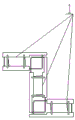
附图25是本发明的预制叠合板式L型边缘构件平面示意图;Figure 25 is a schematic plan view of the prefabricated laminated plate type L-shaped edge member of the present invention;
附图26是本发明的预制叠合板式L型边缘构件分解示意图;Figure 26 is a schematic exploded view of the prefabricated laminated L-shaped edge member of the present invention;
附图27是本发明的预制叠合板式L型边缘构件组合示意图;Figure 27 is a schematic diagram of the combination of prefabricated laminated plate L-shaped edge members of the present invention;
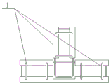
附图28是本发明的预制叠合板式T型边缘构件平面示意图;Figure 28 is a schematic plan view of the prefabricated laminated T-shaped edge member of the present invention;
附图29是本发明的预制叠合板式T型边缘构件分解示意图;Figure 29 is a schematic exploded view of the prefabricated laminated T-shaped edge member of the present invention;
附图30是本发明的预制叠合板式T型边缘构件组合示意图;Figure 30 is a schematic diagram of the prefabricated laminated T-shaped edge member assembly of the present invention;
附图31是本发明的预制叠合板式十型边缘构件平面示意图;Figure 31 is a schematic plan view of the prefabricated laminated plate type ten-shaped edge member of the present invention;
附图32是本发明的预制叠合板式十型边缘构件分解示意图;Fig. 32 is the exploded schematic diagram of the prefabricated laminated plate type ten-shaped edge member of the present invention;
附图33是本发明的预制叠合板式十型边缘构件组合示意图;Figure 33 is a schematic view of the prefabricated laminated plate type ten-shaped edge member combination of the present invention;
附图34是本发明的预制叠合板式Z型边缘构件平面示意图;34 is a schematic plan view of a prefabricated laminated plate type Z-shaped edge member of the present invention;
附图35是本发明的预制叠合板式Z型边缘构件分解示意图;Figure 35 is an exploded schematic view of the prefabricated laminated plate type Z-shaped edge member of the present invention;
附图36是本发明的预制叠合板式Z型边缘构件组合示意图;Figure 36 is a schematic diagram of the combination of prefabricated laminated plate Z-shaped edge members of the present invention;
附图37是本发明的预制叠合板式U型边缘构件平面示意图;Figure 37 is a schematic plan view of the prefabricated laminated plate type U-shaped edge member of the present invention;
附图38是本发明的预制叠合板式U型边缘构件分解示意图;Figure 38 is a schematic exploded view of the prefabricated laminated U-shaped edge member of the present invention;
附图39是本发明的预制叠合板式U型边缘构件组合示意图;Figure 39 is a schematic diagram of the combination of the prefabricated laminated plate type U-shaped edge member of the present invention;
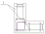
图中:1、边缘构件;2、预制混凝土薄板;3、纵向钢筋;4、箍筋;5、桁架钢筋;6、拉结筋;7、销接纵筋;8、螺旋箍筋;9、直螺纹套筒;10、锥螺纹套筒;11、挤压套筒;12、半灌浆套筒;13、全灌浆套筒;14、实心剪力墙;15、水平钢筋;16、钢筋环。In the figure: 1. Edge member; 2. Precast concrete sheet; 3. Longitudinal steel bar; 4. Stirrup; 5. Truss steel bar; 6. Tie bar; 7. Pinned longitudinal bar; Straight threaded sleeve; 10. Tapered threaded sleeve; 11. Extrusion sleeve; 12. Semi-grouted sleeve; 13. Full grouted sleeve; 14. Solid shear wall; 15. Horizontal steel bar; 16. Steel ring.
具体实施方式:Detailed ways:
实施例1:Example 1:
一种叠合板式边缘构件,该叠合板式边缘构件为一个或多个一字型边缘构件1组成,所述的一字型边缘构件是由两层预制混凝土薄板2和预埋在两层所述的预制混凝土薄板内的纵向钢筋3和箍筋4组成,两层所述的预制叠合板式混凝土间设置拉结筋6。A laminated plate type edge member, the laminated plate type edge member is composed of one or more in-
实施例2:Example 2:
根据实施例1所述的叠合板式边缘构件,所述的纵向钢筋为封闭环状,上下两层所述的纵向钢筋相互交接重叠并形成交接空隙,在形成的交接空隙中插入销接纵筋7形成销接结构。According to the laminated plate-type edge member according to
实施例3:Example 3:
根据实施例1或2所述的叠合板式边缘构件,所述的纵向钢筋为直钢筋,上下两层所述的纵向钢筋通过套筒或焊接或搭接或约束搭接连接。According to the laminated plate edge member according to
所的约束搭接连接是使用螺旋箍筋8部分预埋在预制混凝土薄板内并包裹纵向钢筋,外露部分用于插入下层预制叠合板式边缘构件纵向钢筋。所述的套筒连接方式有直螺纹套筒9连接、锥螺纹套筒10连接、挤压套筒11连接、半灌浆套筒12连接、全灌浆套筒13连接。The constrained lap connection is made by using
实施例4:Example 4:
根据实施例1或2或3所述的叠合板式边缘构件,所述的预制叠合板式边缘构件,所述的预制叠合板式边缘构件为一字型或L型或T型或+型或Z型或U型。According to the laminated board type edge member according to the
实施例5:Example 5:
根据实施例1或2或3或4所述的叠合板式边缘构件,两层所述的预制混凝土薄板间预埋桁架钢筋5,所述的箍筋为封闭环状结构。According to the laminated plate edge member described in
实施例6:Example 6:
一种实心剪力墙与叠合板式边缘构件组合结构,所述的叠合板式边缘构件端部连接实心剪力墙14,所述的实心剪力墙外伸水平钢筋15,所述的外伸水平钢筋伸入所述的叠合板式边缘构件的空腔内并固定。A combined structure of a solid shear wall and a laminated plate edge member, the end of the laminated plate edge member is connected to a
实施例7:Example 7:
根据实施例6所述的实心剪力墙与叠合板式边缘构件组合结构,所述的实心剪力墙外伸水平钢筋为环状钢筋,所述的外伸水平钢筋伸入所述的叠合板式边缘构件的空腔并与所述的叠合板式边缘构件的封闭环状箍筋交接形成交接空隙,并在交接空隙中插入销接纵筋形成销接结构或所述的实心剪力墙外伸水平钢筋15通过附加钢筋环16同边缘构件环状箍筋4分别交接形成交接空隙,所述的空隙中分别插入销接纵筋7,形成销接结构。According to the combined structure of the solid shear wall and the superimposed plate edge member according to
实施例8:Example 8:
根据实施例6所述的实心剪力墙与叠合板式边缘构件组合结构,所述的实心剪力墙外伸水平钢筋为直钢筋或对扣L型钢筋,所述的外伸水平钢筋伸入所述的叠合板式边缘构件的空腔内,并锚入叠合板式边缘构件空腔内现浇混凝土中。According to the combined structure of the solid shear wall and the superimposed plate edge member according to
实施例9:Example 9:
一种叠合板式边缘构件的施工方法,A construction method of a laminated panel edge member,
该方法包括如下步骤:The method includes the following steps:
(1)先支设一侧混凝土薄板模板,在模板内涂刷脱模剂,放置预先绑扎好的边缘构件钢筋笼;(1) First set up a concrete sheet formwork on one side, apply a release agent in the formwork, and place a pre-bound edge member reinforcement cage;
(2)将钢筋笼放入支设好的模板内,放置一定数量的钢筋保护层垫块,预埋固定水电线盒、临时支撑件及其他埋件;(2) Put the steel cage into the supported formwork, place a certain number of steel protective layer pads, and pre-embed and fix the water and wire boxes, temporary supports and other embedded parts;
(3)浇筑现浇混凝土至模板上表面,振捣混凝土,静停混凝土并拉毛,对浇筑完成后的混凝土进行养护达到吊装强度后,将带有钢筋笼的混凝土薄板翻转备用;(3) Pour the cast-in-place concrete to the upper surface of the formwork, vibrate the concrete, stop the concrete statically and roughen it, and maintain the poured concrete to reach the hoisting strength, and then turn the concrete sheet with the reinforcement cage for use;
(4)支设另一侧混凝土薄板模板,设置叠合式边缘构件厚度控制装置,涂刷脱模剂,预埋固定水电线盒、临时支撑件及其他埋件;(4) Set up the other side of the concrete sheet formwork, set up the thickness control device of the superimposed edge member, apply the release agent, and pre-embed and fix the water and wire boxes, temporary supports and other embedded parts;
(5)浇筑混凝土并振捣,将带有混凝土薄板的钢筋笼另一侧压入浇筑完混凝土的模板内,保证叠合板式边缘构件总体厚度和两层混凝土薄板相对位置关系;(5) Concrete is poured and vibrated, and the other side of the reinforcement cage with the concrete sheet is pressed into the formwork of the poured concrete to ensure the overall thickness of the laminated edge member and the relative positional relationship between the two layers of concrete sheets;
(6)对混凝土内表面进行拉毛处理并蒸养,完成预制叠合板式边缘构件的生产。(6) The inner surface of the concrete is roughened and steam cured to complete the production of prefabricated laminated panel edge members.
(7)对需要组合的一字型边缘构件设置连接件,在叠合板式边缘构件安装前根据边缘构件形式,对边缘构件进行临时固定,形成一字型、L型、T型、+型、Z型、U型边缘构件。(7) Provide connectors for the in-line edge members that need to be combined, and temporarily fix the edge members according to the form of the edge members before the laminated plate edge members are installed to form in-line, L-shaped, T-shaped, +-shaped, Z-shaped, U-shaped edge members.
实施例10:Example 10:
一种实心剪力墙与叠合板式边缘构件组合结构的施工方法,该方法包括如下步骤:A construction method for a combined structure of a solid shear wall and a laminated plate edge member, the method comprising the following steps:
(1)安装预制实心剪力墙,对安装作业面进行剔凿、清扫并浇水湿润,调整钢筋垂直度,放置垫块并抄测垫块标高,铺设座浆料,座浆料沿墙长方向中间略高于垫块并保证垫块上无浆料,座浆料的量以填满墙体底部整个坐浆层为宜,及时吊装墙体,使墙体底部连接孔对准作业面预埋的剪力墙钢筋;(1) Install the prefabricated solid shear wall, chisel, clean and water the installation surface, adjust the verticality of the steel bars, place the pads and measure the elevation of the pads, and lay the seat slurry along the length of the wall. The middle of the direction is slightly higher than the cushion block and ensure that there is no slurry on the cushion block. The amount of the seat slurry is appropriate to fill the entire slurry layer at the bottom of the wall. Lift the wall in time, so that the connecting hole at the bottom of the wall is aligned with the working surface. Buried shear wall reinforcement;
(2)安装斜支撑,按照墙体控制线及预制构件轮廓线调整安装位置,调整墙体垂直度,固定斜支撑;(2) Install the inclined support, adjust the installation position according to the wall control line and the outline of the prefabricated component, adjust the verticality of the wall, and fix the inclined support;
(3)根据边缘构件形式,对预制叠合板式边缘构件进行拼装,拼装成L型、T型、+型、Z型、U型,吊装叠合板式边缘构件,叠合板式边缘构件垂直下落后,水平移动叠合板式边缘构件,使实心剪力墙外伸钢筋进入叠合板式边缘构件内,实心剪力墙外伸钢筋同叠合板式边缘构件环状箍筋形成交接空隙;(3) According to the form of the edge member, assemble the prefabricated laminated edge members into L-shaped, T-shaped, +-shaped, Z-shaped, U-shaped, hoist the laminated-shaped edge member, and after the laminated-shaped edge member falls vertically , Move the superimposed plate edge member horizontally, so that the solid shear wall outstretched steel bar enters the superimposed plate edge member, and the solid shear wall outstretched steel bar and the superimposed plate edge member annular stirrup form an intersection gap;
(4)按照墙体控制线及预制构件轮廓线调整安装位置,调整墙体垂直度,固定斜支撑,在实心剪力墙外伸钢筋同叠合板式边缘构件环状箍筋形成交接空隙中插入销接钢筋,在叠合板式边缘构件底部环状钢筋形成的交接空隙中插入销接钢筋,安装叠合梁、叠合板等其他构件;(4) Adjust the installation position according to the wall control line and the contour line of the prefabricated components, adjust the verticality of the wall, fix the diagonal support, and insert into the intersection gap formed by the solid shear wall outrigger reinforcement and the annular stirrup of the superimposed plate edge member. For pin-connected steel bars, insert pin-connected steel bars in the intersection space formed by the ring-shaped steel bars at the bottom of the laminated plate edge member, and install other components such as laminated beams and laminated plates;
(5)支设实心剪力墙与叠合板式边缘构件中间安装缝隙、叠合板式边缘构件底部缝隙及开洞位置模板,在叠合板式边缘构件中部空腔内浇筑混凝土并振捣,完成叠合板式边缘构件组合结构的安装。(5) Support the installation gap between the solid shear wall and the laminated edge member, the gap at the bottom of the laminated edge member and the template for the opening position, and pour concrete in the middle cavity of the laminated edge member and vibrate to complete the stacking. Installation of plywood edge member composite structures.
Claims (10)
Priority Applications (1)
| Application Number | Priority Date | Filing Date | Title |
|---|---|---|---|
| CN201910895100.8A CN110670770A (en) | 2019-09-20 | 2019-09-20 | Combined structure and construction method of solid shear wall and laminated plate edge member |
Applications Claiming Priority (1)
| Application Number | Priority Date | Filing Date | Title |
|---|---|---|---|
| CN201910895100.8A CN110670770A (en) | 2019-09-20 | 2019-09-20 | Combined structure and construction method of solid shear wall and laminated plate edge member |
Publications (1)
| Publication Number | Publication Date |
|---|---|
| CN110670770A true CN110670770A (en) | 2020-01-10 |
Family
ID=69077287
Family Applications (1)
| Application Number | Title | Priority Date | Filing Date |
|---|---|---|---|
| CN201910895100.8A Withdrawn CN110670770A (en) | 2019-09-20 | 2019-09-20 | Combined structure and construction method of solid shear wall and laminated plate edge member |
Country Status (1)
| Country | Link |
|---|---|
| CN (1) | CN110670770A (en) |
Cited By (11)
| Publication number | Priority date | Publication date | Assignee | Title |
|---|---|---|---|---|
| CN111691583A (en) * | 2020-06-12 | 2020-09-22 | 中国建筑标准设计研究院有限公司 | Vertical post-cast section concentrates superimposed shear wall vertical and horizontal wall connected node structure of arrangement of reinforcement |
| CN111764535A (en) * | 2020-06-11 | 2020-10-13 | 河海大学 | A prefabricated core tube with adjustable size and its construction method |
| CN112144674A (en) * | 2020-09-28 | 2020-12-29 | 湖北宇辉中工建筑产业化有限公司 | Precast concrete reversed ridge and construction method thereof |
| CN112144675A (en) * | 2020-09-28 | 2020-12-29 | 湖北宇辉中工建筑产业化有限公司 | Precast concrete reversed ridge with overhanging reinforcing steel bars and construction method |
| CN112177203A (en) * | 2020-10-30 | 2021-01-05 | 济南捷源新材料有限公司 | Non-dismantling double-sided superposed shear wall plate, superposed shear wall and construction method thereof |
| CN113323217A (en) * | 2021-06-02 | 2021-08-31 | 湖南省建筑设计院集团有限公司 | Prefabricated sandwich laminated slab |
| CN113802726A (en) * | 2021-10-25 | 2021-12-17 | 湖北宇辉新型建筑材料有限公司 | Edge member of superimposed integral prefabricated shear wall and installation method |
| CN114277957A (en) * | 2021-11-11 | 2022-04-05 | 山东艾科福建筑科技有限公司 | T-shaped shear wall assembly and building structure |
| CN114753516A (en) * | 2022-04-06 | 2022-07-15 | 中建科技集团有限公司 | Double-skin wall full-prefabricated edge component and wall module |
| CN115434455A (en) * | 2022-11-08 | 2022-12-06 | 中铁建设集团华北工程有限公司 | Assembled close-spliced shell system concrete shear wall structure and design method |
| CN116427587A (en) * | 2023-05-30 | 2023-07-14 | 中国建筑第七工程局有限公司 | A prefabricated edge-shaped steel column-laminated wall structure system |
Citations (6)
| Publication number | Priority date | Publication date | Assignee | Title |
|---|---|---|---|---|
| CN106149962A (en) * | 2016-08-30 | 2016-11-23 | 黑龙江宇辉新型建筑材料有限公司 | Precast concrete shear wall and preparation method thereof |
| CN206888274U (en) * | 2017-07-12 | 2018-01-16 | 赵丽红 | Composite plate shear wall ring anchor connecting node |
| CN110158645A (en) * | 2019-04-02 | 2019-08-23 | 中建科技有限公司 | Prefabricated components Hybrid connections assembly concrete pipe gallery |
| CN110700485A (en) * | 2019-09-20 | 2020-01-17 | 湖北宇辉新型建筑材料有限公司 | Prefabricated laminated plate type edge member and production method thereof |
| CN210917941U (en) * | 2019-09-20 | 2020-07-03 | 湖北宇辉新型建筑材料有限公司 | Prefabricated superimposed sheet type edge member |
| CN211229068U (en) * | 2019-09-20 | 2020-08-11 | 湖北宇辉新型建筑材料有限公司 | Solid shear wall and laminated plate type edge member combined structure |
-
2019
- 2019-09-20 CN CN201910895100.8A patent/CN110670770A/en not_active Withdrawn
Patent Citations (6)
| Publication number | Priority date | Publication date | Assignee | Title |
|---|---|---|---|---|
| CN106149962A (en) * | 2016-08-30 | 2016-11-23 | 黑龙江宇辉新型建筑材料有限公司 | Precast concrete shear wall and preparation method thereof |
| CN206888274U (en) * | 2017-07-12 | 2018-01-16 | 赵丽红 | Composite plate shear wall ring anchor connecting node |
| CN110158645A (en) * | 2019-04-02 | 2019-08-23 | 中建科技有限公司 | Prefabricated components Hybrid connections assembly concrete pipe gallery |
| CN110700485A (en) * | 2019-09-20 | 2020-01-17 | 湖北宇辉新型建筑材料有限公司 | Prefabricated laminated plate type edge member and production method thereof |
| CN210917941U (en) * | 2019-09-20 | 2020-07-03 | 湖北宇辉新型建筑材料有限公司 | Prefabricated superimposed sheet type edge member |
| CN211229068U (en) * | 2019-09-20 | 2020-08-11 | 湖北宇辉新型建筑材料有限公司 | Solid shear wall and laminated plate type edge member combined structure |
Cited By (13)
| Publication number | Priority date | Publication date | Assignee | Title |
|---|---|---|---|---|
| CN111764535A (en) * | 2020-06-11 | 2020-10-13 | 河海大学 | A prefabricated core tube with adjustable size and its construction method |
| CN111691583A (en) * | 2020-06-12 | 2020-09-22 | 中国建筑标准设计研究院有限公司 | Vertical post-cast section concentrates superimposed shear wall vertical and horizontal wall connected node structure of arrangement of reinforcement |
| CN112144674A (en) * | 2020-09-28 | 2020-12-29 | 湖北宇辉中工建筑产业化有限公司 | Precast concrete reversed ridge and construction method thereof |
| CN112144675A (en) * | 2020-09-28 | 2020-12-29 | 湖北宇辉中工建筑产业化有限公司 | Precast concrete reversed ridge with overhanging reinforcing steel bars and construction method |
| CN112177203B (en) * | 2020-10-30 | 2025-02-07 | 济南捷源新材料有限公司 | Non-dismantling double-sided composite shear wall panel, composite shear wall and construction method thereof |
| CN112177203A (en) * | 2020-10-30 | 2021-01-05 | 济南捷源新材料有限公司 | Non-dismantling double-sided superposed shear wall plate, superposed shear wall and construction method thereof |
| CN113323217A (en) * | 2021-06-02 | 2021-08-31 | 湖南省建筑设计院集团有限公司 | Prefabricated sandwich laminated slab |
| CN113802726A (en) * | 2021-10-25 | 2021-12-17 | 湖北宇辉新型建筑材料有限公司 | Edge member of superimposed integral prefabricated shear wall and installation method |
| CN114277957B (en) * | 2021-11-11 | 2024-04-12 | 山东艾科福建筑科技有限公司 | T-shaped shear wall assembly and building structure |
| CN114277957A (en) * | 2021-11-11 | 2022-04-05 | 山东艾科福建筑科技有限公司 | T-shaped shear wall assembly and building structure |
| CN114753516A (en) * | 2022-04-06 | 2022-07-15 | 中建科技集团有限公司 | Double-skin wall full-prefabricated edge component and wall module |
| CN115434455A (en) * | 2022-11-08 | 2022-12-06 | 中铁建设集团华北工程有限公司 | Assembled close-spliced shell system concrete shear wall structure and design method |
| CN116427587A (en) * | 2023-05-30 | 2023-07-14 | 中国建筑第七工程局有限公司 | A prefabricated edge-shaped steel column-laminated wall structure system |
Similar Documents
| Publication | Publication Date | Title |
|---|---|---|
| CN107165272B (en) | Prestressed assembled concrete frame node connecting structure and construction method thereof | |
| CN114108917B (en) | Height-adjustable assembly type composite floor slab construction method | |
| US8161691B2 (en) | Precast composite structural floor system | |
| CN103104039B (en) | Assembled framework beam-column joint adopting cover plate connection and construction method thereof | |
| CN103397696B (en) | Shatter-proof, prefabricated steel bar girder shear wall Temperature Variation In Buildings of Mixed Structures thing | |
| CN103388357B (en) | Shatter-proof, prefabricated steel tube shear Temperature Variation In Buildings of Mixed Structures thing | |
| CN201087480Y (en) | Prestressed concrete composite beam | |
| CN108590005A (en) | A kind of hollow two-way superstructure of assembled integral concealed beam and assembly method | |
| CN105569224A (en) | Concrete-filled steel tube edge restraint overlapping integrated shear wall and preparing and installation methods thereof | |
| CN203475598U (en) | Shock-proof prefabricated building of steel bar truss shearing wall composite structure | |
| CN111411687A (en) | A new assembly system | |
| CN107476470A (en) | Steel pipe built in assembled and GFRP pipe regeneration concrete compound shear walls and its construction method | |
| CN111411724A (en) | Steel beam-concrete composite floor slab combined assembly system | |
| CN205046669U (en) | Assemble integral concrete frame structure system and structure system is cut to frame that constitutes thereof | |
| CN104179249A (en) | Assembled composite-structure earthquake-resistant wall and assembly method thereof | |
| CN108265867A (en) | A kind of plate end and plate side do not go out the bidirectional laminated slab bottom plate and its construction method of muscle | |
| CN113802726A (en) | Edge member of superimposed integral prefabricated shear wall and installation method | |
| CN110424600A (en) | It is a kind of it is distributed after pour assembled integral prefabricated concrete hollow slab rib-beam floor frame and its construction method | |
| CN212053436U (en) | Strenghthened type precast concrete wallboard and connection structure with from structure of taking one's place | |
| CN212053398U (en) | A laminated floor structure | |
| CN108412099A (en) | Bar connecting formula concrete prefabricated board and connection method are buried after through thickness | |
| CN215977872U (en) | Overlapped integral prefabricated shear wall edge component | |
| CN111101645A (en) | Self-in-place reinforced precast concrete wallboard, connecting structure and construction method | |
| CN205382595U (en) | Integral shear force wall of steel pipe concrete edge constraint coincide | |
| CN104032862A (en) | Assembly-type steel beam joint L-shaped mixed coupled wall and construction method thereof |
Legal Events
| Date | Code | Title | Description |
|---|---|---|---|
| PB01 | Publication | ||
| PB01 | Publication | ||
| SE01 | Entry into force of request for substantive examination | ||
| SE01 | Entry into force of request for substantive examination | ||
| WW01 | Invention patent application withdrawn after publication |
Application publication date: 20200110 |
|
| WW01 | Invention patent application withdrawn after publication |