CN110665858A - Electricity core OCV test machine - Google Patents
Electricity core OCV test machine Download PDFInfo
- Publication number
- CN110665858A CN110665858A CN201911076267.8A CN201911076267A CN110665858A CN 110665858 A CN110665858 A CN 110665858A CN 201911076267 A CN201911076267 A CN 201911076267A CN 110665858 A CN110665858 A CN 110665858A
- Authority
- CN
- China
- Prior art keywords
- cell
- ocv
- rack
- battery cell
- test
- Prior art date
- Legal status (The legal status is an assumption and is not a legal conclusion. Google has not performed a legal analysis and makes no representation as to the accuracy of the status listed.)
- Pending
Links
Images


Classifications
-
- B—PERFORMING OPERATIONS; TRANSPORTING
- B07—SEPARATING SOLIDS FROM SOLIDS; SORTING
- B07C—POSTAL SORTING; SORTING INDIVIDUAL ARTICLES, OR BULK MATERIAL FIT TO BE SORTED PIECE-MEAL, e.g. BY PICKING
- B07C5/00—Sorting according to a characteristic or feature of the articles or material being sorted, e.g. by control effected by devices which detect or measure such characteristic or feature; Sorting by manually actuated devices, e.g. switches
- B07C5/34—Sorting according to other particular properties
- B07C5/344—Sorting according to other particular properties according to electric or electromagnetic properties
-
- B—PERFORMING OPERATIONS; TRANSPORTING
- B07—SEPARATING SOLIDS FROM SOLIDS; SORTING
- B07C—POSTAL SORTING; SORTING INDIVIDUAL ARTICLES, OR BULK MATERIAL FIT TO BE SORTED PIECE-MEAL, e.g. BY PICKING
- B07C5/00—Sorting according to a characteristic or feature of the articles or material being sorted, e.g. by control effected by devices which detect or measure such characteristic or feature; Sorting by manually actuated devices, e.g. switches
- B07C5/02—Measures preceding sorting, e.g. arranging articles in a stream orientating
-
- B—PERFORMING OPERATIONS; TRANSPORTING
- B07—SEPARATING SOLIDS FROM SOLIDS; SORTING
- B07C—POSTAL SORTING; SORTING INDIVIDUAL ARTICLES, OR BULK MATERIAL FIT TO BE SORTED PIECE-MEAL, e.g. BY PICKING
- B07C5/00—Sorting according to a characteristic or feature of the articles or material being sorted, e.g. by control effected by devices which detect or measure such characteristic or feature; Sorting by manually actuated devices, e.g. switches
- B07C5/36—Sorting apparatus characterised by the means used for distribution
- B07C5/361—Processing or control devices therefor, e.g. escort memory
- B07C5/362—Separating or distributor mechanisms
Landscapes
- Secondary Cells (AREA)
Abstract
本发明公开了一种电芯OCV测试机,涉及电芯生产技术领域,其包括:机架;以及OCV测试装置,安装在机架上,用于对电芯进行OCV测试;以及扫描装置,设置在机架上,用于对电芯进行数据采集;以及出料装置,安装在机架上,用于对经OCV测试后得到的良品和不良品进行分开出料;以及移料装置;安装在机架上,用于带动电芯在OCV测试装置、扫描装置和出料装置之间的转移,本发明的有益效果是:可以对电芯进行自动化OCV测试以及扫码、不良品的区分放料以及电芯在各个功能单元内的自动转移,其可以实现对电芯OCV测试的自动化高效运行,基本不需要人员参与即可进行测试,自动化程度高。
The invention discloses a battery cell OCV testing machine, which relates to the technical field of battery cell production. On the rack, it is used to collect data on the battery cells; and the discharging device is installed on the rack, which is used to separate the good and bad products obtained after the OCV test; and the moving device; On the rack, it is used to drive the transfer of the battery cells between the OCV testing device, the scanning device and the discharging device. The beneficial effects of the present invention are: automatic OCV testing of the battery cells, code scanning, and distinction and discharge of defective products can be carried out. As well as the automatic transfer of cells in each functional unit, it can realize the automatic and efficient operation of the OCV test of the cells, and the test can be carried out basically without the participation of personnel, and the degree of automation is high.
Description
技术领域technical field
本发明涉及电芯生产技术领域,具体是一种电芯OCV测试机。The invention relates to the technical field of cell production, in particular to a cell OCV testing machine.
背景技术Background technique
电芯是电池的重要组成单位,其在工业生产、生活等方面中具有广泛的应用。The battery cell is an important unit of the battery, which has a wide range of applications in industrial production and life.
电芯生产完成后,需要对其进行OCV性能测试,现有的测试一般是由人工手持扫码枪对产品进行扫码,之后将其放入输送带上,再由人工取产品通过OCV测试产器,再放入下输送带上,再进行后续的测试。After the production of the battery cell is completed, it needs to be tested for OCV performance. In the existing test, the product is generally scanned by a manual hand-held code scanning gun, and then placed on the conveyor belt, and then the product is manually taken through the OCV test. Then put it on the lower conveyor belt, and then carry out the follow-up test.
其存在的主要不足在于,人力成本大,自动化成本高。The main disadvantage is that the labor cost is high and the automation cost is high.
发明内容SUMMARY OF THE INVENTION
本发明的目的在于提供一种电芯OCV测试机,以解决上述背景技术中提出的问题。The purpose of the present invention is to provide a cell OCV testing machine to solve the above-mentioned problems in the background art.
为实现上述目的,本发明提供如下技术方案:To achieve the above object, the present invention provides the following technical solutions:
一种电芯OCV测试机,包括:A battery cell OCV testing machine, comprising:
机架;frame;
OCV测试装置,安装在机架上,用于对电芯进行OCV测试;OCV test device, installed on the rack, used for OCV test of the cell;
扫描装置,设置在机架上,用于对电芯进行数据采集;A scanning device, arranged on the rack, is used to collect data on the battery cells;
出料装置,安装在机架上,用于对经OCV测试后得到的良品和不良品进行分开出料;The discharging device, installed on the rack, is used to separate the good and bad products obtained after the OCV test;
移料装置;安装在机架上,用于带动电芯在OCV测试装置、扫描装置和出料装置之间的转移;以及A material-moving device; installed on the rack, used to drive the transfer of the cells between the OCV testing device, the scanning device and the discharging device; and
控制装置,用于控制上述部件。A control device for controlling the above components.
作为本发明进一步的方案:所述OCV测试装置包括:As a further scheme of the present invention: the OCV testing device includes:
测试平台,安装在机架上,用于放置电芯并对电芯进行定位;以及a test platform, mounted on a rack, for placing and positioning the cells; and
测试单元,安装在机架上,通过电路导通机构与测试平台耦合,实现电路通断。The test unit is installed on the rack, and is coupled with the test platform through the circuit conduction mechanism to realize circuit connection and disconnection.
作为本发明再进一步的方案:所述电路导通机构包括分处于测试平台和测试单元上的、成对设置的导电件,其中一个所述导电件由驱动机构驱动使其与导电件接触或脱离。As a further solution of the present invention: the circuit conduction mechanism includes conductive members arranged in pairs on the test platform and the test unit, wherein one of the conductive members is driven by the driving mechanism to contact or disengage from the conductive member .
作为本发明再进一步的方案:所述测试平台包括放料件和定位件,其中所述放料件用于放置电芯,放料件上还设有用于隔离电芯引脚的隔离件,安装在所述放料件上的定位件用于对电芯进行定位。As a further solution of the present invention: the test platform includes a discharge member and a positioning member, wherein the discharge member is used to place the battery cell, and the discharge member is also provided with an isolation member for isolating the battery core pins. The positioning member on the discharging member is used for positioning the battery cell.
作为本发明再进一步的方案:所述出料装置包括:As a further scheme of the present invention: the discharging device includes:
良品出料机构,安装在机架上并处于移料装置的行程范围内,用于储放良品电芯及将良品电芯输出;以及The good-quality discharging mechanism, which is installed on the rack and is within the stroke range of the moving device, is used for storing good-quality cells and outputting good-quality cells; and
不良品出料机构,安装在机架上并处于移料装置的行程范围内,用于储放不良品电芯及将不良品电芯输出。The defective product discharge mechanism is installed on the rack and within the stroke range of the material moving device, and is used to store and output defective battery cells.
作为本发明再进一步的方案:所述良品出料机构包括:As a further scheme of the present invention: the good product discharging mechanism includes:
储料件,由移动机构驱动,用于储放良品电芯;以及A storage part, driven by a moving mechanism, for storing good quality cells; and
移动机构,安装在机架上,用于驱动储料件移动以实现储料件内良品电芯的输出,并在储料件移动到位后停机。The moving mechanism, installed on the frame, is used to drive the storage part to move to realize the output of the good quality cells in the storage part, and stop after the storage part moves in place.
作为本发明再进一步的方案:所述不良品出料机构为输送带,且在输送带上的不良品电芯运动到位后停机。As a further solution of the present invention, the defective product discharging mechanism is a conveyor belt, and the device stops after the defective battery cells on the conveyor belt move in place.
作为本发明再进一步的方案:所述移料装置包括:As a further scheme of the present invention: the material moving device includes:
第一移料件,安装在机架上,用于对电芯进行定位和姿态调整,使其上的电芯以设定姿态被第二移料件取放;The first moving part is installed on the rack and is used to position and adjust the attitude of the battery cell, so that the battery cell on it can be picked and placed by the second moving part in the set attitude;
第二移料件,安装在机架上,用于将电芯从第一移料件上以设定姿态转移至OCV测试装置上进行OCV测试,和将OCV测试装置上的电芯转移至扫描装置上进行数据采集;以及The second moving part is installed on the rack, and is used for transferring the cells from the first moving part to the OCV testing device with a set posture for OCV testing, and transferring the cells on the OCV testing device to the scanning device data collection on the device; and
第三移料件,安装在机架上,用于根据OCV测试装置的判定结果,将扫描装置上的电芯放入至良品出料机构或不良品出料机构上。The third moving part is installed on the rack, and is used to put the cells on the scanning device into the good product discharge mechanism or the bad product discharge mechanism according to the judgment result of the OCV test device.
作为本发明再进一步的方案:所述扫描装置包括:As a further scheme of the present invention: the scanning device includes:
定位平台,安装在机架上,用于在感知到电芯后,对其上的电芯进行位置修正;以及a positioning platform, mounted on the rack, for correcting the position of the cells thereon after sensing the cells; and
扫码机构,与定位平台位置对应,用于对定位平台上的电芯扫码以实现数据采集。The code scanning mechanism, corresponding to the position of the positioning platform, is used to scan the code of the cells on the positioning platform to realize data collection.
作为本发明再进一步的方案:所述扫码机构包括扫码枪,扫码枪的水平位置、竖直位置和倾角均可调。As a further solution of the present invention, the code scanning mechanism includes a code scanning gun, and the horizontal position, vertical position and inclination angle of the code scanning gun can be adjusted.
与现有技术相比,本发明的有益效果是:可以对电芯进行自动化OCV测试以及扫码、不良品的区分放料以及电芯在各个功能单元内的自动转移,其可以实现对电芯OCV测试的自动化高效运行,基本不需要人员参与即可进行测试,自动化程度高。Compared with the prior art, the beneficial effects of the present invention are: automatic OCV test and code scanning, identification and discharge of defective products, and automatic transfer of the battery cells in each functional unit can be performed on the battery cells, which can realize the detection of the battery cells. The automation and efficient operation of the OCV test basically does not require personnel to participate in the test, and the degree of automation is high.
附图说明Description of drawings
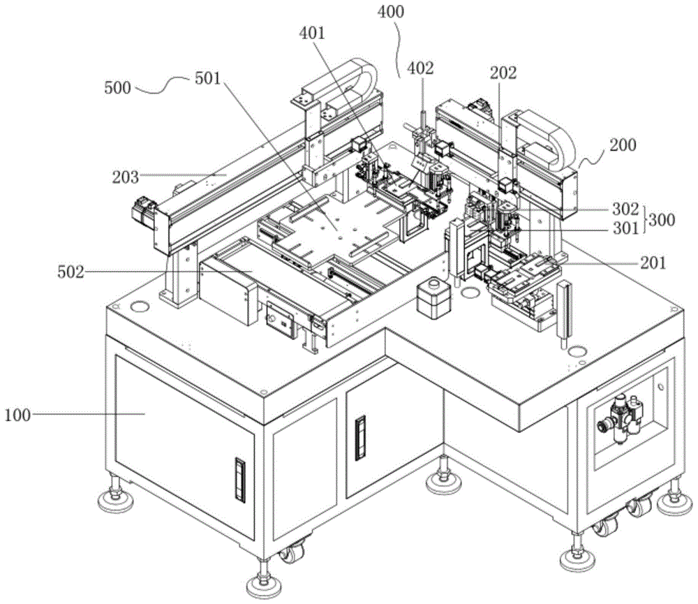
图1为一种电芯OCV测试机的结构示意图。FIG. 1 is a schematic structural diagram of a cell OCV testing machine.
图2为一种电芯OCV测试机中测试平台的结构示意图。FIG. 2 is a schematic structural diagram of a testing platform in a cell OCV testing machine.
图3为一种电芯OCV测试机中测试单元的结构示意图。FIG. 3 is a schematic structural diagram of a testing unit in a cell OCV testing machine.
图4为一种电芯OCV测试机中第一移料件的结构示意图。FIG. 4 is a schematic structural diagram of a first moving part in a cell OCV testing machine.
图5为一种电芯OCV测试机中第二移料件的结构示意图。FIG. 5 is a schematic structural diagram of a second moving part in a cell OCV testing machine.
图6为一种电芯OCV测试机中第三移料件的结构示意图。FIG. 6 is a schematic structural diagram of a third moving part in a cell OCV testing machine.
图7为一种电芯OCV测试机中良品出料机构的结构示意图。FIG. 7 is a schematic structural diagram of a good product discharging mechanism in a cell OCV testing machine.
图8为一种电芯OCV测试机中不良品出料机构的结构示意图。FIG. 8 is a schematic structural diagram of a defective product discharging mechanism in a cell OCV testing machine.
图9为一种电芯OCV测试机中定位平台的结构示意图。FIG. 9 is a schematic structural diagram of a positioning platform in a cell OCV testing machine.
图10为一种电芯OCV测试机中扫码机构的结构示意图。FIG. 10 is a schematic structural diagram of a code scanning mechanism in a cell OCV testing machine.
图11为一种电芯OCV测试机中上架体的结构示意图。FIG. 11 is a schematic structural diagram of an upper frame body in a cell OCV testing machine.
图中:100-机架、101-工控电脑显示器、102-键盘鼠标位、103-OCV测试仪、104-触摸屏、105-报警灯、106-脚轮、107-气源过滤器、108-脚杯、200-移料装置、201-第一移料件、2011-底座I、2012-旋转气缸、2013-旋转气缸连接板、2014-电芯底部绝缘板、2015-电芯正负极绝缘板、2016-真空吸盘I、2017-电芯左右调节挡板、202-第二移料件、2021-底座II、2022-竖支撑板I、2023-加强筋I、2024-下封板I、2025-侧封板I、2026-横板支撑板I、2027-活动组竖板I、2028-拖链I、2029-伺服电机I、20210-拖链支架I、20211-上封板I、20212-中封板I、20213-真空表I、20214-吸盘组安装横板I、20215-气缸安装板I、20216-上下气缸I、20217-吸盘安装板I、20218-真空吸盘II、203-第三移料件、2031-底座III、2032-竖支撑板II、2033-加强筋II、2034-侧封板II、2035-伺服电机II、2036-拖链支架II、2037-活动组竖板II、2038-拖链II、2039-上封板II、20310-中封板II、20311-下封板II、20312-真空表II、20313-气缸安装板II、20314-上下气缸II、20315-吸盘安装板II、20316-真空吸盘III、20317-吸盘组安装横板II、20318-横板支撑板II、300-OCV测试装置、301-测试平台、3011-竖支撑板III、3012-电芯放料板、3013-吸盘安装板III、3014-真空吸盘IV、3015-下导电件、3016-下导电件绝缘板、3017-上下调节板、3018-上下调节固定板、302-测试单元、3021-底座IV、3022-上下气缸III、3023-上导电件、3024-上下活动滑轨滑块、3025-竖支撑板IV、3026-左右滑块连接板、3027-左右调节滑轨滑块、400-扫描装置、401-定位平台、4011-竖支撑板V、4012-平台绝缘面板、4013-修正气缸、4014-修正绝缘板、4015-钢化透明玻璃、4016-光纤传感器I、4017-光纤安装板I、4018-气缸安装支架、402-扫码机构、4021-底座V、4022-支撑杆、4023-扫码枪、4024-调节块I、4025-调节杆I、4026-扫码枪安装座、4027-调节杆II、4028-调节块II、500-出料装置、501-良品出料机构、5011-侧封板III、5012-伺服电机III、5013-托盘、5014-托盘调节板、5015-托盘平台板、5016-感应开关、5017-感应开关安装铝条、502-不良品出料机构、5021-底座VI、5022-前后封板、5023-右侧板、5024-绝缘板、5025-皮带、5026-电机外绝缘板、5027-电机、5028-电机调速器、5029-调速器安装板、50210-左侧板、50211-光纤安装板II、50212-光纤传感器II。In the picture: 100-rack, 101-industrial computer monitor, 102-keyboard and mouse, 103-OCV tester, 104-touch screen, 105-alarm light, 106-caster, 107-air filter, 108-foot cup , 200-material moving device, 201-first material moving part, 2011-base I, 2012-rotating cylinder, 2013-rotating cylinder connecting plate, 2014-battery bottom insulating plate, 2015-battery positive and negative insulating plate, 2016-Vacuum sucker I, 2017-Cell left and right adjustment baffle, 202-Second moving part, 2021-Base II, 2022-Vertical support plate I, 2023-Reinforcing rib I, 2024-Lower sealing plate I, 2025- Side sealing plate I, 2026-horizontal plate support plate I, 2027-moving group vertical plate I, 2028- drag chain I, 2029-servo motor I, 20210- drag chain support I, 20211-upper sealing plate I, 20212-middle Sealing plate I, 20213-vacuum meter I, 20214-suction cup group installation horizontal plate I, 20215-cylinder installation plate I, 20216-up and down cylinder I, 20217-suction cup installation plate I, 20218-vacuum suction cup II, 203-third shift Material, 2031-Base III, 2032-Vertical Support Plate II, 2033-Reinforcing Rib II, 2034-Side Sealing Plate II, 2035-Servo Motor II, 2036-Drag Chain Bracket II, 2037-Active Group Vertical Plate II, 2038 -Drag Chain II, 2039-upper sealing plate II, 20310-middle sealing plate II, 20311-lower sealing plate II, 20312-vacuum gauge II, 20313-cylinder mounting plate II, 20314-upper and lower cylinder II, 20315-suction cup mounting plate II, 20316-Vacuum Suction Cup III, 20317-Suction Cup Group Installation Horizontal Plate II, 20318- Horizontal Plate Support Plate II, 300-OCV Test Device, 301-Test Platform, 3011-Vertical Support Plate III, 3012-Cell Discharge Plate , 3013-suction cup mounting plate III, 3014-vacuum suction cup IV, 3015-lower conductor, 3016-lower conductor insulation plate, 3017-up and down adjustment plate, 3018-up and down adjustment fixing plate, 302-test unit, 3021-base IV , 3022-up and down cylinder III, 3023-upper conductive part, 3024-up and down movable slide rail slider, 3025-vertical support plate IV, 3026-left and right slider connecting plate, 3027-left and right adjustment slide rail slider, 400-scanning device , 401-positioning platform, 4011-vertical support plate V, 4012-platform insulation panel, 4013-correction cylinder, 4014-correction insulating plate, 4015-tempered transparent glass, 4016-fiber sensor I, 4017-fiber mounting plate I, 4018 -Cylinder mounting bracket, 402-scanning mechanism, 4021-base V, 4022-support rod, 4023-scanning gun, 4024- Adjustment block I, 4025-adjustment rod I, 4026-scanning gun mount, 4027-adjustment rod II, 4028-adjustment block II, 500-discharge device, 501-good product discharge mechanism, 5011-side sealing plate III, 5012-Servo motor III, 5013-Pallet, 5014-Pallet adjustment plate, 5015-Pallet platform plate, 5016-Induction switch, 5017-Induction switch installation aluminum strip, 502-Defective product discharge mechanism, 5021-Base VI, 5022- Front and rear sealing plates, 5023-right side plate, 5024-insulation plate, 5025-belt, 5026-motor outer insulation plate, 5027-motor, 5028-motor governor, 5029-speed governor mounting plate, 50210-left side plate , 50211 - Fiber Optic Mounting Plate II, 50212 - Fiber Optic Sensor II.
具体实施方式Detailed ways
这里将详细地对示例性实施例进行说明,其示例表示在附图中。下面的描述涉及附图时,除非另有表示,不同附图中的相同数字表示相同或相似的要素。以下示例性实施例中所描述的实施方式并不代表与本公开相一致的所有实施方式。相反,它们仅是与如所附权利要求书中所详述的、本实施例公开的一些方面相一致的装置和方法的例子。Exemplary embodiments will be described in detail herein, examples of which are illustrated in the accompanying drawings. Where the following description refers to the drawings, the same numerals in different drawings refer to the same or similar elements unless otherwise indicated. The implementations described in the illustrative examples below are not intended to represent all implementations consistent with this disclosure. Rather, they are merely examples of apparatus and methods consistent with the aspects disclosed in the present embodiments, as recited in the appended claims.
请参阅图1,本发明实施例中,一种电芯OCV测试机,包括机架100、OCV测试装置300、扫描装置400、出料装置500、移料装置200以及控制装置,其中,所述OCV测试装置300安装在机架100上,用于对电芯进行OCV测试;所述扫描装置400设置在机架100上,用于对电芯进行数据采集;所述出料装置500安装在机架100上,用于对经OCV测试后得到的良品和不良品进行分开出料;所述移料装置200安装在机架100上,用于带动电芯在OCV测试装置300、扫描装置400和出料装置500之间的转移;所述控制装置用于控制上述部件,优选的,控制装置可以为可编程逻辑控制器,优选为西门子600系列,其主要实现是上述各个部件之间的协调工作。Referring to FIG. 1, in an embodiment of the present invention, a cell OCV testing machine includes a
在实际应用时,移料装置200将电芯送入到OCV测试装置300内进行OCV测试,之后移料装置200再将经过测试完成后的电芯放入到扫描装置400上,进行数据的采集,这里的数据采集可以保证电芯的生产日期、条码、相关参数等,而且经过测试后的电芯可以得知其属于良品或不良品,良品和不良品由移料装置200送入到出料装置500中进行分开出料。In practical application, the
其可以实现对电芯OCV测试的自动化高效运行,基本不需要人员参与即可进行测试,自动化程度高。It can realize the automatic and efficient operation of the cell OCV test, and the test can be carried out basically without the participation of personnel, and the degree of automation is high.
请参阅图2~3,作为本发明一个优选的实施例,所述OCV测试装置包括测试平台301和测试单元302,所述测试平台301安装在机架上,用于放置电芯并对电芯进行定位;所述测试单元302与测试平台301位置对应,本实施例中,测试单元302与测试平台301在竖直方向上的投影重合,以实现位置对应,通过电路导通机构与测试平台301耦合,实现电路通断。Please refer to FIGS. 2 to 3. As a preferred embodiment of the present invention, the OCV test device includes a
移料装置200将电芯送入到OCV测试装置300中的测试平台301后,定位在测试平台301内,之后测试单元302通过电路导通机构与测试平台301耦合,实现电路通断,当电路导通时,电芯通电,OCV测试仪可以对电芯进行正常测试。具体的来说:After the moving
所述电路导通机构包括分处于测试平台301和测试单元302上的、成对设置的导电件,其中一个所述导电件由驱动机构驱动使其与导电件接触或脱离;所述测试平台301包括放料件和定位件,其中所述放料件用于放置电芯,放料件上还设有用于隔离电芯引脚的隔离件,安装在所述放料件上的定位件用于对电芯进行定位。The circuit conduction mechanism includes conductive members arranged in pairs on the
所述放料件包括电芯放料板3012,电芯放料板3012的底部安装有吸盘安装板III3013,吸盘安装板III3013的底部通过竖支撑板III3011安装在机架100上,而对于定位件来说,本实施例将真空吸盘IV3014作为定位件,电芯放料板3012上设有对真空吸盘IV3014的让位孔,使得电芯在放入至电芯放料板3012上时,真空吸盘IV3014能保证电芯与电芯放料板3012的吸和状态,实现定位效果。The discharging member includes a
对于本实施例中的成对设置的导电件,其可以为导电触点式的结构,也可以为本实施例附图所示的下导电件3015和上导电件3023,其中,所述下导电件3015处于竖支撑板III3011的一侧位置,其数量为两个,中间使用隔离件隔开,隔离件可以为绝缘材质制成的板状结构,两个下导电件3015分别为正负极,也分别与电芯的两个引脚对应;For the conductive members arranged in pairs in this embodiment, it may be a conductive contact type structure, or may be the lower
进一步的来说,本实施例中,所述下导电件3015的高低位置可调,以保证导电件能与电芯引脚良好的接触,具体的,所述下导电件3015安装在上下调节板3017上并处于竖支撑板III3011的一侧位置,上下调节板3017与竖支撑板III3011滑动配合且通过上下调节固定板锁紧定位,当然,下导电件3015与上下调节板3017之间设有下导电件绝缘板3016。Further, in this embodiment, the height of the lower
而对于上导电件3023来说,所述上导电件3023的数量与下导电件3015是相对的,本实施例中,使用上下气缸III3022作为驱动机构,当然也可以使用电缸、液压缸等其他具有移动功能的装置,上导电件3023由上下气缸III3022驱动升降,此外,为了保证升降的顺畅性以及直线度,所述上导电件3023还通过上下活动滑轨滑块3024与竖支撑板IV3025滑动配合,竖支撑板IV3025和上下气缸III3022均安装在左右滑块连接板3026上,左右滑块连接板3026通过左右调节滑轨滑块3027与底座IV3021滑动配合,即上导电件3023在实际应用时不仅可以实现升降功能,还能实现水平位置的微调,以保证下导电件3015和上导电件3023的良好接触。As for the upper
在实际应用时,下导电件3015和上导电件3023相当于是一个开关结构,主要实现的是对电芯的通断电,以方便OCV测试仪对电芯进行测试。In practical application, the lower
请参阅图7~8,作为本发明另一个优选的实施例,所述出料装置包括良品出料机构501以及不良品出料机构502,所述良品出料机构501安装在机架上并处于移料装置的行程范围内,用于储放良品电芯及将良品电芯输出;所述不良品出料机构502安装在机架上并处于移料装置的行程范围内,用于储放不良品电芯及将不良品电芯输出。7-8, as another preferred embodiment of the present invention, the discharging device includes a good
由于经过OCV测试仪的测量之后,电芯的质量判断可以完成,即可以将经过OCV测试仪测试之后的电芯分为良品或不良品,而此时,可以利用移料张志200将良品或不良品电芯分别送入到良品出料机构501和不良品出料机构502以实现输出。After the measurement of the OCV tester, the quality judgment of the cells can be completed, that is, the cells tested by the OCV tester can be classified into good or bad products. The defective battery cells are respectively fed into the good
所述良品出料机构501包括储料件以及移动机构,所述储料件,由移动机构驱动,用于储放良品电芯;所述移动机构安装在机架上,用于驱动储料件移动以实现储料件内良品电芯的输出,并在储料件移动到位后停机;所述不良品出料机构502为输送带,且在输送带上的不良品电芯运动到位后停机。The good
具体的来说,对于储料件来说,本实施例以托盘5013作为储料件,当然也可以使用其他具有储料功能的部件,作为优选的,托盘5013还可以设置多个定位腔来放料,托盘5013通过托盘调节板5014安装在托盘平台板5015上。Specifically, for the material storage part, the
对于移动机构来说,实际上来讲具有带动储料件移动的功能的部件均可,本实施例乙提供了一种移动机构的优选结构,所述移动机构包括伺服电机III5012,所述伺服电机III5012安装在由若干侧封板III5011合围成的安装框上,储料件由伺服电机III5012驱动移动,具体的,可以通过滚珠丝杆组件、传送带组件等方式来实现带动储料件移动,当前,储料件中的托盘平台板5015与安装框滑动配合。For the moving mechanism, in fact, any component that has the function of driving the storage member to move can be used. This embodiment B provides a preferred structure of a moving mechanism. The moving mechanism includes a servo motor III5012. The servo motor III5012 It is installed on the installation frame enclosed by several side sealing plates III5011, and the storage part is driven by the servo motor III5012 to move. Specifically, the movement of the storage part can be realized by means of a ball screw assembly, a conveyor belt assembly, etc. Currently, the storage part is moved. The
此外,为了实现储料件在移动到位后能自动停机,本实施例设有感应开关5016,感应开关5016通过感应开关安装铝条5017安装在安装框上。In addition, in order to realize the automatic shutdown of the material storage piece after moving in place, the present embodiment is provided with an
对于不良品出料机构502来说,实际上,其也可以与良品出料机构501结构相同,也可以与良品出料机构501结构不相同,本实施例中,公开了不良品出料机构502为输送带,具体的来说,所述输送带包括底座VI5021、电机5027和电机调速器5027,电机5027安装在由前后封板5022、右侧板5023和左侧板50210围合而成的输送架上,输送架通过底座VI5021安装在机架100上,电机5027用于带动输送架内的皮带5025运动,电机调速器5027通过调速器安装板5029安装在输送架上,电机调速器5027用于调整电机5027的转动速度;而且由于电芯易受到静电的影响造成损坏,本实施例在前后封板5022、右侧板5023和左侧板50210的外部均设有绝缘板5024,以及在电机5027的外部设有电机外绝缘板5026,以减少静电对电芯造成的影响。For the defective
此外,所述输送架上还通过光纤安装板II50211安装有光纤传感器II50212,以实现不良品电芯运动到位后的自动停机。In addition, the optical fiber sensor II50212 is also installed on the conveying frame through the optical fiber mounting plate II50211, so as to realize the automatic shutdown after the defective cell moves in place.
请参阅图4~6,作为本发明另一个优选的实施例,所述移料装置包括第一移料件201、第二移料件202和第三移料件203,所述第一移料件201安装在机架上,用于对电芯进行定位和姿态调整,使其上的电芯以设定姿态被第二移料件取放;所述第二移料件202安装在机架上,用于将电芯从第一移料件201上以设定姿态转移至OCV测试装置上进行OCV测试,和将OCV测试装置上的电芯转移至扫描装置上进行数据采集;所述第三移料件203,安装在机架上,用于根据OCV测试装置的判定结果,将扫描装置上的电芯放入至良品出料机构501或不良品出料机构502上。4 to 6, as another preferred embodiment of the present invention, the material moving device includes a first
对于第一移料件201来说,所述第一移料件201包括底座I2011、旋转气缸2012和旋转气缸连接板2013,旋转气缸2012安装在底座I2011上,旋转气缸2012的输出端安装有旋转气缸连接板2013,旋转气缸连接板2013上固定有电芯底部绝缘板2014,电芯底部绝缘板2014上设有若干对电芯左右调节挡板2017,其中电芯左右调节挡板2017与电芯底部绝缘板2014之间的相对位置可调,即通过调节两个电芯左右调节挡板2017之间的距离可以对电芯进行定位,同时能调整电芯的姿态,当然了,所述旋转气缸连接板2013或电芯底部绝缘板2014上设有电芯正负极绝缘板2015,此处的电芯正负极绝缘板2015即相当于上述的隔离件,其主要是对电芯的两个引脚进行隔离,以防止引脚受损的问题发生,此处,所述电芯底部绝缘板2014上还安装有真空吸盘I2016,用来对电芯进行吸紧定位。For the first moving
实际应用时,可以通过人工手动将电芯放入到两个电芯左右调节挡板2017之间,之后真空吸盘I2016启动,在两者的配合下对电芯进行定位并实现姿态的调整,之后供第二移料件202取出,然后旋转气缸2012带动其转动180度,再进行另一位置处电芯的取料,当然,转动180度的前提是电芯底部绝缘板2014上设有两组真空吸盘I2016及电芯左右调节挡板2017,其可以根据实际需求做出适应性改变。In practical application, the battery cell can be manually placed between the left and right adjustment baffles 2017 of the two battery cells, and then the vacuum suction cup I2016 is activated. For taking out the second material-moving
对于第二移料件202来说,其包括底座II2021、拖链I2028、伺服电机I2019和上下气缸I20216,所述伺服电机I2019安装在由下封板I2024、侧封板I2025、上封板I20211和中封板I20212围合成的移料机架I上,移料机架I通过竖支撑板I2022安装在底座II2021上,当然为了增加强度,所述竖支撑板I2022上设有加强筋I2023,所述拖链I2028由伺服电机I2019驱动,所述拖链I2028底部的拖链支架I20210通过活动组竖板I2027与横板支撑板I2026连接,横板支撑板I2026与吸盘组安装横板I20214固定连接,所述吸盘组安装横板I20214安装有一对气缸安装板I20215,每个所述气缸安装板I20215上均安装有上下气缸I20216,上下气缸I20216的输出端安装通过吸盘安装板I20217安装有真空吸盘II20218;作为优选的,所述移料机架I上安装有真空表I20213,用来显示气路的压力;For the second
此处,由于第二移料件202同时需要将第一移料件201上的电芯移动至OCV测试装置300上,也需要将OCV测试装置300已经测试完成的电芯移动至扫描装置400上,因此,真空吸盘II20218和上下气缸I20216的数量均需要为一对,在实际应用时,当真空吸盘II20218运动至电芯的正上方时,上下气缸I20216带动真空吸盘II20218下降,真空吸盘II20218吸取电芯,之后上下气缸I20216带动真空吸盘II20218及电芯上升,再由拖链I2028带动电芯运动至OCV测试装置300或扫描装置400上。Here, since the second moving
对于第三移料件203来说,其包括底座III2031、拖链II2038、伺服电机II2035和气缸安装板II20313,所述伺服电机II2035安装在由下封板II20311、侧封板II2034、上封板II2039和中封板II20310围合成的移料机架II上,移料机架II通过竖支撑板II2032安装在底座III2031上,当然为了增加强度,所述竖支撑板II2032上设有加强筋II2033,所述拖链I2028由伺服电机I2019驱动,所述拖链II2038底部的拖链支架II2036通过活动组竖板II2037和横板支撑板II20318与吸盘组安装横板II20317连接,For the third moving
所述吸盘组安装横板II20317安装有气缸安装板II20313,所述气缸安装板II20313上均安装有上下气缸II20314,上下气缸II20314的输出端安装通过吸盘安装板II20315安装有真空吸盘III20316;作为优选的,所述移料机架II上安装有真空表II20312,用来显示气路的压力。The suction cup group installation horizontal plate II20317 is installed with a cylinder installation plate II20313, the cylinder installation plate II20313 is equipped with an upper and lower cylinder II20314, and the output end of the upper and lower cylinder II20314 is installed through the suction cup installation plate II20315 is installed with a vacuum suction cup III20316; as a preferred option , a vacuum gauge II20312 is installed on the moving rack II, which is used to display the pressure of the gas circuit.
实际上,第二移料件202和第三移料件203的区别在于,第二移料件202上设有两组上下气缸和真空吸盘,而第三移料件203仅设置有一组,其他并无区别。In fact, the difference between the second
请参阅图9~10,作为本发明另一个优选的实施例,所述扫描装置包括定位平台401和扫码机构402,其中所述定位平台401安装在机架上,用于在感知到电芯后,对其上的电芯进行位置修正;所述扫码机构402与定位平台401位置对应,用于对定位平台401上的电芯扫码以实现数据采集;作为优选的,所述扫码机构402包括扫码枪4023,当然也可以其他具有扫码或扫描的设备,所述扫码枪4023的水平位置、竖直位置和倾角均可调。Referring to FIGS. 9-10, as another preferred embodiment of the present invention, the scanning device includes a
具体的来说,所述定位平台401包括平台绝缘面板4012、修正气缸4013和修正绝缘板4014,所述平台绝缘面板4012的相对侧上均通过气缸安装支架4018安装有修正气缸4013,修正气缸4013的输出端连接有修正绝缘板4014,平台绝缘面板4012上嵌入有钢化透明玻璃4015,当然,平台绝缘面板4012上还通过光纤安装板I4017安装有光纤传感器I4016,用来感知钢化透明玻璃4015上是否存在有电芯,修正绝缘板4014由于是相对布置的,并且位置通过修正气缸4013来调节,其可以用来调整或修正电芯的位置,便与其能被扫码机构402进行扫码以实现数据采集,平台绝缘面板4012通过竖支撑板V4011安装在机架100上。Specifically, the
对于扫码机构402来说,所述扫码枪4023安装在扫码枪安装座4026上,扫码枪安装座4026转动安装在调节杆II4027上,调节杆II4027转动安装在调节块II4028上,调节块II4028上转动安装有调节杆I4025,调节杆I4025转动安装在调节块I4024上,调节块I4024上转动安装有支撑杆4022,支撑杆4022通过底座V4021安装在机架100上,此处,转动安装的方式是在对应的调节块或安装座上设开口槽或开口孔,对应的调节杆插入至开口槽或开口孔内,然后通过螺钉或螺栓锁紧的方式,实现转动安装,最终实现扫码枪4023的水平位置、竖直位置和倾角均可调。For the
请参阅图11,作为本发明另一个优选的实施例,所述机架100上还固定有上架体,一般来说,上架体采用型材焊接或螺栓连接即可,上架体上可以放置工控电脑显示器101、键盘鼠标位102、OCV测试仪103、触摸屏104和报警灯105等装置,特别是对于OCV测试仪103来说,当其设置在上架体上时,OCV测试装置300相当于是一个定位夹具,用来对电芯进行定位,通过电路导通机构实现电芯与OCV测试仪103的连接,而其也可以不设置在上架体上,即与OCV测试装置300集成为一体,具体的不做限定;对于工控电脑显示器101来说,与其连接的工控电脑相当于本技术方案的控制系统,由于本技术方案未对其进行改进,因此,本技术方案中各个部件如气缸、真空吸盘、电机等部件与其的连接和控制关系就不多做说明了。Please refer to FIG. 11, as another preferred embodiment of the present invention, an upper frame body is also fixed on the
对于机架100来说,其底部安装有若干个脚轮106和脚杯108,所述机架100上还可以安装有气源过滤器107,用来对气缸、真空吸盘等气动部件气路中的气源进行过滤。For the
本发明上述实施例公开了一种电芯OCV测试机,其可以对电芯进行自动化OCV测试以及扫码、不良品的区分放料以及电芯在各个功能单元内的自动转移,以自动测试电压、电阻、K值等数据,进而实现良品和不良品的筛分,其可以实现对电芯OCV测试的自动化高效运行,基本不需要人员参与即可进行测试,自动化程度高。并且,其控制系统还可以与本地及联网数据共享,实现数据分析处理的功能。The above-mentioned embodiment of the present invention discloses an OCV testing machine for battery cells, which can perform automatic OCV testing on the battery cells, scan codes, distinguish and discharge defective products, and automatically transfer the battery cells in each functional unit to automatically test the voltage. , resistance, K value and other data, and then realize the screening of good and bad products, which can realize the automatic and efficient operation of the OCV test of the battery cell, which basically does not require personnel to participate in the test, and has a high degree of automation. In addition, its control system can also share with local and networked data to realize the function of data analysis and processing.
本领域技术人员在考虑说明书及实施例处的公开后,将容易想到本公开的其它实施方案。本申请旨在涵盖本公开的任何变型、用途或者适应性变化,这些变型、用途或者适应性变化遵循本公开的一般性原理并包括本公开未公开的本技术领域中的公知常识或惯用技术手段。说明书和实施例仅被视为示例性的,本公开的真正范围和精神由权利要求指出。Other embodiments of the present disclosure will readily occur to those skilled in the art upon consideration of the disclosure at the specification and examples. This application is intended to cover any variations, uses, or adaptations of the present disclosure that follow the general principles of the present disclosure and include common knowledge or techniques in the technical field not disclosed by the present disclosure . The specification and examples are to be regarded as exemplary only, with the true scope and spirit of the disclosure being indicated by the claims.
应当理解的是,本公开并不局限于上面已经描述并在附图中示出的精确结构,并且可以在不脱离其范围进行各种修改和改变。本公开的范围仅由所附的权利要求来限制。It is to be understood that the present disclosure is not limited to the precise structures described above and illustrated in the accompanying drawings, and that various modifications and changes may be made without departing from the scope thereof. The scope of the present disclosure is limited only by the appended claims.
Claims (10)
Priority Applications (1)
| Application Number | Priority Date | Filing Date | Title |
|---|---|---|---|
| CN201911076267.8A CN110665858A (en) | 2019-11-06 | 2019-11-06 | Electricity core OCV test machine |
Applications Claiming Priority (1)
| Application Number | Priority Date | Filing Date | Title |
|---|---|---|---|
| CN201911076267.8A CN110665858A (en) | 2019-11-06 | 2019-11-06 | Electricity core OCV test machine |
Publications (1)
| Publication Number | Publication Date |
|---|---|
| CN110665858A true CN110665858A (en) | 2020-01-10 |
Family
ID=69086380
Family Applications (1)
| Application Number | Title | Priority Date | Filing Date |
|---|---|---|---|
| CN201911076267.8A Pending CN110665858A (en) | 2019-11-06 | 2019-11-06 | Electricity core OCV test machine |
Country Status (1)
| Country | Link |
|---|---|
| CN (1) | CN110665858A (en) |
Cited By (3)
| Publication number | Priority date | Publication date | Assignee | Title |
|---|---|---|---|---|
| CN111239623A (en) * | 2020-01-21 | 2020-06-05 | 重庆长安汽车股份有限公司 | Multichannel battery module OCV testing mechanism |
| CN111871860A (en) * | 2020-07-31 | 2020-11-03 | 广东利元亨智能装备股份有限公司 | A cell sorting device |
| CN114029241A (en) * | 2021-12-10 | 2022-02-11 | 山东爱德邦智能科技有限公司 | Soft-packaged electrical core material loading sorting facilities |
Citations (7)
| Publication number | Priority date | Publication date | Assignee | Title |
|---|---|---|---|---|
| CN107064810A (en) * | 2017-02-28 | 2017-08-18 | 惠州金源精密自动化设备有限公司 | A kind of battery core OCV test machines |
| CN107082243A (en) * | 2017-04-28 | 2017-08-22 | 浙江杭可科技股份有限公司 | Soft package lithium battery automatic charging & discharging machine |
| CN207007128U (en) * | 2017-07-10 | 2018-02-13 | 东莞新易科电子有限公司 | Battery core size automatic checkout equipment |
| CN108043740A (en) * | 2017-12-13 | 2018-05-18 | 惠州金源精密自动化设备有限公司 | Battery core OCV test equipments and its test method |
| CN108568410A (en) * | 2018-05-17 | 2018-09-25 | 张金仙 | A kind of lithium battery screening installation |
| CN109894392A (en) * | 2019-03-06 | 2019-06-18 | 肇庆遨优动力电池有限公司 | Soft pack cell sorting unit and method |
| CN211070927U (en) * | 2019-11-06 | 2020-07-24 | 深圳市大程智控科技有限公司 | Electricity core OCV test machine |
-
2019
- 2019-11-06 CN CN201911076267.8A patent/CN110665858A/en active Pending
Patent Citations (7)
| Publication number | Priority date | Publication date | Assignee | Title |
|---|---|---|---|---|
| CN107064810A (en) * | 2017-02-28 | 2017-08-18 | 惠州金源精密自动化设备有限公司 | A kind of battery core OCV test machines |
| CN107082243A (en) * | 2017-04-28 | 2017-08-22 | 浙江杭可科技股份有限公司 | Soft package lithium battery automatic charging & discharging machine |
| CN207007128U (en) * | 2017-07-10 | 2018-02-13 | 东莞新易科电子有限公司 | Battery core size automatic checkout equipment |
| CN108043740A (en) * | 2017-12-13 | 2018-05-18 | 惠州金源精密自动化设备有限公司 | Battery core OCV test equipments and its test method |
| CN108568410A (en) * | 2018-05-17 | 2018-09-25 | 张金仙 | A kind of lithium battery screening installation |
| CN109894392A (en) * | 2019-03-06 | 2019-06-18 | 肇庆遨优动力电池有限公司 | Soft pack cell sorting unit and method |
| CN211070927U (en) * | 2019-11-06 | 2020-07-24 | 深圳市大程智控科技有限公司 | Electricity core OCV test machine |
Non-Patent Citations (1)
| Title |
|---|
| 彭志忠: "《物流管理学》", 31 August 2005, 山东大学出版社, pages: 285 * |
Cited By (3)
| Publication number | Priority date | Publication date | Assignee | Title |
|---|---|---|---|---|
| CN111239623A (en) * | 2020-01-21 | 2020-06-05 | 重庆长安汽车股份有限公司 | Multichannel battery module OCV testing mechanism |
| CN111871860A (en) * | 2020-07-31 | 2020-11-03 | 广东利元亨智能装备股份有限公司 | A cell sorting device |
| CN114029241A (en) * | 2021-12-10 | 2022-02-11 | 山东爱德邦智能科技有限公司 | Soft-packaged electrical core material loading sorting facilities |
Similar Documents
| Publication | Publication Date | Title |
|---|---|---|
| CN111211064B (en) | A low-contact wafer centering and flipping system | |
| CN110369337A (en) | Light guide plate defective vision automatic checkout equipment and detection method | |
| CN110639848A (en) | A battery cell scanning code testing machine | |
| CN110125026A (en) | A kind of thickness-measuring equipment | |
| CN210742099U (en) | A testing machine that can measure six sides | |
| CN112161994A (en) | An AOI automatic optical detection loading and unloading machine | |
| CN111504390A (en) | A kind of battery comprehensive testing equipment | |
| CN110726481A (en) | Automatic test equipment for parameter performance of infrared focal plane array detector | |
| CN112683792A (en) | System for graphite flake appearance defects | |
| CN219173393U (en) | Bulk material vibration feeding, testing and sorting equipment | |
| CN114965283B (en) | Automatic feeding and discharging circuit board test equipment | |
| CN110860490A (en) | Full-automatic ox horn capacitor process monitoring aging machine | |
| CN116455325A (en) | Tool equipment for testing half-plate layout assembly | |
| CN210401600U (en) | Photovoltaic solar wafer IV detects machine | |
| CN213580726U (en) | Automatic optical inspection blanking machine of AOI | |
| CN211070927U (en) | Electricity core OCV test machine | |
| CN220160598U (en) | OLED module AOI detection equipment | |
| CN211359704U (en) | Full-automatic ox horn capacitor process monitoring aging machine | |
| CN108918538B (en) | A kind of reflective panel CCD detection equipment | |
| CN112730448A (en) | Graphite-attached black adhesive steel sheet edge glue overflow detection system | |
| CN220072495U (en) | Appearance detection device | |
| CN208818648U (en) | A kind of line sweeps formula AOI detection device | |
| CN208066784U (en) | A kind of external diameter detection device for auto parts and components | |
| CN207623355U (en) | A kind of full-automatic Defect Detection device | |
| CN211576998U (en) | An automatic capacitance full inspection machine |
Legal Events
| Date | Code | Title | Description |
|---|---|---|---|
| PB01 | Publication | ||
| PB01 | Publication | ||
| SE01 | Entry into force of request for substantive examination | ||
| SE01 | Entry into force of request for substantive examination | ||
| RJ01 | Rejection of invention patent application after publication | ||
| RJ01 | Rejection of invention patent application after publication |
Application publication date: 20200110 |