CN110653346A - Loading device for casting mold - Google Patents
Loading device for casting mold Download PDFInfo
- Publication number
- CN110653346A CN110653346A CN201910965881.3A CN201910965881A CN110653346A CN 110653346 A CN110653346 A CN 110653346A CN 201910965881 A CN201910965881 A CN 201910965881A CN 110653346 A CN110653346 A CN 110653346A
- Authority
- CN
- China
- Prior art keywords
- sliding
- plate
- fixedly connected
- supporting plate
- casting mold
- Prior art date
- Legal status (The legal status is an assumption and is not a legal conclusion. Google has not performed a legal analysis and makes no representation as to the accuracy of the status listed.)
- Pending
Links
- 238000005266 casting Methods 0.000 title claims abstract description 20
- 239000000725 suspension Substances 0.000 claims abstract description 7
- 230000005540 biological transmission Effects 0.000 claims description 4
- 238000009826 distribution Methods 0.000 claims 2
- 238000007789 sealing Methods 0.000 claims 1
- 238000009434 installation Methods 0.000 abstract description 5
- 230000000694 effects Effects 0.000 abstract description 4
- 238000000926 separation method Methods 0.000 abstract 1
- 238000000034 method Methods 0.000 description 7
- 239000012530 fluid Substances 0.000 description 2
- 230000005484 gravity Effects 0.000 description 2
- 239000007788 liquid Substances 0.000 description 2
- 230000001360 synchronised effect Effects 0.000 description 2
- 230000009286 beneficial effect Effects 0.000 description 1
- 239000000463 material Substances 0.000 description 1
- 230000004048 modification Effects 0.000 description 1
- 238000012986 modification Methods 0.000 description 1
- 230000000630 rising effect Effects 0.000 description 1
- 239000004576 sand Substances 0.000 description 1
- 239000002699 waste material Substances 0.000 description 1
Images


Classifications
-
- B—PERFORMING OPERATIONS; TRANSPORTING
- B22—CASTING; POWDER METALLURGY
- B22C—FOUNDRY MOULDING
- B22C23/00—Tools; Devices not mentioned before for moulding
-
- B—PERFORMING OPERATIONS; TRANSPORTING
- B22—CASTING; POWDER METALLURGY
- B22C—FOUNDRY MOULDING
- B22C7/00—Patterns; Manufacture thereof so far as not provided for in other classes
Landscapes
- Engineering & Computer Science (AREA)
- Mechanical Engineering (AREA)
- Casting Devices For Molds (AREA)
Abstract
The invention belongs to the technical field of mold loading, and particularly relates to a loading device for a casting mold, which comprises a lower supporting plate and an upper supporting plate rotatably connected above the lower supporting plate, wherein connecting rods are fixedly connected at four corners between the lower supporting plate and the upper supporting plate, each connecting rod comprises four supporting rods fixedly connected to the upper end surface of the upper supporting plate and four sliding rods fixedly connected to the bottom surface of the lower supporting plate, and the supporting rods and the sliding rods are in sliding connection; go up and connect through four connecting rods between backup pad and the bottom suspension fagging, when the installation mould, can directly take out three locating pin to a connecting rod is the center, other three bracing pieces and slide bar separation, thereby make and go up the backup pad and rotate with the bottom suspension fagging, go up the backup pad and rotate to one side, make the bottom suspension fagging expose completely, because the position height of bottom suspension fagging is lower, be convenient for this moment the installation mould just go up the backup pad and can not play the hindrance effect to the workman.
Description
Technical Field
The invention belongs to the technical field of mold loading, and particularly relates to a loading device for a casting mold.
Background
The casting mold is used for obtaining the structural shape of the part, other easily-formed materials are used for forming the structural shape of the part in advance, then the part is placed into the mold, a cavity with the same structural size as the part is formed in the sand mold, then the fluid liquid is poured into the cavity, and the part with the same structural shape as the mold can be formed after the fluid liquid is cooled and solidified. Casting molds are an important part of the casting process.
Chinese patent discloses a mold loading device, which is disclosed as (CN110000292A), and the device selects a mold as required, places the mold on a bracket, uses a lifting block to drive the bracket to rise, and simultaneously passes through a rail gap on a horizontal rail, and then loads the mold by using a mold loading mechanism, but as can be seen from fig. 1 of the above patent, the bracket is located below a workbench, and when an operator places the mold on the bracket, the operator is influenced by an upper workbench, so that the worker needs to squat for installation, and the squat worker is difficult to carry and transfer some heavier articles.
Disclosure of Invention
To solve the problems set forth in the background art described above. The invention provides a loading device for a casting mold, which has the characteristics of quick labor-saving assembly and wide application range.
In order to achieve the purpose, the invention provides the following technical scheme: a loading device for a casting mold comprises a lower supporting plate and an upper supporting plate rotatably connected above the lower supporting plate, connecting rods are fixedly connected at four corners between the lower supporting plate and the upper supporting plate, each connecting rod comprises four supporting rods fixedly connected to the upper end surface of the upper supporting plate and four sliding rods fixedly connected to the bottom surface of the lower supporting plate, the supporting rods and the sliding rods are all in sliding connection, the upper end surface of the lower supporting plate is in sliding connection with a lifting plate, the upper end surface of the lifting plate is provided with a limiting sliding chute, an operating plate is in sliding connection in the limiting sliding chute, the upper end surface of the operating plate is provided with two sliding rails, the two sliding rails are in sliding connection with a sliding platform, the upper end surface of the sliding platform is fixedly connected with a vertical plate, the vertical plate is in sliding connection with an upper moving, the driving cylinder is hermetically connected with an external air source, a clamping part is installed on one side of the upper moving plate, which is far away from the driving cylinder, and is electrically connected with an external power source, a horizontal translation motor is installed on one side of the upper end surface of the operating plate and is electrically connected with the external power source, a lead screw is fixedly connected with the output end of the horizontal translation motor, the vertical plate is in transmission connection with the horizontal translation motor through the lead screw, a lifting groove matched with the lifting plate is formed in the upper end surface of the upper supporting plate, a mounting plate is fixedly connected with one side of the upper supporting plate, a lifting motor is installed on the mounting plate and is electrically connected with the external power source, a connecting shaft is fixedly connected with the output end of the lifting motor, two containing rollers are fixedly connected on the connecting shaft, two guide rollers which are in a straight line with the containing rollers are, the take-in roller is fixedly connected with a traction rope, passes through the guide roller, and one end of the take-in roller is detachably connected with the lifting plate.
Preferably, be close to one of lifting motor the rotation hole has in the connecting rod, it sets up respectively to rotate the hole the bracing piece with the contact terminal surface of slide bar, it is connected with spacing rotating pin, other three to rotate downthehole rotation there is the locating pin in the connecting rod, sliding through hole has been seted up to the slide bar up end, sliding through hole is close to it is open structure to go up backup pad one end, spacing hole has been seted up to the bracing piece up end, sliding through hole with spacing downthehole sliding connection has the locating pin.
Preferably, the outer wall of the connecting rod is fixedly connected with limit guide rails, the limit guide rails are respectively positioned at four corners inside the lifting groove, and the four corners of the lifting plate are provided with matching grooves matched with the limit guide rails.
Preferably, the outer wall of the limiting guide rail is rotatably connected with a plurality of balls which are uniformly distributed.
Preferably, one end of the limiting chute is of an open structure, four limiting blocks which are symmetrically distributed are fixedly connected to the upper end face of the lifting plate, the limiting blocks are distributed on two sides of the limiting chute in a pairwise mode, and the operating plate is connected to the bottoms of the limiting blocks in a sliding mode.
Preferably, the open end of the limiting sliding groove is detachably connected with two limiting pins.
Preferably, one side of the upper supporting plate is provided with a sliding through groove matched with the operating plate.
Preferably, the upper end face of the lifting plate is fixedly connected with two symmetrically distributed support lugs, and the support lugs are located under the guide roller.
Preferably, one end of the accommodating roller is fixedly connected with a hook matched with the support lug.
Preferably, one end of the upper end surface of the lifting plate, which is far away from the open end of the limiting sliding groove, is fixedly connected with a handle.
Compared with the prior art, the invention has the beneficial effects that:
1. the upper supporting plate and the lower supporting plate are connected through four connecting rods, when the die is installed, three positioning pins can be directly taken out, one connecting rod is taken as a center, and other three supporting rods are separated from the sliding rod, so that the upper supporting plate and the lower supporting plate rotate, the upper supporting plate rotates to one side, the lower supporting plate is completely exposed, and the die is convenient to install and cannot be blocked by workers due to the fact that the lower supporting plate is low in position height;
2. after the lower supporting plate is completely exposed, the die can be directly placed on the upper end face of the operating plate, the upper supporting plate is reset after being clamped by the clamping component, then the traction rope is wound by the lifting motor, the lifting plate is lifted upwards, after lifting is finished, the operating plate can be directly pushed out from the lifting plate to the working table top to install the die, waste of operating space of the working table can be reduced by the method, and after the die is installed, the operating plate only needs to be retracted.
Drawings
The accompanying drawings, which are included to provide a further understanding of the invention and are incorporated in and constitute a part of this specification, illustrate embodiments of the invention and together with the description serve to explain the principles of the invention and not to limit the invention. In the drawings:
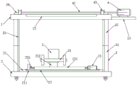
FIG. 1 is a schematic structural view of the present invention;
FIG. 2 is a schematic top view of the present invention;
FIG. 3 is an enlarged view of portion A of FIG. 2;
FIG. 4 is a schematic cross-sectional view of a connecting rod according to the present invention;
FIG. 5 is a schematic cross-sectional view of another tie rod of the present invention;
FIG. 6 is a schematic view of the mounting of the lug of the present invention;
fig. 7 is a schematic view of the rotation of the upper support plate in the present invention.
In the figure: 1. an upper support plate; 11. a lifting groove; 12. a sliding through groove; 13. mounting a plate; 2. a lower support plate; 21. a lifting plate; 211. a limiting chute; 212. a limiting block; 213. a spacing pin; 22. an operation panel; 221. a slide rail; 222. a vertical plate; 223. a sliding platform; 23. a horizontal translation motor; 231. a screw rod; 24. a handle; 25. a fitting groove; 3. a connecting rod; 31. a support bar; 311. a limiting hole; 32. a slide bar; 321. a slide through hole; 33. limiting a guide rail; 331. a ball bearing; 34. positioning pins; 35. rotating the hole; 36. a limiting rotating pin; 4. a lifting motor; 41. a connecting shaft; 42. a storage drum; 421. a hauling rope; 422. hooking; 43. a guide roller; 44. supporting a lug; 5. moving the plate upwards; 51. a clamping member; 52. the cylinder is driven.
Detailed Description
The technical solutions in the embodiments of the present invention will be clearly and completely described below with reference to the drawings in the embodiments of the present invention, and it is obvious that the described embodiments are only a part of the embodiments of the present invention, rather than all embodiments, and all other embodiments obtained by a person of ordinary skill in the art without creative efforts based on the embodiments of the present invention belong to the protection scope of the present invention, and for convenience of description, the description of the relative positional relationship of the components is described according to the layout manner of the drawings in the specification, such as: the positional relationship of front, rear, upper, lower, left, right, etc. is determined in accordance with the specification layout direction.
Referring to fig. 1-7, the present invention provides the following technical solutions: a loading device for a casting mold comprises a lower support plate 2 and an upper support plate 1 rotatably connected above the lower support plate 2, four corners between the lower support plate 2 and the upper support plate 1 are fixedly connected with connecting rods 3, each connecting rod 3 comprises four supporting rods 31 fixedly connected to the upper end surface of the upper support plate 1 and four sliding rods 32 fixedly connected to the bottom surface of the lower support plate 2, the supporting rods 31 and the sliding rods 32 are both slidably connected, the upper end surface of the lower support plate 2 is slidably connected with a lifting plate 21, the upper end surface of the lifting plate 21 is provided with a limiting sliding chute 211, the limiting sliding chute 211 is slidably connected with an operating plate 22, the upper end surface of the operating plate 22 is provided with two sliding rails 221, two sliding rails 221 are slidably connected with a sliding platform 223, the upper end surface of the sliding platform 223 is fixedly connected with a vertical plate 222, the vertical plate 222 is slidably connected with, the driving cylinder 52 is hermetically connected with an external air source, one side of the upper moving plate 5, which is far away from the driving cylinder 52, is provided with a clamping component 51, the clamping component 51 is electrically connected with an external power source, one side of the upper end surface of the operating plate 22 is provided with a horizontal translation motor 23, the horizontal translation motor 23 is electrically connected with the external power source, the output end of the horizontal translation motor 23 is fixedly connected with a screw rod 231, a vertical plate 222 is in transmission connection with the horizontal translation motor 23 through the screw rod 231, the upper end surface of the upper supporting plate 1 is provided with a lifting groove 11 matched with the lifting plate 21, one side of the upper supporting plate 1 is fixedly connected with a mounting plate 13, the mounting plate 13 is provided with a lifting motor 4, the lifting motor 4 is electrically connected with the external power source, the output end of the lifting motor 4 is fixedly connected with a connecting shaft 41, the, the accommodating roller 42 is fixedly connected with a traction rope 421, the accommodating roller 42 penetrates through the guide roller 43, and one end of the accommodating roller 42 is detachably connected with the lifting plate 21.
In this embodiment: the upper supporting plate 1 and the lower supporting plate 2 are connected through the connecting rod 3, the connecting rod 3 mainly comprises a supporting rod 31 and a sliding rod 32, the split structure can enable the upper supporting plate 1 and the lower supporting plate 2 to rotate by taking one of the connecting rods 3 as a center, the supporting rod 31 and the sliding rod 32 are separated when the supporting rod rotates, so that the lower supporting plate 2 is completely exposed, in actual use, one supporting frame can be matched for supporting the upper supporting plate 1 to prevent the situation that the whole body is inclined and turned over due to overhigh gravity center of the upper supporting plate 1, the lifting plate 21 on the upper end surface of the lower supporting plate 2 is mainly used for lifting a mold, the lifting plate 21 is provided with a limiting sliding groove 211 for limiting the operating plate 22 through the limiting sliding groove 211, the mold is arranged on the operating plate 22 and needs to be arranged on a workbench, so that when the mold is arranged, after being lifted by the lifting plate 21, the operation plate 22 is pushed out to the working table top to complete the die installation, the difficult problem of transferring to the working table top after being lifted can be effectively improved by the method, the labor intensity of an operator can be effectively reduced by a sliding method, the space occupation of the working table top can be reduced compared with a die loading structure installed on a re-working table top, the sliding rail 221 on the operation plate 22 has the effect of sliding limit on the sliding platform 223, the horizontal translation motor 23(YS-6314) can drive the screw rod 231 to rotate, the sliding platform 223 is driven to translate left and right on the sliding rail 221 through a screw rod transmission structure, the die is further adjusted in the horizontal direction, the die is fixedly connected to the clamping part 51, the clamping part 51 mainly utilizes a motor to drive a synchronous belt to move, and the two clamping plates are driven to be close to each other through the synchronous belt to clamp, the working principle of the clamping part 51 is the same as that of a mold loading mechanism in a mold loading device (with the publication number of CN110000292A) disclosed in Chinese patent, a cavity is arranged in the upper moving plate 5, a vertical plate 222 is positioned in the cavity, the upper moving plate 5 is driven to move up and down by a driving cylinder 52 (model: SC63) to install a mold, a traction rope 421 is detachably connected to the lifting plate 21, the storage roller 42 is driven to roll by the operation of a lifting motor 4, so that the traction rope 421 is wound on the storage roller 42 through a guide roller 43 to further pull up the upper moving plate 5, and the lifting motor 4 adopts a brake motor (model: MSEJ).
Specifically, a connecting rod 3 close to the lifting motor 4 is provided with a rotating hole 35, the rotating hole 35 is respectively arranged on the contact end surfaces of the supporting rod 31 and the sliding rod 32, a limiting rotating pin 36 is rotatably connected in the rotating hole 35, positioning pins 34 are slidably connected in the other three connecting rods 3, the upper end surface of the sliding rod 32 is provided with a sliding through hole 321, one end of the sliding through hole 321 close to the upper supporting plate 1 is of an open structure, the upper end surface of the supporting rod 31 is provided with a limiting hole 311, and the sliding through hole 321 and the limiting hole 311 are slidably connected with the positioning pin 34; connecting rod 3 that is close to lifting motor 4 is the center of rotation, lifting motor 4's weight is bigger, go up backup pad 1 and use near lifting motor 4 connecting rod 3 when being the center of rotation, lifting motor 4's position coordinate changes little, thereby can not influence the focus of backup pad 1 in the particular, the connecting rod 3 of center of rotation mainly carries on spacingly through spacing rotating pin 36, and other three connecting rod 3 mainly connect through locating pin 34, when locating pin 34 demolishs the back, slide bar 32 can separate with bracing piece 31, go up backup pad 1 and bottom suspension fagging 2 this moment and can take place to rotate.
Specifically, the outer walls of the connecting rods 3 are fixedly connected with limiting guide rails 33, the limiting guide rails 33 are respectively positioned at four corners inside the lifting groove 11, and the four corners of the lifting plate 21 are provided with fitting grooves 25 matched with the limiting guide rails 33; because the haulage rope 421 is fixed at the both ends of upper shift plate 5, can make the lifter plate 21 receive four points's slip spacing effect through four spacing guide rails 33 in the process of rising, improve the slip stability of lifter plate 21.
Specifically, the outer wall of the limit guide rail 33 is rotatably connected with a plurality of uniformly distributed balls 331; the balls 331 can reduce the friction between the lifting plate 21 and the stopper rail 33, thereby reducing the useless work.
Specifically, one end of the limiting sliding groove 211 is an open structure, the upper end face of the lifting plate 21 is fixedly connected with four symmetrically distributed limiting blocks 212, the limiting blocks 212 are distributed on two sides of the limiting sliding groove 211 in pairs, and the operating plate 22 is connected to the bottoms of the limiting blocks 212 in a sliding manner; the operation plate 22 cannot move up and down in the limit sliding groove 211 through the limit block 212, and the limit block 212 can be matched with some screws or limit nails to limit the sliding stroke of the operation plate 22, so that the sliding stability of the operation plate 22 is improved.
Specifically, the open end of the limiting chute 211 is detachably connected with two limiting pins 213; the limiting sliding groove 211 is provided with a hole matched with the limiting pin 213, and the operating panel 22 can be limited in the horizontal direction through the limiting pin 213, so that the operating panel 22 is prevented from sliding out.
Specifically, one side of the upper support plate 1 is provided with a sliding through groove 12 matched with the operating plate 22; since the operation panel 22 needs to slide out, when the lifting plate 21 is lifted and the operation panel 22 is pushed, the operation panel 22 can be directly slid out through the sliding through groove 12, so as to slide onto the working table.
Specifically, two symmetrically distributed support lugs 44 are fixedly connected to the upper end face of the lifting plate 21, and the support lugs 44 are located right below the guide roller 43; the support lug 44 can facilitate the fixing of the pulling rope 421, so that the pulling rope 421 can directly apply a force on the upper end surface of the lifting plate 21.
Specifically, one end of the receiving roller 42 is fixedly connected with a hook 422 matched with the support lug 44; can make more light convenient when dismantling through couple 422, need dismantle couple 422 when owing to go up backup pad 1 and rotate, can improve the convenience of dismantling through couple 422's the mode of articulating.
Specifically, one end of the upper end surface of the lifting plate 21, which is far away from the open end of the limiting chute 211, is fixedly connected with a handle 24; the handle 24 facilitates the operator pushing the operation panel 22.
The working principle and the using process of the invention are as follows: the upper supporting plate 1 and the lower supporting plate 2 are connected through the connecting rod 3, the connecting rod 3 mainly comprises a supporting rod 31 and a sliding rod 32, the split structure can enable the upper supporting plate 1 and the lower supporting plate 2 to rotate by taking one of the connecting rods 3 as a center, the supporting rod 31 and the sliding rod 32 are separated when the supporting rod rotates, so that the lower supporting plate 2 is completely exposed, in actual use, one supporting frame can be matched for supporting the upper supporting plate 1 to prevent the situation that the whole body is inclined and turned over due to overhigh gravity center of the upper supporting plate 1, the lifting plate 21 on the upper end surface of the lower supporting plate 2 is mainly used for lifting a mold, the lifting plate 21 is provided with a limiting sliding groove 211 for limiting the operating plate 22 through the limiting sliding groove 211, the mold is arranged on the operating plate 22 and needs to be arranged on a workbench, so that when the mold is arranged, after the lifting plate 21 is lifted, the operation plate 22 is pushed out to the working table top to complete the die installation, the difficult problem of transferring to the working table top after being lifted can be effectively improved by the method, the labor intensity of an operator can be effectively reduced by a sliding method, the space occupation of the working table top can be reduced compared with a die loading structure installed on the working table top, the sliding rail 221 on the operation plate 22 has the effect of sliding limiting on the sliding platform 223, the sliding platform 223 can be driven to horizontally move on the sliding rail 221 through driving the screw rod 231 to rotate, the die is horizontally adjusted by driving the sliding platform 223 to horizontally move, the die is fixedly connected to the clamping part 51, the cavity is arranged inside the upper moving plate 5, the vertical plate 222 is positioned in the cavity, the upper moving plate 5 is driven to move up and down through the driving cylinder 52 to install the die, and the lifting plate 21 is detachably connected with the traction rope, the lifting motor 4 works to drive the storage roller 42 to wind, so that the traction rope 421 is wound on the storage roller 42 through the guide roller 43, and the upper moving plate 5 is pulled up.
Finally, it should be noted that: although the present invention has been described in detail with reference to the foregoing embodiments, it will be apparent to those skilled in the art that changes may be made in the embodiments and/or equivalents thereof without departing from the spirit and scope of the invention. Any modification, equivalent replacement, or improvement made within the spirit and principle of the present invention should be included in the protection scope of the present invention.
Claims (10)
1. The utility model provides a loading attachment that casting mould was used, includes bottom suspension fagging (2) and rotates to be connected last backup pad (1) of bottom suspension fagging (2) top, its characterized in that: connecting rods (3) are fixedly connected at four corners between the lower supporting plate (2) and the upper supporting plate (1), each connecting rod (3) comprises four supporting rods (31) fixedly connected to the upper end surface of the upper supporting plate (1) and four sliding rods (32) fixedly connected to the bottom surface of the lower supporting plate (2), and the supporting rods (31) and the sliding rods (32) are connected in a sliding mode;
the upper end face of the lower supporting plate (2) is connected with a lifting plate (21) in a sliding manner, the upper end face of the lifting plate (21) is provided with a limiting sliding groove (211), the limiting sliding groove (211) is connected with an operating plate (22) in a sliding manner, two sliding rails (221) are installed on the upper end face of the operating plate (22), two sliding rails (221) are connected with a sliding platform (223) in a sliding manner, the upper end face of the sliding platform (223) is fixedly connected with a vertical plate (222), the vertical plate (222) is connected with an upper moving plate (5) in a sliding manner, a driving cylinder (52) is installed at the bottom of one side of the upper moving plate (5), the driving cylinder (52) is connected with an external air source in a sealing manner, the upper moving plate (5) is far away from one side of the driving cylinder (52) and is provided with a clamping part (51), the clamping part (51) is, the horizontal translation motor (23) is electrically connected with an external power supply, the output end of the horizontal translation motor (23) is fixedly connected with a screw rod (231), and the vertical plate (222) is in transmission connection with the horizontal translation motor (23) through the screw rod (231);
go up backup pad (1) up end seted up with lifter plate (21) complex lift groove (11), go up backup pad (1) one side fixedly connected with mounting panel (13), install lifting motor (4) on mounting panel (13), lifting motor (4) and external power source electric connection, lifting motor (4) output end fixedly connected with connecting axle (41), cylinder (42) are accomodate to two fixedly connected with on connecting axle (41), go up backup pad (1) both sides rotate be connected with two with accomodate cylinder (42) and be sharp guide roll (43), accomodate fixedly connected with haulage rope (421) on cylinder (42), accomodate cylinder (42) and pass guide roll (43), just accomodate cylinder (42) one end with the connection can be dismantled in lifter plate (21).
2. A loading apparatus for a casting mold as defined in claim 1, wherein: be close to one of lifting motor (4) rotation hole (35) have in connecting rod (3), it sets up respectively to rotate hole (35) bracing piece (31) with the contact surface of slide bar (32), it is connected with spacing rotating pin (36) to rotate hole (35) internal rotation, and other three sliding connection has locating pin (34) in connecting rod (3), sliding through-hole (321) have been seted up to slide bar (32) up end, sliding through-hole (321) are close to go up backup pad (1) one end and are open structure, spacing hole (311) have been seted up to bracing piece (31) up end, sliding through-hole (321) with sliding connection has locating pin (34) in spacing hole (311).
3. A loading apparatus for a casting mold as defined in claim 1, wherein: the equal fixedly connected with spacing guide rail (33) of connecting rod (3) outer wall, spacing guide rail (33) are located respectively lift groove (11) inside four corners department, lifter plate (21) four corners all seted up with spacing guide rail (33) complex agrees with groove (25).
4. A loading apparatus for a casting mold as defined in claim 3, wherein: the outer wall of the limiting guide rail (33) is rotatably connected with a plurality of uniformly distributed balls (331).
5. A loading apparatus for a casting mold as defined in claim 1, wherein: spacing spout (211) one end is open structure, four symmetric distribution's stopper (212) of lifter plate (21) up end fixedly connected with, two liang of distributions of stopper (212) are in the both sides of spacing spout (211), operation panel (22) sliding connection be in stopper (212) bottom.
6. A loading apparatus for a casting mold as defined in claim 1, wherein: the open end of the limiting sliding groove (211) is detachably connected with two limiting pins (213).
7. A loading apparatus for a casting mold as defined in claim 1, wherein: and one side of the upper supporting plate (1) is provided with a sliding through groove (12) matched with the operating plate (22).
8. A loading apparatus for a casting mold as defined in claim 1, wherein: two symmetrically distributed support lugs (44) are fixedly connected to the upper end face of the lifting plate (21), and the support lugs (44) are located under the guide roller (43).
9. A loading apparatus for a casting mold as defined in claim 8, wherein: one end of the accommodating roller (42) is fixedly connected with a hook (422) matched with the support lug (44).
10. A loading apparatus for a casting mold as defined in claim 1, wherein: the handle (24) is fixedly connected to one end, far away from the open end of the limiting sliding groove (211), of the upper end face of the lifting plate (21).
Priority Applications (1)
| Application Number | Priority Date | Filing Date | Title |
|---|---|---|---|
| CN201910965881.3A CN110653346A (en) | 2019-10-12 | 2019-10-12 | Loading device for casting mold |
Applications Claiming Priority (1)
| Application Number | Priority Date | Filing Date | Title |
|---|---|---|---|
| CN201910965881.3A CN110653346A (en) | 2019-10-12 | 2019-10-12 | Loading device for casting mold |
Publications (1)
| Publication Number | Publication Date |
|---|---|
| CN110653346A true CN110653346A (en) | 2020-01-07 |
Family
ID=69040705
Family Applications (1)
| Application Number | Title | Priority Date | Filing Date |
|---|---|---|---|
| CN201910965881.3A Pending CN110653346A (en) | 2019-10-12 | 2019-10-12 | Loading device for casting mold |
Country Status (1)
| Country | Link |
|---|---|
| CN (1) | CN110653346A (en) |
Cited By (1)
| Publication number | Priority date | Publication date | Assignee | Title |
|---|---|---|---|---|
| CN117245854A (en) * | 2023-03-30 | 2023-12-19 | 浙江西诺模具有限公司 | An external movable slide seat mold width adjustment mechanism and a mold width adjustment method |
Citations (8)
| Publication number | Priority date | Publication date | Assignee | Title |
|---|---|---|---|---|
| CN202657627U (en) * | 2012-08-01 | 2013-01-09 | 无锡市福曼科技有限公司 | Rail type large mold transfer car |
| CN106424675A (en) * | 2016-11-21 | 2017-02-22 | 重庆市合川区银窝铸造厂 | Cast mould transfer device |
| CN106646235A (en) * | 2017-01-05 | 2017-05-10 | 武汉船用机械有限责任公司 | Test device for low temperature submersible motor |
| CN206202376U (en) * | 2016-11-29 | 2017-05-31 | 重庆凌云汽车零部件有限公司 | Mould rapid transport go-cart |
| CN206936180U (en) * | 2016-11-25 | 2018-01-30 | 惠州比亚迪电池有限公司 | A kind of mould handling device |
| CN107857206A (en) * | 2017-12-04 | 2018-03-30 | 合肥搬易通科技发展有限公司 | A kind of push-pull device at fixed suitable for more specification mould handlings |
| CN207154750U (en) * | 2017-08-31 | 2018-03-30 | 江苏天宏机械工业有限公司 | The automatic handling device of double chamber furance mould before and after a kind of low pressure casting |
| CN110000292A (en) * | 2019-04-11 | 2019-07-12 | 苏泓恺 | A kind of mold loading attachment |
-
2019
- 2019-10-12 CN CN201910965881.3A patent/CN110653346A/en active Pending
Patent Citations (8)
| Publication number | Priority date | Publication date | Assignee | Title |
|---|---|---|---|---|
| CN202657627U (en) * | 2012-08-01 | 2013-01-09 | 无锡市福曼科技有限公司 | Rail type large mold transfer car |
| CN106424675A (en) * | 2016-11-21 | 2017-02-22 | 重庆市合川区银窝铸造厂 | Cast mould transfer device |
| CN206936180U (en) * | 2016-11-25 | 2018-01-30 | 惠州比亚迪电池有限公司 | A kind of mould handling device |
| CN206202376U (en) * | 2016-11-29 | 2017-05-31 | 重庆凌云汽车零部件有限公司 | Mould rapid transport go-cart |
| CN106646235A (en) * | 2017-01-05 | 2017-05-10 | 武汉船用机械有限责任公司 | Test device for low temperature submersible motor |
| CN207154750U (en) * | 2017-08-31 | 2018-03-30 | 江苏天宏机械工业有限公司 | The automatic handling device of double chamber furance mould before and after a kind of low pressure casting |
| CN107857206A (en) * | 2017-12-04 | 2018-03-30 | 合肥搬易通科技发展有限公司 | A kind of push-pull device at fixed suitable for more specification mould handlings |
| CN110000292A (en) * | 2019-04-11 | 2019-07-12 | 苏泓恺 | A kind of mold loading attachment |
Cited By (1)
| Publication number | Priority date | Publication date | Assignee | Title |
|---|---|---|---|---|
| CN117245854A (en) * | 2023-03-30 | 2023-12-19 | 浙江西诺模具有限公司 | An external movable slide seat mold width adjustment mechanism and a mold width adjustment method |
Similar Documents
| Publication | Publication Date | Title |
|---|---|---|
| CN215825275U (en) | Framework overturning platform | |
| CN209651753U (en) | A simple and fast lifting and transferring equipment for small motors | |
| CN214290780U (en) | A well seat machine that is used for easy dismouting of foundry goods processing | |
| CN209395327U (en) | Die changing tool | |
| CN205687497U (en) | A kind of simple and easy hoisting device installing transhipment for power equipment | |
| CN221420455U (en) | Quick lifting device of gearbox | |
| CN221871797U (en) | A maintenance support device for a loader drive axle | |
| CN220482076U (en) | Integrated high-speed rail plate demoulding device | |
| CN112573421A (en) | Special crane for crane | |
| CN113682952B (en) | Auxiliary operation device for hoisting box-type transformer | |
| CN218194918U (en) | Electric passenger car tread type brake unit dismounting tool | |
| CN214798581U (en) | Lifting mechanism for erecting electric wire | |
| CN210884982U (en) | An upper module gantry composition unit for escalator | |
| CN220300260U (en) | Manual double-beam explosion-proof crane | |
| CN222159558U (en) | Automatic hoisting equipment for die casting die | |
| CN218756980U (en) | Hanger hinged bridge maintenance car | |
| CN217334805U (en) | Installation equipment for electric power engineering high-voltage board | |
| CN221500488U (en) | Transfer device is used in aluminium alloy processing | |
| CN222210975U (en) | Cooling device for processing steel die | |
| CN220538335U (en) | Pavement grooving device | |
| JPH0538056Y2 (en) | ||
| CN217802920U (en) | Automatic mould device of going up of injection molding machine | |
| CN111230079A (en) | Multi-core synchronous core pulling system and process for large casting part | |
| CN220805468U (en) | Supporting device for ladle maintenance | |
| CN222410668U (en) | Material lifting machine for safe use in subway construction |
Legal Events
| Date | Code | Title | Description |
|---|---|---|---|
| PB01 | Publication | ||
| PB01 | Publication | ||
| SE01 | Entry into force of request for substantive examination | ||
| SE01 | Entry into force of request for substantive examination | ||
| WD01 | Invention patent application deemed withdrawn after publication |
Application publication date: 20200107 |
|
| WD01 | Invention patent application deemed withdrawn after publication |