CN110595156B - Device for preparing dried sand from gold tailings and using method thereof - Google Patents
Device for preparing dried sand from gold tailings and using method thereof Download PDFInfo
- Publication number
- CN110595156B CN110595156B CN201910959191.7A CN201910959191A CN110595156B CN 110595156 B CN110595156 B CN 110595156B CN 201910959191 A CN201910959191 A CN 201910959191A CN 110595156 B CN110595156 B CN 110595156B
- Authority
- CN
- China
- Prior art keywords
- drying
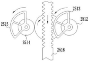
- leveling
- pipeline
- tailings
- gold tailings
- Prior art date
- Legal status (The legal status is an assumption and is not a legal conclusion. Google has not performed a legal analysis and makes no representation as to the accuracy of the status listed.)
- Active
Links
Images





Classifications
-
- F—MECHANICAL ENGINEERING; LIGHTING; HEATING; WEAPONS; BLASTING
- F26—DRYING
- F26B—DRYING SOLID MATERIALS OR OBJECTS BY REMOVING LIQUID THEREFROM
- F26B1/00—Preliminary treatment of solid materials or objects to facilitate drying, e.g. mixing or backmixing the materials to be dried with predominantly dry solids
- F26B1/005—Preliminary treatment of solid materials or objects to facilitate drying, e.g. mixing or backmixing the materials to be dried with predominantly dry solids by means of disintegrating, e.g. crushing, shredding, milling the materials to be dried
-
- F—MECHANICAL ENGINEERING; LIGHTING; HEATING; WEAPONS; BLASTING
- F26—DRYING
- F26B—DRYING SOLID MATERIALS OR OBJECTS BY REMOVING LIQUID THEREFROM
- F26B17/00—Machines or apparatus for drying materials in loose, plastic, or fluidised form, e.g. granules, staple fibres, with progressive movement
- F26B17/10—Machines or apparatus for drying materials in loose, plastic, or fluidised form, e.g. granules, staple fibres, with progressive movement with movement performed by fluid currents, e.g. issuing from a nozzle, e.g. pneumatic, flash, vortex or entrainment dryers
- F26B17/101—Machines or apparatus for drying materials in loose, plastic, or fluidised form, e.g. granules, staple fibres, with progressive movement with movement performed by fluid currents, e.g. issuing from a nozzle, e.g. pneumatic, flash, vortex or entrainment dryers the drying enclosure having the shape of one or a plurality of shafts or ducts, e.g. with substantially straight and vertical axis
- F26B17/105—Machines or apparatus for drying materials in loose, plastic, or fluidised form, e.g. granules, staple fibres, with progressive movement with movement performed by fluid currents, e.g. issuing from a nozzle, e.g. pneumatic, flash, vortex or entrainment dryers the drying enclosure having the shape of one or a plurality of shafts or ducts, e.g. with substantially straight and vertical axis the shaft or duct, e.g. its axis, being other than straight, i.e. curved, zig-zag, closed-loop, spiral
-
- F—MECHANICAL ENGINEERING; LIGHTING; HEATING; WEAPONS; BLASTING
- F26—DRYING
- F26B—DRYING SOLID MATERIALS OR OBJECTS BY REMOVING LIQUID THEREFROM
- F26B21/00—Arrangements for supplying or controlling air or other gases for drying solid materials or objects
- F26B21/001—Air generating units, e.g. movable or independent of drying enclosure
-
- F—MECHANICAL ENGINEERING; LIGHTING; HEATING; WEAPONS; BLASTING
- F26—DRYING
- F26B—DRYING SOLID MATERIALS OR OBJECTS BY REMOVING LIQUID THEREFROM
- F26B25/00—Details of general application not covered by group F26B21/00 or F26B23/00
- F26B25/001—Handling, e.g. loading or unloading arrangements
-
- F—MECHANICAL ENGINEERING; LIGHTING; HEATING; WEAPONS; BLASTING
- F26—DRYING
- F26B—DRYING SOLID MATERIALS OR OBJECTS BY REMOVING LIQUID THEREFROM
- F26B25/00—Details of general application not covered by group F26B21/00 or F26B23/00
- F26B25/005—Treatment of dryer exhaust gases
- F26B25/007—Dust filtering; Exhaust dust filters
-
- F—MECHANICAL ENGINEERING; LIGHTING; HEATING; WEAPONS; BLASTING
- F26—DRYING
- F26B—DRYING SOLID MATERIALS OR OBJECTS BY REMOVING LIQUID THEREFROM
- F26B3/00—Drying solid materials or objects by processes involving the application of heat
- F26B3/02—Drying solid materials or objects by processes involving the application of heat by convection, i.e. heat being conveyed from a heat source to the materials or objects to be dried by a gas or vapour, e.g. air
- F26B3/10—Drying solid materials or objects by processes involving the application of heat by convection, i.e. heat being conveyed from a heat source to the materials or objects to be dried by a gas or vapour, e.g. air the gas or vapour carrying the materials or objects to be dried with it
Landscapes
- Engineering & Computer Science (AREA)
- Mechanical Engineering (AREA)
- General Engineering & Computer Science (AREA)
- Life Sciences & Earth Sciences (AREA)
- Microbiology (AREA)
- Manufacture And Refinement Of Metals (AREA)
Abstract
The invention provides a device for preparing dried sand from gold tailings, which comprises a drying pipeline, wherein the drying pipeline is provided with a feed inlet, an air inlet, a pipeline waste outlet and a pipeline outlet; the feeding device is communicated with the feeding hole; the heating device is communicated with the air inlet; a separation device connected to the conduit outlet; the dust removal device is connected with the separation device; and the air supply and induction system is used for providing stable and continuous air volume for the drying pipeline, the heating device, the separating device and the dust removal device. By adopting the device and the using method thereof, the drying efficiency of the gold tailings can be improved by 2-3 times compared with the existing common drying system, the tailings treatment capacity is 70 tons/hour, and the device has the advantages of simple structure, few parts, large treatment capacity, high drying efficiency, low failure rate, high automation degree, simplicity in installation, low investment cost and the like, is used for rapidly drying other mining industry, tailings or large-particle materials, and has wide market prospect and remarkable economic and social benefits.
Description
Technical Field
The invention relates to the technical field of comprehensive utilization of gold tailings, in particular to a device for preparing dried sand from gold tailings and a using method thereof.
Background
As the number, scale and yield of gold mines in China are increasing day by day, the amount of tailings is also increased dramatically. According to incomplete statistics, the current stockpiling amount of gold tailings in China is 3 hundred million tons, and the stockpiling amount is continuously increased at a speed of 2450 million tons per year. Most of the gold tailings cannot be recycled and accumulated in a tailing pond, so that not only is a large amount of land occupied and atmosphere polluted, surface water and underground water occupied, but also the tailing pond is used for an overdue period or an overload period, even is operated illegally, and the tailing pond is greatly potential safety hazard. At present, the comprehensive utilization rate of metal tailings in China is less than 10% on average, and the comprehensive utilization rate is greatly lagged behind that of other bulk solid wastes. From the perspective of environmental protection, the gold tailings must be treated to avoid secondary pollution; from the aspect of resource protection, the gold tailings are utilized to change waste into valuable, turn harm into benefit, and relieve the outstanding contradiction between economic development, ecological environment destruction and resource shortage in China. Therefore, the treatment and the comprehensive utilization of the tailing slag of the tailings are accelerated.
The method for preparing the dried sand from the gold tailings for building materials, mine backfilling, river channel or underground filling and the like is one of the main ways for comprehensively utilizing the gold tailings at present. The drying process and device based on a roller drying system are generally adopted for preparing the drying sand from the gold tailings at present, the main body of the device is a slightly inclined rotary drum, a drum riding wheel device and a rotary driving device, a plurality of material raising plates with complex structures are distributed on the inner wall of the whole drum, when the drum rotates for one circle, the materials are picked up and sprinkled for the next time, the advancing distance of the materials is equal to the falling height multiplied by the inclination rate of the drum, so that the drying efficiency is low in the drying application of the gold tailings, the drying speed is about 30 tons/hour, and the drying system based on the drum dryer has more parts and high equipment failure rate, for example, the rolling ring swings and the drum vibrates relative to the operation of the drum body, so that the condition of stopping production of the equipment sometimes occurs, the maintenance cost of the equipment is high, therefore, the requirements of enterprises for efficiently treating the gold tailings in large batch and improving the economic benefit are difficult to meet.
Disclosure of Invention
The invention aims to provide a device for drying gold tailings into dry sand and a using method thereof, which have the advantages of high drying efficiency, large daily treatment capacity and low equipment maintenance cost, are more suitable for gold tailings treatment and solve the problems in the background technology.
In order to achieve the purpose, the invention adopts the technical scheme that:
the device for preparing the gold tailings into the dried sand is characterized by comprising a drying pipeline, wherein the drying pipeline is provided with a feeding hole, an air inlet and a pipeline outlet; the feeding device is communicated with the feeding hole; the heating device is communicated with the air inlet; a separation device connected to the conduit outlet; the dust removal device is connected with the separation device; and the air supply and induction system is used for providing stable and continuous air volume for the drying pipeline, the heating device, the separating device and the dust removal device.
Further, the drying pipeline is also provided with a pipeline waste outlet.
Furthermore, the drying pipeline is mainly formed by splicing a plurality of composite pipelines, and the composite pipelines are provided with a metal layer, a wear-resistant material layer and a ceramic layer from outside to inside.
Further, the feeding device comprises a belt feeding device, a tailing feeding control device is arranged above the belt feeding device, and the tailing feeding control device is arranged at a blanking end of the belt feeding device; the belt feeding device comprises a conveying belt.
Further, the tailing feeding control device comprises a mounting seat fixedly mounted on the feeding device, a motor seat arranged on the mounting seat, a motor fixedly mounted on the motor seat and a driving gear connected to an output shaft of the motor; the driving gear is meshed and connected with a rotary-flat driving wheel), the rotary-flat driving wheel is meshed and connected with a rotary-flat driving wheel, the rotary-flat driving wheel is meshed and connected with a rotary-flat driven wheel, and rotary-flat blades are fixedly mounted on the rotary-flat driving wheel and the rotary-flat driven wheel respectively;
the driving gear is also meshed with a push-flat driving wheel a, the push-flat driving wheel a is meshed with a push-flat driving wheel b, the push-flat driving wheel b is fixedly connected with a push-flat driving wheel c through a central shaft, and the push-flat driving wheel c and the push-flat driving wheel b synchronously rotate; the first leveling driving wheel is fixedly connected with a first sector gear through a central shaft; the second flat pushing driving wheel is fixedly connected with a second sector gear through a central shaft; a rack is meshed and connected between the first sector gear and the second sector gear, the rack is arranged on the mounting seat in a sliding manner, and the rack is fixedly connected with a leveling rake; the first sector gear and the second sector gear are identical in size, shape, material and installation angle.
Further, a tailing storage device is fixedly mounted on the belt feeding device.
Further, the distance from the lowest end of the rotary leveling blade to the conveyor belt is greater than the distance from the lowest end of the leveling rake to the conveyor belt.
Furthermore, a shifting block is arranged on the tooth surface of one side, opposite to the rack, of the flat pushing transmission wheel c, and an arc-shaped guide groove a and an arc-shaped guide groove b which are matched with the shifting block are respectively arranged at two ends of the rack.
Further, the metal layer and the wear-resistant material layer are in interference fit.
A use method of a device for preparing gold tailings into drying sand comprises the following steps:
s01: electrifying the heating device for preheating, and switching on the separating device, the dust remover and the power supply of the air supply and induction system when the internal temperature of the heating device reaches a set temperature;
s02: opening the air inlet, and allowing high-temperature gas in the heating device to enter the drying pipeline under the action of the air supply and induction system to form high-temperature gas flow;
s03: the power supply of the feeding device is switched on, and the gold tailings enter the drying pipeline from the feeding device through the feeding hole;
s04: under the combined action of the air supply and induction system and hot air flow, large-size gold tailings, stones and the like which do not meet set conditions in the gold tailings entering the drying pipeline move downwards and are discharged through the pipeline waste outlet, the gold tailings meeting the conditions travel along with the high-temperature air flow in a mixed mode, move upwards along the drying pipeline until dried sand is formed by drying, and then enter the separation device together with dust through the pipeline outlet;
s05: the dust entering the separating device enters the dust removing device under the action of the separating device and the air supply and induction system; the dried sand entering the interior of the separation device is separated.
Compared with the prior art, the invention has the beneficial effects that:
1. the invention adopts the technical scheme that a drying pipeline is directly connected with a feeding device, a heating device and a separating device, and a blowing system is arranged, the feeding device continuously feeds materials, the drying efficiency is improved by 2-3 times compared with the current common drying system, the gold tailings treatment capacity reaches 70 tons/hour, the device has simple structure and few parts, does not need a rotary drum, a drum riding wheel device, a rotary driving device, a lifting blade with complex structure, a cooling device and the like, has the advantages of large treatment capacity, high drying efficiency, low failure rate, high automation degree, simple installation, low investment cost and the like, is also used for quickly drying other mining industry, tailings or large-particle materials, and has wide market prospect and remarkable economic and social benefits.
2. The invention adopts the technical scheme that a drying pipeline replaces a drying roller, the gold tailings and the heated natural air enter the drying pipeline at the same time and are fully mixed, the drying efficiency is ensured because the specific surface area of heat-mass exchange is large and the drying stroke, namely the length of the drying pipeline, is long enough, and the drying sand undergoes the processes of first heating and then cooling in the pipeline because the drying stroke is long, the temperature of the drying sand is not increased much when the drying sand is discharged, the influence of the temperature on the product is small, the cooling link of the product is omitted, and the equipment investment cost and the later maintenance cost are reduced.
3. Through adopting "stoving pipeline is formed by the concatenation of a plurality of compound pipelines, and compound pipeline includes by outer and the technical scheme of the metal level that sets up, wear-resistant material layer and ceramic layer" in, can realize the quick replacement after the ceramic layer wearing and tearing, and compound pipeline can relapse repetitious usage, long service life, easy operation, and need not to dismantle the whole replacements that remove of stoving pipeline during the stoving pipeline maintenance, only need tear down certain section trouble pipeline, reduced the manpower, the financial resources cost of equipment maintenance.
4. According to the technical scheme, the tailings feeding control device is arranged above the belt feeding device and adopts a mode of rotary horizontal pushing and subsequent horizontal pushing, so that when the conveying capacity of tailings is increased suddenly, the pushing rake can push excessive tailings into the tailings storage device, and the failure of the spiral feeder caused by excessive tailings is prevented; the technical scheme that the distance from the lowest end of the rotary leveling blade to the conveyor belt is greater than the distance from the lowest end of the leveling rake to the conveyor belt is adopted, and the tailings are leveled into two stages, so that the reaction force borne by each working component is reduced, the reliability of the parts is improved, and the service life of the parts is prolonged; the tailing feeding control device has the advantages of simple structure, full adoption of gear and rack transmission, large transmission torque, low manufacturing cost, impact resistance, long service life, stable work and high equipment reliability.
5. According to the invention, the shifting block, the arc-shaped guide groove a and the arc-shaped guide groove b which are matched with the shifting block are arranged, so that the trend that the rack continuously moves along the original movement direction under the action of inertia is hindered, the meshing impact force and the surface friction force when the first sector gear and the second sector gear are initially contacted with the rack are effectively reduced, the heat treatment requirements of parts are reduced under the same mechanical property, the service lives of the parts are prolonged, and the stable operation of equipment is guaranteed.
Drawings
FIG. 1 is a schematic view of the overall construction of the present invention;
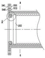
FIG. 2 is a partial cross-sectional view of a composite pipe of the present invention;
FIG. 3 is a schematic cross-sectional view taken along line B-B of FIG. 2;
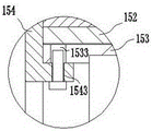
FIG. 4 is an enlarged view taken at A in FIG. 2;
FIG. 5 is a schematic structural diagram of a tailing feed control device;
FIG. 6 is a gear drive schematic of the spin-leveling device;
FIG. 7 is a schematic view of the relative positions of the rotating blades;
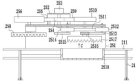
FIG. 8 is a schematic view of the portion of FIG. 5 taken along line C;
FIG. 9 is a schematic view of the first sector gear meshing with the rack;
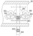
FIG. 10 is an enlarged view taken at D in FIG. 8;
in the figure, 10, a drying duct; 11. A feed inlet; 12. an air inlet; 13. a pipeline waste outlet; 14. a conduit outlet; 15. a composite conduit; 151. a metal layer; 1511. a metal layer via; 1512. a metal layer threaded hole; 152. a wear resistant material layer; 153. a ceramic layer; 1531. a protrusion; 1532. an annular groove; 1533. a ceramic layer through hole; 154. pressing a ring; 1541. a compression ring through hole; 1542. a press ring threaded hole; 1543. a threaded through hole; 20. a feeding device; 21. a belt feeding device; 211. a conveyor belt; 22. a hopper; 23. a screw feeder; 24. a motor; 25. a tailings feed control device; 251. a mounting seat; 252. a motor base; 253. a motor; 254. a driving gear; 255. rotating and leveling the driving wheel; 256. rotating and leveling the driving wheel; 257. rotating and leveling the driven wheel; 258. rotating and flattening the blades; 259. flattening the transmission wheel a; 2510. pushing the transmission wheel b flat; 2511. pushing the transmission wheel c flat; 25112. shifting blocks; 2512. a first leveling drive wheel; 2513. a first sector gear; 2514. a second leveling drive wheel; 2515. a second sector gear; 2516. a rack; 25161. an arc-shaped guide groove a; 25162. an arc-shaped guide groove b; 2517. a leveling harrow is pushed; 2518 a tailings storage device; 30. a heating device; 40. a blower; 50. a separation device; 51. a drying sand feed port; 52. an air outlet; 53. a discharge port; 60. drying the sand storage tank; 70. an air duct; 80. an induced draft fan; 90. a dust remover; 91. a dusty gas inlet; 92. an exhaust port; 100. a waste material storage tank.
Detailed Description
In order to make the technical means, objectives and functions of the present invention easy to understand, the present invention will be further described with reference to the following embodiments.
The device for preparing the dried sand from the gold tailings comprises a drying pipeline 10, wherein the drying pipeline 10 is provided with a feeding hole 11, an air inlet 12, a pipeline waste outlet 13 and a pipeline outlet 14; the feeding device 20 is communicated with the feeding hole 11; the heating device 30 is communicated with the air inlet 12; a separation device 50 connected to the conduit outlet 14; a dust removing device connected to the separating device 50; and the air supply and induction system is used for providing stable and continuous air volume for the drying pipeline 10, the heating device 30, the separating device 50 and the dust removal device.
Specifically, as shown in fig. 1, the device for preparing dried sand from gold tailings mainly comprises a drying pipeline 10, wherein the length and the diameter of the drying pipeline 10 are not limited, and can be selected according to the drying efficiency, the treatment capacity requirement and the moisture content of the dried sand, in this embodiment, the length of the drying pipeline 10 is 28 meters, and the diameter is 1 meter. The drying pipeline 10 is provided with a feed inlet 11, an air inlet 12, a pipeline waste outlet 13 and a pipeline outlet 14; the feeding hole 11 is positioned above the air inlet 12 and is connected with a feeding device 20 for continuously feeding materials to the drying pipeline 10; the air inlet 12 is connected with a heating device 30, the heating device 30 is connected with an air blower 40, and the heating device 30 continuously provides high-temperature and high-pressure gas for the drying pipeline 10 under the action of the air blower 40 for drying the gold tailings; the pipeline waste outlet 13 is arranged at the lower end of the drying pipeline 10, and a waste storage tank 100 is connected below the pipeline waste outlet 13 and used for storing large-particle sand blocks, stones and other waste materials; the pipeline outlet 14 is connected with a separating device 50 for separating the drying sand from the dust gas; the separation device 50 is provided with a dried sand feeding hole 51, an air outlet 52 and a discharge hole 53, the dried sand feeding hole 51 is connected with the pipeline outlet 14 in a matching way, the discharge hole 53 is positioned at the lower end of the separation device 50, a dried sand storage tank 60 is arranged below the discharge hole 53 and used for temporarily storing dried sand, and the dried sand storage tank 60 is connected with a conveying device and can convey the dried sand inside the dried sand storage tank to the next working procedure; the air outlet 52 is connected with an air pipe 70, the air pipe 70 is connected with an induced draft fan 80, the induced draft fan 80 is connected with a dust remover 90, and the dust remover 90 is provided with a dust-containing gas inlet 91 and an exhaust port 92.
Under the combined action of the air blower 40 and the induced draft fan 80, high-temperature air flow is formed in the drying pipeline 10, under the action of the high-temperature air flow, the high-temperature air flow enters the gold tailings in the drying pipeline 10 from the feeding hole 11, large-size gold tailings, stones and the like which do not meet set conditions move downwards and enter the waste storage tank 100 through the pipeline waste outlet 13, and the gold tailings which meet the conditions move upwards along the drying pipeline 10 until the gold tailings are dried and then enter the separation device 50 through the drying sand feeding hole 51; under the suction action of the separating device 50 and the induced draft fan 80, dust in the separating device 50 enters the dust remover 90 through the air pipe 70 and the dust-containing gas inlet 91 in sequence, gas purified by the dust remover 90 is discharged through the exhaust port 92, and the dust is blocked in the filter bag of the dust remover 90.
The feeding device 20 comprises a belt feeding device 21 and is used for conveying the gold tailings; the belt feeding device 21 is provided with a hopper 22 in a matching way and is used for temporarily storing the gold tailings conveyed by the belt feeding device 21; a screw feeder 23 is connected below the hopper 22, the screw feeder 23 is connected with a motor 24, and the screw feeder 23 continuously conveys the gold tailings in the hopper 22 to the drying pipeline 10 through the feeding port 11 under the driving of the motor 24.
As shown in fig. 2-4, the drying duct 10 is mainly formed by splicing a plurality of composite ducts 15, and the composite ducts are provided with a metal layer 151, a wear-resistant material layer 152 and a ceramic layer 153 from outside to inside; a plurality of metal layer through holes 1511 and metal layer threaded holes 1512 are formed in the metal layer 151; the metal layer 151 is in interference fit with the wear-resistant material layer 152, the wear-resistant material layer 152 is preferably an ultra-high molecular weight polyethylene pipe, and the ceramic layer 153 has the advantages of acid resistance, alkali resistance, chemical corrosion resistance, electrochemical corrosion resistance, high melting point, high hardness, high wear resistance, oxidation resistance and the like, so that the damage of ore sand to the inner wall due to collision is avoided, the wear resistance of the inner wall is improved, the equipment maintenance cost is reduced, and the service life of equipment is prolonged; the composite pipeline 15 further comprises a pressing ring 154, the cross section of one side of the pressing ring 154 is L-shaped, a plurality of pressing ring threaded holes 1542 matched with the metal layer threaded holes 1512 are formed in the pressing ring 154, and the pressing ring 154 and the metal layer 151 are screwed into the metal layer threaded holes 1512 and the pressing ring threaded holes 1542 through bolts to be connected and fixed; a plurality of pressing ring through holes 1541 matched with the metal layer through holes 1511 are formed in the pressing ring 154, and the adjacent composite pipes 15 are screwed into the metal layer through holes 1511 and the pressing ring through holes 1541 through bolts to be connected and fixed; the pressing ring 154 is further provided with a plurality of threaded through holes 1543 in the direction perpendicular to the axis on the pipe wall, a plurality of ceramic layer through holes 1533 matched with the threaded through holes 1543 of the pressing ring 154 are evenly distributed on the circumferences of the two ends of the ceramic layer 153, the pressing ring 154 and the ceramic layer 153 can be fixedly connected through bolts, the pressing ring 154 can be axially fixed on the ceramic layer 153, and the ceramic layer 153 is prevented from being displaced in the axial direction. The ultra-high molecular weight polyethylene pipe is an ultra-high molecular weight polyethylene pipe.
As shown in fig. 3, the ceramic layer 153 is provided with four protrusions 1531 and an annular groove 1532, the wear-resistant material layer 152 is provided with a guide groove matching with the protrusions 1531, the shape of the protrusions 1531 and the guide groove is not limited, here, the protrusions 1531 and the guide groove are preferably T-shaped and are matched in a clearance fit, the protrusions 1531 of the wear-resistant layer 153 can slide in the guide groove of the wear-resistant material layer 152, and the ceramic layer 153 is sleeved and fixed inside the wear-resistant material layer 152.
The failure of the screw feeder 23 is one of the main reasons causing the shutdown of the drying system of the invention, the tailings treated by the classifier are directly conveyed to the belt feeding device 21 by a belt for feeding, and the phenomenon of extrusion and blockage of the screw feeder 23 is easily caused in the actual production because the tailing feeding process after the treatment of the classifier cannot be ensured to be completely uniform. Because when the tailings fall in a uniform manner, the screw feeder 23 can stably convey the falling materials out. However, when the tailings suddenly increase and fall, the feed inlet of the screw feeder 23 is easily blocked due to the large particles, or when the tailings fall into the screw blades of the screw feeder 23, the sharply increased tailings are squeezed between the screw blades and the trough shell, so that the screw blades are stuck, and even a serious person can burn out the motor.
In order to ensure the uniform continuous feeding of the screw feeder 23, the tailing feeding control device 25 is arranged above the belt feeding device 21 of the present invention, the belt feeding device 21 includes a conveyor belt 211, as shown in fig. 5 and 6, the tailing feeding control device 25 is arranged at the blanking end of the conveyor belt 211 and includes a mounting seat 251 fixedly mounted on the feeding device 20, a motor seat 252 arranged on the mounting seat 251, a motor 253 fixedly mounted on the motor seat 252, and a driving gear 254 connected to an output shaft of the motor 253; the driving gear 254 is engaged with a plurality of rotating and leveling drive wheels, specifically, a rotating and leveling drive wheel 255 is provided in the present embodiment, the rotating and leveling drive wheel 255 is engaged with a rotating and leveling drive wheel 256, the rotating and leveling drive wheel 256 is engaged with a rotating and leveling driven wheel 257, the rotating and leveling drive wheel 256 and the rotating and leveling driven wheel 257 are respectively and fixedly provided with rotating and leveling blades 258, and four blades are installed on the rotating and leveling blades 258 in the present embodiment; when the motor 253 is started, the driving gear 254 is driven to rotate, so that the leveling driving wheel 255 is driven to rotate, the leveling driving wheel 255 rotates to drive the leveling driving wheel 256, the leveling driving wheel 256 drives the leveling driven wheel 257 to rotate, and the leveling blades 258 rotate under the rotation driving of the leveling driving wheel 256 and the leveling driven wheel 257, so that tailings accumulated on the center line of the driving belt 211 are unscrewed, and the pressure is reduced for the next tailing leveling step.
The driving gear 254 is further engaged with a plurality of leveling transmission wheels, specifically three in this embodiment, namely a leveling transmission wheel a259, a leveling transmission wheel b2510 engaged with the leveling transmission wheel a259, a leveling transmission wheel c2511 fixedly connected with the leveling transmission wheel b2510 through a central shaft, and the leveling transmission wheel c2511 and the leveling transmission wheel b2510 rotate synchronously. A first leveling driving wheel 2512 and a second leveling driving wheel 2514 which are completely the same in shape and size are meshed and connected with the leveling driving wheel c2511, and the first leveling driving wheel 2512 is fixedly connected with a first sector gear 2513 through a central shaft; the second leveling drive wheel 2514 is fixedly connected with a second sector gear 2515 through a central shaft; a rack 2516 is engaged and connected between the first sector gear 2513 and the second sector gear 2515, the rack 2516 is slidably arranged on the mounting seat 251, and a leveling rake 2517 is fixedly connected to the rack 2516. A tailings storage device 2518 is also fixedly mounted on the belt feeding device 21 and is used for temporarily storing the excess tailings conveyed.
The distance from the lowest end of the leveling blade 258 to the conveyor belt 211 is greater than the distance from the lowest end of the leveling rake 2517 to the conveyor belt 211, and the arrangement is to divide the leveling of the tailings into two stages, so that the reaction force borne by each working part is reduced, the reliability of the parts is improved, and the service life of the parts is prolonged; the blades of the leveling blade 258 and the leveling rake 2517 are provided with notches.
As shown in fig. 8 and 9, the first sector gear 2513 and the second sector gear 2515 have the same size, shape, material and installation angle, so that the first sector gear 2513 and the second sector gear 2515 rotate synchronously, and the sector angle of the first sector gear 2513 and the second sector gear 2515 is less than 170 °, so as to prevent the two parts from being engaged with the rack 2516 at the same time, wherein the specific angle is determined according to the moving distance of the leveling rake 2517.
As shown in fig. 10, a shifting block 25112 is provided on the tooth surface of the push-flat transmission wheel c2511 on the side opposite to the rack 2516, and an arc-shaped guide groove a25161 and an arc-shaped guide groove b25162 which are matched with the shifting block 25112 are respectively provided at both ends of the rack 2516.
When the motor 253 is started, the driving gear 254 is driven to rotate, so as to drive the leveling transmission wheel a259 and the leveling transmission wheel b2510 to rotate, the leveling transmission wheel b2510 rotates to synchronously drive the leveling transmission wheel c2511 to rotate, so as to drive the first leveling driving wheel 2512 and the second leveling driving wheel 2514 to synchronously rotate, the first leveling driving wheel 2512 and the second leveling driving wheel 2514 rotate to respectively drive the first sector gear 2513 and the second sector gear 2515 to synchronously rotate, when the first sector gear 2513 rotates to a position just separated from the rack 2516, the second sector gear 2515 starts to be in contact with the rack 2516, when the second sector gear 2515 rotates to a position just separated from the rack 2516, the first sector gear 2513 starts to be in contact with the rack 2516, and through the alternate meshing transmission of the first sector gear 2513 and the second sector gear 2515 and the rack 2516, so as to drive the rack 2516 to reciprocate along the direction perpendicular to the tailing conveying direction, the leveling rake 2517 can move back and forth along the direction perpendicular to the conveying direction of the conveyor belt 211 to level the tailings, and the leveled tailings then fall into the spiral feeder 23 through the hopper 22. If the tailings conveying amount is increased suddenly, the leveling rake 2517 can push the excessive tailings into the tailings storage device 2518, so that the failure of the screw feeder 23 caused by the excessive tailings is prevented.
As shown in fig. 8, when the first sector gear 2513 rotates to a position just separated from the rack 2516 and the second sector gear 2515 just contacts with the rack 2516, the shifting block 25112 rotates to the inside of the arc-shaped guide groove a25161, the rack 2516 stops its tendency of continuing to move downwards under the action of inertia and starts to move upwards under the driving of the shifting block 25112, and then the rack 2516 contacts with the second sector gear 2515 and moves upwards under the driving of the second sector gear 2515 and the shifting block 25112, and then the shifting block 25112 is screwed out of the inside of the arc-shaped guide groove a25161 and continues to rotate along with the push-flat driving wheel c 2511; similarly, when the second sector gear 2515 rotates to just separate from the rack 2516, the shifting block 25112 rotates to the inside of the arc-shaped guide slot b25162, and drives the rack 2516 to move upwards.
The setting of shifting block 25112 and the arc guide way a25161 and the arc guide way b25162 who matches with it has hindered rack 2516 and has continued the trend that moves along former direction of motion under the inertial action, has effectively slowed down meshing impact force and the surperficial frictional force when first sector gear 2513 and second sector gear 2515 and rack 2516 initial contact, under equal mechanical properties, has reduced the heat treatment requirement of spare part, has prolonged the life of spare part, provides the guarantee for the steady operation of equipment.
As shown in fig. 7, the working width of the two rotary blades 258 on the conveyor belt 211 is b1, the flattening width of the tailings on the conveyor belt 211 is b2 (i.e., the width after flattening when excessive conveying is not performed), and the working width and the maximum running conveying width of the flattening rake 2517 on the conveyor belt 211 are both b3, in this embodiment, b1< b2< b3< b4, when the conveyed tailings suddenly increase beyond the set conveying amount range b3, the flattening rake 2517 will push the excessive tailings into the tailings storage device 2518, so as to prevent the screw feeder 23 from failing due to the excessive tailings.
Because the tailings processed by the classifier are stacked in the middle of the conveyor belt 211 and have few parts on two sides when being discharged to the conveyor belt 211, the tailings are fed at a high speed and are conveyed in a large amount, and only a translational pushing mode is adopted, the reaction force borne by a pushing plate in the pushing process is large, and the requirements on the strength of equipment parts, motors and the like are high. The tailing feeding control device 25 adopts a mode of rotary pushing and subsequent translational pushing, has a simple structure, is completely transmitted by a gear and a rack, and has the advantages of large transmission torque, low manufacturing cost, impact resistance, long service life, stable work and high equipment reliability.
At present, drying systems of gold tailings and other tailings, coal, metallurgy and other industries are widely applied to a drum dryer as drying equipment, materials are discharged from a discharge port to a finished product conveyor through preheating, drying, cooling, dust removing and other areas to meet drying requirements at one time, the main body of the drying system is a slightly inclined rotary drum, a drum riding wheel device and a rotary driving device, a plurality of lifting blades with complex structures are distributed on the inner wall of the whole drum, when the drum rotates for one circle, the materials are lifted and sprayed for one time, the advancing distance of the materials is equal to the falling height of the materials multiplied by the inclination rate of the drum, the drying efficiency is low, the drying speed of the drying system which commonly adopts a three-drum dryer at present is about 30 tons/hour, the drying efficiency in the gold tailings drying application is low, and the number of parts of the drying system based on the drum dryer is large, the equipment fault rate is high, and if the relative barrel operation of rolling ring appears swing phenomenon, cylinder vibration etc. and the condition that leads to equipment to stop production sometimes takes place, is difficult to satisfy the requirement that the enterprise handles the gold tailing in batches on a large scale, improves economic benefits.
The invention adopts a pipeline type quick drying system, the gold tailings are conveyed by the screw feeder 23 and then enter the drying pipeline 10 together with the heated natural air, the gold tailings and the heated natural air are fully mixed, the drying efficiency is ensured because the heat-mass exchange specific surface area is large and the drying stroke, namely the length of the drying pipeline 10, is long enough, and the drying sand undergoes the processes of first temperature rise and then temperature drop in the pipeline because the drying stroke is long, the temperature of the drying sand is not increased much when the drying sand is discharged, the influence of the temperature on the product is small, and the temperature drop link is saved.
The working principle of the device for preparing the gold tailings into the drying sand is as follows: firstly, the heating device 30 is electrified for preheating, when the internal temperature of the heating device reaches the set temperature, the set temperature is 900-950 degrees in the embodiment, and the power supply of the separation device 50, the dust remover 90 and the induced draft fan 80 is switched on; then opening the air inlet 12, switching on the power supply of the blower 40, and allowing the high-temperature gas in the heating device 30 to enter the drying pipeline 10 under the action of the blower 40 and the induced draft fan 80 to form high-temperature gas flow; then the power supply of the screw feeder 23 and the belt feeding device 21 is switched on in sequence.
The belt feeding device 21 conveys the gold tailings to the hopper 22, the screw feeder 23 is connected below the hopper 22, and the gold tailings in the hopper 22 enter the drying pipeline 10 through the feeding hole 11 by the screw feeder 23. Under the combined action of the air blower 40, the induced draft fan 80 and the hot air flow, large-size gold tailings, stones and the like which do not meet set conditions in the gold tailings entering the drying pipeline 10 move downwards to enter the waste storage tank 100 through the pipeline waste outlet 13, the gold tailings meeting the conditions travel with the high-temperature air flow in a mixed mode, move upwards along the drying pipeline 10 until dried sand is formed, and then enter the separation device 50 together with dust through the dry sand feed inlet 51. Under the suction action of the separation device 50 and the induced draft fan 80, the dust entering the separation device 50 enters the dust remover 90 through the air pipe 70 and the dust-containing gas inlet 91 in sequence, the gas purified by the dust remover 90 is discharged through the exhaust port 92, and the dust is blocked in the filter bag of the dust remover 90; the dried sand entering the interior of the separation device 50 is separated and enters the dried sand storage tank 60 through the discharge port 53.
The device adopts an air flow drying method, the feeding device 20 continuously feeds materials, the drying efficiency is improved by 2-3 times compared with the current common drying system, the current device for manufacturing the gold tailings into dry sand by adopting the 28-meter drying pipeline 10 has the tailings treatment capacity of 70 tons/hour, has simple structure and few parts, does not need a rotary drum, a drum riding wheel device, a rotary driving device, a lifting blade with a complex structure, a cooling device and the like, has the advantages of large treatment capacity, high drying efficiency, low failure rate, high automation degree, simple installation, low investment cost and the like, has wide market prospect and remarkable economic and social benefits, and is developed successfully and enters an industrial application stage at present. The device for preparing the gold tailings into the dry sand and the use method thereof are also suitable for quickly drying other mining industries, tailings or large-particle materials.
The words of front, back, left, right, up and down, etc. in the present invention are only for convenience of describing the structure and do not form a limitation on the technical solution. The foregoing shows and describes the general principles and broad features of the present invention and advantages thereof. It will be understood by those skilled in the art that the present invention is not limited to the embodiments described above, which are described in the specification and illustrated only to illustrate the principle of the present invention, but that various changes and modifications may be made therein without departing from the spirit and scope of the present invention, which fall within the scope of the invention as claimed. The scope of the invention is defined by the appended claims and equivalents thereof.
Claims (8)
1. The device for preparing the gold tailings into the dried sand is characterized by comprising a drying pipeline (10), wherein the drying pipeline (10) is provided with a feeding hole (11), an air inlet (12) and a pipeline outlet (14); the feeding device (20) is communicated with the feeding hole (11); the heating device (30) is communicated with the air inlet (12); -a separation device (50) connected to the conduit outlet (14); a dust removal device connected to the separation device (50); the air supply and induction system is used for providing stable and continuous air volume for the drying pipeline (10), the heating device (30), the separating device (50) and the dust removal device;
the feeding device (20) comprises a belt feeding device (21), a tailing feeding control device (25) is arranged above the belt feeding device (21), and the tailing feeding control device (25) is arranged at a blanking end of the belt feeding device (21); the belt feeding device (21) comprises a conveyor belt (211);
the tailing feeding control device (25) comprises a mounting seat (251) fixedly mounted on the feeding device (20), a motor base (252) arranged on the mounting seat (251), a motor (253) fixedly mounted on the motor base (252), and a driving gear (254) connected to an output shaft of the motor (253); the driving gear (254) is meshed and connected with a spin-leveling driving wheel (255), the spin-leveling driving wheel (255) is meshed and connected with a spin-leveling driving wheel (256), the spin-leveling driving wheel (256) is meshed and connected with a spin-leveling driven wheel (257), and spin-leveling blades (258) are fixedly mounted on the spin-leveling driving wheel (256) and the spin-leveling driven wheel (257) respectively;
the driving gear (254) is further connected with a push-flat transmission wheel a (259) in a meshed mode, the push-flat transmission wheel a (259) is connected with a push-flat transmission wheel b (2510) in a meshed mode, the push-flat transmission wheel b (2510) is fixedly connected with a push-flat transmission wheel c (2511) through a central shaft, and the push-flat transmission wheel c (2511) and the push-flat transmission wheel b (2510) rotate synchronously; the push-flat transmission wheel c (2511) is connected with a first push-flat driving wheel (2512) and a second push-flat driving wheel (2514) in a meshed manner, and the first push-flat driving wheel (2512) is fixedly connected with a first sector gear (2513) through a central shaft; the second leveling driving wheel (2514) is fixedly connected with a second sector gear (2515) through a central shaft; a rack (2516) is connected between the first sector gear (2513) and the second sector gear (2515) in a meshed manner, the rack (2516) is arranged on the mounting seat (251) in a sliding manner, and a leveling rake (2517) is fixedly connected to the rack (2516); the first and second sector gears (2513, 2515) are identical in size, shape, material and mounting angle.
2. An apparatus for drying sand from gold tailings as claimed in claim 1, wherein the drying duct (10) is further provided with a duct waste outlet (13).
3. The device for drying sand from gold tailings according to claim 1 or 2, wherein the drying pipeline (10) is formed by splicing a plurality of composite pipelines (15), and the composite pipelines (15) are provided with a metal layer (151), a wear-resistant material layer (152) and a ceramic layer (153) from outside to inside.
4. The apparatus for drying sand from gold tailings as claimed in claim 1, wherein the distance from the lowest end of the leveling blade (258) to the conveyor belt (211) is greater than the distance from the lowest end of the leveling rake (2517) to the conveyor belt (211).
5. The device for making gold tailings into drying sand according to claim 4, wherein a tailings storage device (2518) is further fixedly mounted on the belt feeding device (21).
6. The device for drying sand from gold tailings according to claim 4, wherein a shifting block (25112) is arranged on the tooth surface of the side, opposite to the rack (2516), of the pushing and leveling transmission wheel c (2511), and an arc-shaped guide groove a (25161) and an arc-shaped guide groove b (25162) which are matched with the shifting block (25112) are respectively arranged at two ends of the rack (2516).
7. The apparatus for drying sand from gold tailings as claimed in claim 3, wherein the metal layer (151) is in interference fit with the wear-resistant material layer (152).
8. The use method of the device for preparing the gold tailings into the drying sand according to claim 2 is characterized by comprising the following steps:
s01: electrifying the heating device (30) for preheating, and switching on the separating device (50), the dust removing device and the power supply of the air supply and induction system when the internal temperature of the heating device (30) reaches a set temperature;
s02: the air inlet (12) is opened, and high-temperature gas in the heating device (30) enters the drying pipeline (10) under the action of the air supply and induction system to form high-temperature gas flow;
s03: the power supply of the feeding device (20) is switched on, and the gold tailings enter the drying pipeline (10) from the feeding device (20) through the feeding hole (11);
s04: under the combined action of the air supply and induction system and hot air flow, large-size gold tailings and stones which do not meet set conditions in the gold tailings entering the drying pipeline (10) move downwards and are discharged through the pipeline waste outlet (13), the gold tailings meeting the conditions travel with high-temperature air flow in a mixing manner, move upwards along the drying pipeline (10) until dried sand is formed by drying, and then the dried sand and dust enter the separation device (50) through the pipeline outlet (14);
s05: the dust entering the separating device (50) enters the dust removing device under the action of the separating device (50) and the air supply and induction system; the dried sand entering the interior of the separating device (50) is separated.
Priority Applications (1)
| Application Number | Priority Date | Filing Date | Title |
|---|---|---|---|
| CN201910959191.7A CN110595156B (en) | 2019-10-10 | 2019-10-10 | Device for preparing dried sand from gold tailings and using method thereof |
Applications Claiming Priority (1)
| Application Number | Priority Date | Filing Date | Title |
|---|---|---|---|
| CN201910959191.7A CN110595156B (en) | 2019-10-10 | 2019-10-10 | Device for preparing dried sand from gold tailings and using method thereof |
Publications (2)
| Publication Number | Publication Date |
|---|---|
| CN110595156A CN110595156A (en) | 2019-12-20 |
| CN110595156B true CN110595156B (en) | 2020-09-18 |
Family
ID=68866226
Family Applications (1)
| Application Number | Title | Priority Date | Filing Date |
|---|---|---|---|
| CN201910959191.7A Active CN110595156B (en) | 2019-10-10 | 2019-10-10 | Device for preparing dried sand from gold tailings and using method thereof |
Country Status (1)
| Country | Link |
|---|---|
| CN (1) | CN110595156B (en) |
Families Citing this family (3)
| Publication number | Priority date | Publication date | Assignee | Title |
|---|---|---|---|---|
| CN116412654A (en) * | 2021-12-31 | 2023-07-11 | 重庆有研重冶新材料有限公司 | A kind of drying method of non-ferrous metal powder |
| CN118463558B (en) * | 2024-05-31 | 2024-11-22 | 中核大地生态科技有限公司 | Tailings drying system based on remote data analysis and control |
| CN119436791A (en) * | 2024-11-21 | 2025-02-14 | 南通太洋高新材料科技有限公司 | A calcium fluoride raw material drying machine and method |
Family Cites Families (5)
| Publication number | Priority date | Publication date | Assignee | Title |
|---|---|---|---|---|
| CN102840750A (en) * | 2011-06-21 | 2012-12-26 | 沈琴 | Drying machine with dust removing device |
| CN203586731U (en) * | 2013-11-09 | 2014-05-07 | 上海金路成套设备有限公司 | Drying system for limestone powder |
| CN205619724U (en) * | 2016-04-28 | 2016-10-05 | 自贡市锋锐新材料有限公司 | Carborundum drying -machine |
| CN105835227B (en) * | 2016-05-26 | 2018-09-14 | 甘肃德龙生态建材有限公司 | A kind of production equipment of ecology dry-mixed mortar |
| CN208366030U (en) * | 2018-06-30 | 2019-01-11 | 唐山元瑞科技有限公司 | Ore in sand form drying equipment |
-
2019
- 2019-10-10 CN CN201910959191.7A patent/CN110595156B/en active Active
Also Published As
| Publication number | Publication date |
|---|---|
| CN110595156A (en) | 2019-12-20 |
Similar Documents
| Publication | Publication Date | Title |
|---|---|---|
| CN110595156A (en) | Device for preparing dried sand from gold tailings and using method thereof | |
| CN104826548A (en) | Combined-type granulating machine | |
| CN210718345U (en) | Device for making gold tailings into drying sand | |
| CN209333926U (en) | The feeding device of quartz sand crusher | |
| CN204769479U (en) | Sieve shaft type screening machine | |
| CN218706813U (en) | Sectional type wear-resistant material guide chute for iron and steel sintered mineral aggregate abrasive | |
| CN113976320A (en) | A kind of micropowder preselection equipment | |
| CN114183998A (en) | Steam rotation all-in-one machine and method for drying high-humidity and high-viscosity materials | |
| CN111617872A (en) | Large-scale dry-method enrichment ore dressing energy-saving and environment-friendly process for quartz-vein noble metal ore | |
| CN203209120U (en) | Energy-saving sand grinding machine | |
| CN209078921U (en) | A kind of domestic waste incineration residue regenerated aggregate brick making system | |
| CN112007719A (en) | Shaft mill | |
| CN2871456Y (en) | Blanking-material system set of petrol coke transferring station | |
| CN204642888U (en) | Unpowered automatic control chute anti-block apparatus | |
| CN211734148U (en) | Electronic sludge threading machine coupling low-temperature drying treatment system | |
| CN214811543U (en) | Fuel ore screening and dewatering device of fine casting powder production line | |
| CN202953533U (en) | Buffering discharging device | |
| CN202645589U (en) | Wet-type concrete injection machine | |
| CN206935501U (en) | A kind of large-scale overflow ball mill novel barrel liner plate | |
| CN108298213A (en) | A kind of coal bunker | |
| CN116899721B (en) | Continuous ball mill for high-fine grinding | |
| CN217165762U (en) | Broken line of steel scrap | |
| CN217410974U (en) | Material leakage preventing device for helical blade of feeding part of ball mill | |
| CN104354321A (en) | Ball press machine | |
| CN223457456U (en) | A transfer warehouse for transferring sticky materials |
Legal Events
| Date | Code | Title | Description |
|---|---|---|---|
| PB01 | Publication | ||
| PB01 | Publication | ||
| SE01 | Entry into force of request for substantive examination | ||
| SE01 | Entry into force of request for substantive examination | ||
| GR01 | Patent grant | ||
| GR01 | Patent grant |