Ditch debris clearance filter equipment for irrigation and water conservancy project
Technical Field
The invention relates to the technical field of hydraulic engineering equipment, in particular to a water channel sundry cleaning and filtering device for farmland hydraulic engineering.
Background
Need utilize the ditch to carry out certain water conservancy diversion to rivers when carrying out farmland irrigation, and the water of water conservancy diversion can contain certain debris usually, and long-time the piling up of debris can cause the ditch flow to diminish or even block up, consequently need clear up the debris of aquatic, and artifical handheld tool of tradition is long consuming time, the cost resource is great, the clearance effect is relatively poor to the ditch clearance, awaits improving urgently.
Disclosure of Invention
Aiming at the defects and shortcomings of the prior art, the invention provides the water channel sundries cleaning and filtering device for the farmland hydraulic engineering, which has the advantages of simple structure, reasonable design and convenient use, adopts a full-automatic cleaning process, reduces the investment of human resources, greatly improves the cleaning efficiency, adopts a continuous and uninterrupted cleaning mode, and ensures more thorough cleaning and stronger practicability.
In order to achieve the purpose, the invention adopts the technical scheme that: a channel sundry cleaning and filtering device for farmland hydraulic engineering comprises a bottom plate, a rack, an electric cabinet, a fishing device and a collecting device; the upper fixing frame of the ditch is provided with a bottom plate, the upper part of the right side of the bottom plate is vertically and fixedly provided with a rack, and the bottom of the rack is fixedly provided with an electric cabinet; the upper part of the bottom plate on the left side of the rack is fixedly provided with a collecting device, and the upper part of the water channel on the left side of the bottom plate is fixedly provided with a fishing device;
the fishing device comprises a fixed seat, a rotating shaft, a sleeve, a fixed plate and a fishing net; the front side and the rear side of the water channel are fixedly provided with fixed seats, a rotating shaft is rotatably arranged between the fixed seats through a bearing, and the rotating shaft is erected above the water channel; the rear end of the rotating shaft penetrates through the fixed seat and then extends to the rear side of the fixed seat, the extending end is connected with a first motor, and the first motor is fixedly arranged on the rear side wall of the fixed seat through a motor support; the first motor is connected with a power supply in the electric cabinet; a sleeve is fixedly sleeved in the middle of the rotating shaft, a plurality of fixing plates are fixedly arranged on the outer side wall of the sleeve in an equiangular manner, through holes are fixedly formed in the end parts of the fixing plates, and a fishing net is fixedly arranged on one side of each through hole; the bottom edge of the fixed plate at the lower side of the sleeve extends to the inner bottom of the ditch.
Furthermore, the collecting device comprises a collecting box, a slide rail, a first door frame, a scraping plate, a sewage intercepting plate, a second motor, an eccentric shaft, an adjusting column, a kidney-shaped groove and a slide block; the upper part of the left side of the bottom plate is fixedly provided with a collecting box, the collecting box is of a hollow structure with an opening at the upper part, sliding rails are symmetrically and fixedly arranged on the front side and the rear side of the upper part of the collecting box, the upper part of each sliding rail is provided with a sliding block in a sliding manner, and the upper part of each sliding block is fixedly provided with a sewage; the middle part of the collecting box is vertically and fixedly provided with a first portal frame, and the bottom of the first portal frame is fixedly arranged on the top surfaces of the collecting boxes on the front side and the rear side of the slide rail; a scraping plate is fixedly and obliquely arranged on the left side wall of the first portal frame, and the bottom side surface of the scraping plate is in contact with the upper surface of the sewage intercepting plate; two kidney-shaped grooves are symmetrically and fixedly arranged on the front side and the rear side of the right side wall of the sewage interception plate; the upper portion of frame is fixed and is provided with No. two motors, and No. two motors are connected with the power in the electric cabinet, and the output of No. two motors and the one end fixed connection of eccentric shaft, the other end vertical fixation of eccentric shaft are provided with the regulation post, and the front end activity of adjusting the post is worn to establish in the inside of two kidney slots.
Furthermore, the movement tangential direction of the lower edge of the fixed plate at the lower side of the sleeve is opposite to the water flow direction in the water channel; when the fishing net is arranged at the water bottom, the movement direction of the sundries in the water is just opposite to the fishing direction of the fishing net, and the fishing net cuts off the sundries and fishes the sundries out.
Furthermore, the height of the inner bottom surface of the collecting box is gradually increased from left to right, and a plurality of draining holes are fixedly formed in the bottom of the left side wall of the collecting box; after the sundries are salvaged, the sundries are scraped and conveyed into the collecting box through the scraper, moisture is mixed with the sundries, and the height difference of the bottom in the collecting box discharges the moisture to the inside of the water channel from the draining hole.
Furthermore, a supporting plate is vertically and fixedly arranged on one side of the fixing plate, which is provided with the fishing net, and one side surface of the supporting plate is fixedly connected with the fishing net; the supporting plate supports the shape of the fishing net, and the supporting plate is prevented from turning to the other surface of the fixing plate along with sundries in the process of dumping the sundries.
Furthermore, two guardrails are vertically and symmetrically fixedly arranged on the front side and the rear side of the sewage intercepting plate; when intercepting the debris that the dirty board was emptyd, the guardrail is effectual has prevented that debris from intercepting both sides landing around the dirty board.
Furthermore, a second door frame is vertically and fixedly arranged on the collecting box on the right side of the first door frame, the sewage intercepting plate movably penetrates through the middle part of the second door frame, an elastic steel sheet is fixedly arranged on the inner top surface of the second door frame, and the bottom of the elastic steel sheet is abutted against the upper surface of the sewage intercepting plate; the elastic steel sheet scrapes the residual sewage on the sewage intercepting plate, so that the sewage is prevented from corroding the surface of the sewage intercepting plate.
After adopting the structure, the invention has the beneficial effects that:
1. the first motor drives the rotating shaft to rotate, so that the fixing plate makes circular motion around the rotating shaft, the fishing net takes out sundries in water, and the cleaning process is full-automatic, so that the investment of human resources is reduced, and the cleaning efficiency is greatly improved;
2. a motor drives the incessant salvage of scoop net, and No. two motors pass through the mechanical interlock effect of eccentric shaft, regulation post and kidney slot for cut dirty board constantly and do the round trip movement of left right direction between the fixed plate, continuous, incessant clearance mode, make the debris of fishing out obtain in time clearing up, clear up more thoroughly, and the practicality is stronger.
Drawings
The invention is further described below with reference to the accompanying drawings:
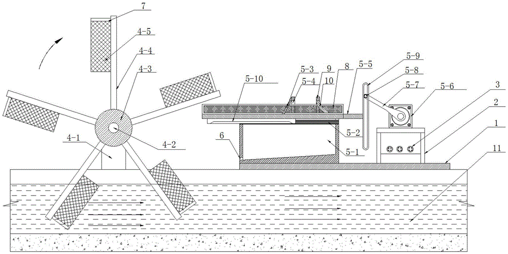
FIG. 1 is a schematic structural view of a device for cleaning and filtering sundries in a water channel for the irrigation and water conservancy project.
Fig. 2 is a top view of fig. 1.
Fig. 3 is a structural view illustrating the sewage interception plate 5-5 moved to the right side.
Fig. 4 is a schematic view of the connection structure of the kidney-shaped groove, the eccentric shaft and the adjustment column of the present invention.
Fig. 5 is a schematic view of the connection structure of the first gantry and the scraper.
Description of reference numerals:
the device comprises a bottom plate 1, a rack 2, an electric cabinet 3, a fishing device 4, a fixing seat 4-1, a rotating shaft 4-2, a sleeve 4-3, a fixing plate 4-4, a fishing net 4-5, a first motor 4-6, a collecting device 5, a collecting box 5-1, a sliding rail 5-2, a first door frame 5-3, a scraping plate 5-4, a sewage intercepting plate 5-5, a second motor 5-6, an eccentric shaft 5-7, an adjusting column 5-8, a kidney-shaped groove 5-9, a sliding block 5-10, a draining hole 6, a supporting plate 7, a guardrail 8, a second door frame 9, an elastic steel sheet 10 and a water channel 11.
Detailed Description
The invention will be further described with reference to the accompanying drawings.
As shown in fig. 1-5, the invention discloses a channel sundry cleaning and filtering device for the irrigation and water conservancy project, which comprises: the fishing device comprises a bottom plate 1, a rack 2, an electric cabinet 3, a fishing device 4 and a collecting device 5; the upper fixing frame of the ditch 11 is provided with a bottom plate 1, the bottom plate 1 adopts a prefabricated cement board, the upper part of the right side of the bottom plate 1 is vertically and fixedly provided with a rack 2 through bolts, the bottom of the rack 2 is fixedly provided with an electric cabinet 3, and a power supply and a KS02Y controller are arranged in the electric cabinet 3 so as to control the sequence of the operation of the electric elements in the device; a collecting device 5 is fixedly arranged on the upper part of a bottom plate 1 on the left side of the rack 2, and a fishing device 4 is arranged on a fixed frame on the upper part of a water channel 11 on the left side of the bottom plate 1;
the fishing device 4 comprises a fixed seat 4-1, a rotating shaft 4-2, a sleeve 4-3, a fixed plate 4-4 and a fishing net 4-5; the front side and the rear side of the water channel 11 are fixedly provided with fixed seats 4-1 through bolts, a rotating shaft 4-2 is rotatably arranged between the fixed seats 4-1 through a bearing, and the rotating shaft 4-2 is erected above the water channel 11; the rear end of the rotating shaft 4-2 penetrates through the fixed seat 4-1 and then extends to the rear side of the fixed seat 4-1, the extending end is connected with a first motor 4-6, the first motor 4-6 adopts a 60KTYZ speed reducing motor, and the first motor 4-6 is fixedly arranged on the rear side wall of the fixed seat 4-1 through a motor bracket and a bolt; the first motor 4-6 is connected with a power supply and a controller in the electric cabinet 3; the middle part of the rotating shaft 4-2 is fixedly welded and sleeved with a sleeve 4-3, the outer side wall of the sleeve 4-3 is fixedly provided with five fixing plates 4-4 in an equiangular shape, the end parts of the fixing plates 4-4 are fixedly provided with through holes, and one sides of the through holes are fixedly provided with fishing nets 4-5 through bolts; the bottom edge of the fixing plate 4-4 at the lower side of the sleeve 4-3 extends to the inner bottom of the ditch 11, and sundries enter the interior of the fishing net 4-5 through the through hole;
the collecting device 5 comprises a collecting box 5-1, a slide rail 5-2, a first door frame 5-3, a scraping plate 5-4, a sewage interception plate 5-5, a second motor 5-6, an eccentric shaft 5-7, an adjusting column 5-8, a kidney-shaped groove 5-9 and a sliding block 5-10; the upper part of the left side of the bottom plate 1 is fixedly provided with a collecting box 5-1 through bolts, the collecting box 5-1 is of a hollow structure with an opening at the upper part, the front side and the rear side of the upper part of the collecting box 5-1 are symmetrically and fixedly provided with slide rails 5-2 through bolts, the upper part of the slide rail 5-2 is provided with a slide block 5-10 in a sliding manner, the slide block 5-10 adopts a long-strip-shaped slide block 5-10, and the upper part of the slide block 5-10 is fixedly provided with a sewage; the middle part of the collecting box 5-1 is vertically and fixedly welded with a first portal 5-3, and the bottom of the first portal 5-3 is fixedly welded on the top surfaces of the collecting box 5-1 at the front side and the rear side of the slide rail 5-2; a scraping plate 5-4 is fixedly and obliquely arranged on the left side wall of the first portal 5-3, the bottom side surface of the scraping plate 5-4 is in contact with the upper surface of the dirt intercepting plate 5-5, and sundries on the dirt intercepting plate 5-5 are scraped by the scraping plate 5-4; two kidney-shaped grooves 5-9 are symmetrically and fixedly welded on the front side and the rear side of the right side wall of the sewage interception plate 5-5; the upper part of the frame 2 is fixedly provided with a second motor 5-6 through bolts and a motor bracket, the second motor 5-6 adopts a PANASONIC 5A servo motor, the second motor 5-6 is connected with a power supply and a controller in the electric cabinet 3, the output end of the second motor 5-6 is fixedly connected with one end of an eccentric shaft 5-7, the other end of the eccentric shaft 5-7 is vertically and fixedly welded with an adjusting column 5-8, the front end of the adjusting column 5-8 is movably arranged inside two kidney-shaped grooves 5-9, and the length of the kidney-shaped grooves 5-9 is twice that of the eccentric shaft 5-7.
Furthermore, the movement tangential direction of the lower edge of the fixing plate 4-4 at the lower side of the sleeve 4-3 is opposite to the water flow direction in the water channel 11; when the fishing net 4-5 is positioned at the water bottom, the movement direction of the sundries in the water is just opposite to the fishing direction of the fishing net 4-5, the fishing net 4-5 cuts off the sundries and fishes out the sundries, and the sundries can not be fished out along the water flow direction.
Furthermore, the height of the bottom surface in the collection box 5-1 is gradually increased from left to right, and a plurality of draining holes 6 are fixedly arranged at the bottom of the left side wall of the collection box 5-1; after the sundries are fished, the sundries are scraped and conveyed into the collecting box 5-1 through the scraper 5-4, moisture is mixed in the sundries, the height difference of the bottom in the collecting box 5-1 is arranged to discharge the moisture into the ditch 11 from the draining hole 6, the box body is prevented from being corroded by sewage, and the service life of the device is prolonged.
Furthermore, a supporting plate 7 is vertically and fixedly welded on one side of the fixing plate 4-4, which is provided with the fishing net 4-5, and one side surface of the supporting plate 7 is fixedly connected with the fishing net 4-5 through a bolt; the shape of the fishing net 4-5 is supported by the supporting plate 7, so that the fishing net 4-5 is prevented from turning to the other side of the fixing plate 4-4 along with sundries in the process of dumping the sundries, and the shape of the fishing net 4-5 is fixed.
Furthermore, two guardrails 8 are vertically and symmetrically fixedly arranged on the front side and the rear side of the sewage intercepting plate 5-5 through bolts; when the trash blocking plate 5-5 blocks the dumped sundries, the guardrail 8 effectively prevents the sundries from sliding off from the front side and the rear side of the trash blocking plate 5-5.
Furthermore, a second door frame 9 is vertically and fixedly welded on the collecting box 5-1 on the right side of the first door frame 5-3, the sewage intercepting plate 5-5 movably penetrates through the middle part of the second door frame 9, an elastic steel sheet 10 is fixedly welded on the inner top surface of the second door frame 9, and the bottom of the elastic steel sheet 10 is abutted against the upper surface of the sewage intercepting plate 5-5; the elastic steel sheet 10 scrapes off the residual sewage on the sewage interception plate 5-5, so that the sewage is prevented from corroding the surface of the sewage interception plate 5-5.
The working principle of the specific embodiment is as follows: according to the usual water delivery direction of the ditch 11, the installation direction of the whole device is determined; the first motor 4-6 and the second motor 5-6 are connected with a power supply in the electric cabinet 3, the output end of the first motor 4-6 drives the rotating shaft 4-2 to rotate, so that the sleeve 4-3 drives the fixed plate 4-4 to do circular motion around the axis of the rotating shaft 4-2, when the fishing net 4-5 at the end part of the fixed plate 4-4 moves below the water surface, the fishing net 4-5 salvages the sundries in the water in the interior of the fishing net 4-5 due to the fact that water flow flows in the reverse direction, and the sundries rotate along with the fixed plate 4-4 in the fishing net 4-5; when the fishing net 4-5 with sundries moves to the right side of the vertical line at the upper part of the sleeve 4-3, the output end of the second motor 5-6 drives the eccentric shaft 5-7 to rotate, because the adjusting column 5-8 is inserted in the kidney-shaped groove 5-9, the adjusting column 5-8 moves up and down in the kidney-shaped groove 5-9 in the process of the rotation of the eccentric shaft 5-7, when the eccentric shaft 5-7 rotates to the left side of the second motor 5-6 and the axis of the eccentric shaft 5-7 is in the horizontal position, at this time, the kidney-shaped groove 5-9 pushes the sewage interception plate 5-5 to move on the slide rail 5-2 to the left side of the collection box 5-1, the sewage interception plate 5-5 is just positioned between the fixed plate 4-4 with sundries and the adjacent lower fixed plate 4-4, the sundries fall to the upper part of the sewage interception plate 5-5 under the action of gravity, similarly, the second motor 5-6 drives the eccentric shaft 5-7 to rotate, the kidney-shaped groove 5-9 pushes the sewage interception plate 5-5 to move rightwards, the scraper 5-4 pushes the sundries on the sewage interception plate 5-5 to the inside of the collection box 5-1 at the lower side of the sewage interception plate 5-5, and the sundries are filtered.
Finally, it should be noted that: although the present invention has been described in detail with reference to the foregoing embodiments, it will be apparent to those skilled in the art that changes may be made in the embodiments and/or equivalents thereof without departing from the spirit and scope of the invention. Any modification, equivalent replacement, or improvement made within the spirit and principle of the present invention should be included in the protection scope of the present invention.