CN110523526B - A metal powder recovery device in the process of stainless steel processing - Google Patents
A metal powder recovery device in the process of stainless steel processing Download PDFInfo
- Publication number
- CN110523526B CN110523526B CN201910702001.3A CN201910702001A CN110523526B CN 110523526 B CN110523526 B CN 110523526B CN 201910702001 A CN201910702001 A CN 201910702001A CN 110523526 B CN110523526 B CN 110523526B
- Authority
- CN
- China
- Prior art keywords
- box
- metal powder
- fixedly installed
- installation
- stainless steel
- Prior art date
- Legal status (The legal status is an assumption and is not a legal conclusion. Google has not performed a legal analysis and makes no representation as to the accuracy of the status listed.)
- Expired - Fee Related
Links
Images


Classifications
-
- B—PERFORMING OPERATIONS; TRANSPORTING
- B03—SEPARATION OF SOLID MATERIALS USING LIQUIDS OR USING PNEUMATIC TABLES OR JIGS; MAGNETIC OR ELECTROSTATIC SEPARATION OF SOLID MATERIALS FROM SOLID MATERIALS OR FLUIDS; SEPARATION BY HIGH-VOLTAGE ELECTRIC FIELDS
- B03C—MAGNETIC OR ELECTROSTATIC SEPARATION OF SOLID MATERIALS FROM SOLID MATERIALS OR FLUIDS; SEPARATION BY HIGH-VOLTAGE ELECTRIC FIELDS
- B03C1/00—Magnetic separation
- B03C1/02—Magnetic separation acting directly on the substance being separated
-
- B—PERFORMING OPERATIONS; TRANSPORTING
- B21—MECHANICAL METAL-WORKING WITHOUT ESSENTIALLY REMOVING MATERIAL; PUNCHING METAL
- B21D—WORKING OR PROCESSING OF SHEET METAL OR METAL TUBES, RODS OR PROFILES WITHOUT ESSENTIALLY REMOVING MATERIAL; PUNCHING METAL
- B21D37/00—Tools as parts of machines covered by this subclass
-
- B—PERFORMING OPERATIONS; TRANSPORTING
- B23—MACHINE TOOLS; METAL-WORKING NOT OTHERWISE PROVIDED FOR
- B23Q—DETAILS, COMPONENTS, OR ACCESSORIES FOR MACHINE TOOLS, e.g. ARRANGEMENTS FOR COPYING OR CONTROLLING; MACHINE TOOLS IN GENERAL CHARACTERISED BY THE CONSTRUCTION OF PARTICULAR DETAILS OR COMPONENTS; COMBINATIONS OR ASSOCIATIONS OF METAL-WORKING MACHINES, NOT DIRECTED TO A PARTICULAR RESULT
- B23Q11/00—Accessories fitted to machine tools for keeping tools or parts of the machine in good working condition or for cooling work; Safety devices specially combined with or arranged in, or specially adapted for use in connection with, machine tools
Landscapes
- Engineering & Computer Science (AREA)
- Mechanical Engineering (AREA)
- Combined Means For Separation Of Solids (AREA)
Abstract
本发明公开了一种不锈钢加工过程中金属粉末回收装置,包括筛料箱和对称固定安装在筛料箱两端的两个安装箱,筛料箱的顶壁上固定插设有进料管,进料管的顶端固定安装有进料斗,筛料箱和两个安装箱内共同可活动安装有安装框,安装框一端的外侧壁上固定安装有安装块。本发明中将混入杂质的金属粉末经进料斗倒入筛料箱内,金属粉末受电磁铁磁力吸引后均被吸附在电磁铁上,杂质由于自身重力原因会落入筛料箱底端的废料收集箱内,吸附有金属粉末的电磁铁移动至安装箱内后由于断电会使得吸附在电磁铁上的杂质自动落入安装箱底端的金属粉末收集箱内,不仅操作方便,而且分离效果好,改善了金属粉末的回收效果。
The invention discloses a metal powder recovery device in the process of stainless steel processing, which comprises a screening material box and two installation boxes which are symmetrically and fixedly installed at both ends of the screening material box. A feeding pipe is fixedly inserted on the top wall of the screening material box. A feeding hopper is fixedly installed on the top of the material pipe, an installation frame is movably installed in the screening material box and the two installation boxes, and an installation block is fixedly installed on the outer side wall of one end of the installation frame. In the present invention, the metal powder mixed with impurities is poured into the sieve box through the feeding hopper. After the metal powder is attracted by the electromagnet, it is adsorbed on the electromagnet, and the impurities will fall into the waste collection at the bottom of the sieve box due to its own gravity. In the box, after the electromagnet adsorbed with metal powder is moved into the installation box, the impurities adsorbed on the electromagnet will automatically fall into the metal powder collection box at the bottom of the installation box due to the power failure, which is not only easy to operate, but also has a good separation effect. The recovery effect of metal powder is improved.
Description
技术领域technical field
本发明涉及金属粉末回收装置技术领域,尤其涉及一种不锈钢加工过程中金属粉末回收装置。The invention relates to the technical field of metal powder recovery devices, in particular to a metal powder recovery device during stainless steel processing.
背景技术Background technique
不锈钢加工工艺是指凭着不锈钢的性能对不锈钢进行剪、折、弯、焊等机械加工最终得到工业生产所需的不锈钢制品的过程,在不锈钢加工的过程中需要借助大量的机床、仪器、不锈钢加工设备,在这个过程中产生了大量的金属粉末,金属粉末回收装置是利用金属比杂质质量大的原理,进行风力区分,目前的金属粉末回收装置不能进行分类,金属粉末中含有的大量杂质,针对上述问题,在原有不锈钢加工过程中金属粉末回收装置的基础上进行创新设计。Stainless steel processing technology refers to the process of cutting, folding, bending, welding and other mechanical processing of stainless steel based on the properties of stainless steel to finally obtain stainless steel products required for industrial production. Processing equipment, a large amount of metal powder is produced in this process. The metal powder recovery device uses the principle that the metal is larger than the impurities to distinguish by wind. The current metal powder recovery device cannot be classified, and the metal powder contains a large amount of impurities. In view of the above problems, an innovative design is carried out on the basis of the original metal powder recovery device in the process of stainless steel processing.
经检索,中国专利号CN208427211U公开了一种不锈钢加工过程中金属粉末回收装置,包括传送带、磁铁棒、分离仓和冷加工装置,所述传送带的侧面安装有支撑板,所述传送带的两侧安装有挡板,所述磁铁棒安装在传送带的内侧,所述分离仓安装在传送带的下方,所述冷加工装置的下方设置有磁铁,所述传送带的下方安装有刮板。After searching, Chinese Patent No. CN208427211U discloses a metal powder recovery device in the process of stainless steel processing, including a conveyor belt, a magnet bar, a separation bin and a cold processing device. baffle, the magnet bar is installed on the inner side of the conveyor belt, the separation bin is installed under the conveyor belt, a magnet is installed under the cold working device, and a scraper is installed under the conveyor belt.
现有的不锈钢加工过程中金属粉末回收装置存在以下不足之处:结构复杂,由于金属粉末和杂质的质量均较小,因此使用电扇按重量对金属粉末和杂质进行区分的效果较差,不仅操作麻烦,而且金属粉末回收效果较差。In the existing stainless steel processing process, the metal powder recovery device has the following shortcomings: the structure is complex, and since the quality of the metal powder and impurities are both small, the effect of using an electric fan to distinguish the metal powder and impurities by weight is poor, not only the operation It is troublesome, and the recovery effect of metal powder is poor.
发明内容SUMMARY OF THE INVENTION
本发明的目的是为了解决现有技术中金属粉末从杂质中分离效果较差导致金属粉末回收效果差的问题,而提出的一种不锈钢加工过程中金属粉末回收装置。The purpose of the present invention is to solve the problem of poor metal powder recovery effect caused by poor separation effect of metal powder from impurities in the prior art, and proposes a metal powder recovery device during stainless steel processing.
为了实现上述目的,本发明采用了如下技术方案:In order to achieve the above object, the present invention adopts the following technical solutions:
一种不锈钢加工过程中金属粉末回收装置,包括筛料箱和对称固定安装在筛料箱两端的两个安装箱,所述筛料箱的顶壁上固定插设有进料管,所述进料管的顶端固定安装有进料斗,所述筛料箱和两个安装箱内共同可活动安装有安装框,所述安装框一端的外侧壁上固定安装有安装块,且安装块远离安装框的一端延伸至筛料箱和安装箱的外侧,两个所述安装箱相对一端的外侧壁上均固定安装有固定块,两个所述固定块上共同可转动安装有丝杆,所述丝杆贯穿安装块设置,且丝杆与安装块相互螺纹啮合,所述丝杆上连接有驱动装置,所述安装框上均匀固定安装有多个电磁铁,所述电磁铁远离安装块的一端均固定连接有电源,所述电源分别固定安装在对应的电磁铁上,且电源远离电磁铁的一端均延伸至筛料箱和安装箱的外侧,每个所述电源远离电磁铁的一端均安装有控制按钮,每个所述控制按钮远离电源的一端均固定安装有与控制按钮相互配合的控制块,且控制块分别可活动安装在对应的电源上,所述筛料箱和安装箱一侧的外侧壁上共同固定安装有密封框,且电源远离电磁铁的一端均位于密封框内,所述密封框靠近筛料箱一侧的内侧壁上固定安装有与控制块相互配合的控制板,所述筛料箱的底壁上固定安装有废料收集箱,两个所述安装箱内均设有卸料装置。A metal powder recovery device in the process of stainless steel processing, comprising a screen box and two installation boxes symmetrically and fixedly installed at both ends of the screen box, a feeding pipe is fixedly inserted on the top wall of the screen box, and the A feeding hopper is fixedly installed at the top of the material pipe, a mounting frame is movably installed in the screening box and the two installation boxes, and a mounting block is fixedly installed on the outer side wall of one end of the mounting frame, and the mounting block is far away from the installation. One end of the frame extends to the outside of the screening material box and the installation box, a fixing block is fixedly installed on the outer side walls of the opposite ends of the two installation boxes, and a screw rod is rotatably installed on the two fixing blocks. The screw rod is arranged through the mounting block, and the screw rod and the mounting block are threadedly engaged with each other, a driving device is connected to the screw rod, and a plurality of electromagnets are evenly fixed and installed on the mounting frame, and the electromagnet is away from one end of the mounting block. They are all fixedly connected with a power supply, the power supplies are fixedly installed on the corresponding electromagnets, and the end of the power supply away from the electromagnet extends to the outside of the screen box and the installation box, and each end of the power supply away from the electromagnet is installed. There are control buttons, each end of the control button away from the power supply is fixedly installed with a control block that cooperates with the control button, and the control block can be movably installed on the corresponding power supply, and the screen box and the installation box are on one side. A sealing frame is fixedly installed on the outer side wall of the screen, and the end of the power supply away from the electromagnet is located in the sealing frame. A waste collection box is fixedly installed on the bottom wall of the screening box, and a discharging device is provided in both of the installation boxes.
优选地,所述驱动装置包括伺服电机,所述伺服电机的输出端固定安装有转轴,所述转轴与丝杆之间连接有传动装置。Preferably, the driving device includes a servo motor, an output end of the servo motor is fixedly mounted with a rotating shaft, and a transmission device is connected between the rotating shaft and the screw rod.
优选地,所述传动装置包括分别固定安装在转轴和丝杆上的第一锥齿轮和第二锥齿轮,且第一锥齿轮和第二锥齿轮相互齿轮啮合。Preferably, the transmission device includes a first bevel gear and a second bevel gear fixedly mounted on the rotating shaft and the screw rod respectively, and the first bevel gear and the second bevel gear are geared to each other.
优选地,每个所述控制块靠近电源的一端均等距离固定安装有多个活动杆,且活动杆远离控制块的一端均插设在电源上,每个所述活动杆的外侧壁上均绕设有弹簧,且弹簧的两端分别固定安装在电源和控制块上。Preferably, a plurality of movable rods are fixedly installed at an equal distance from one end of each of the control blocks close to the power supply, and the end of the movable rods away from the control block is inserted into the power supply, and the outer side wall of each movable rod is wound around the power supply. A spring is provided, and the two ends of the spring are respectively fixed on the power supply and the control block.
优选地,所述控制块均为锥形块,且控制块均与控制板相互配合,所述控制板的长度与筛料箱的长度相等,且控制板与筛料箱的位置相对应。Preferably, the control blocks are all conical blocks, and the control blocks cooperate with a control plate, the length of the control plate is equal to that of the screen box, and the positions of the control plate and the screen box correspond.
优选地,所述卸料装置包括均匀固定安装在安装箱顶壁上的多个风扇,且风扇均与安装箱相互连通,两个所述安装箱的底壁上均固定安装有金属粉末收集箱。Preferably, the unloading device includes a plurality of fans uniformly and fixedly installed on the top wall of the installation box, and the fans are all communicated with the installation box, and metal powder collection boxes are fixedly installed on the bottom walls of the two installation boxes. .
与现有技术相比,本发明有如下有益效果:Compared with the prior art, the present invention has the following beneficial effects:
1、将混入杂质的金属粉末经进料斗倒入筛料箱内,金属粉末受电磁铁磁力吸引后均被吸附在电磁铁上,杂质由于自身重力原因会落入筛料箱底端的废料收集箱内,吸附有金属粉末的电磁铁移动至安装箱内后由于断电会使得吸附在电磁铁上的杂质自动落入安装箱底端的金属粉末收集箱内,不仅操作方便,而且分离效果好,改善了金属粉末的回收效果;1. Pour the metal powder mixed with impurities into the sieve box through the feeding hopper. After the metal powder is attracted by the electromagnet, it will be adsorbed on the electromagnet. The impurities will fall into the waste collection box at the bottom of the sieve box due to its own gravity. Inside, after the electromagnet adsorbed with metal powder is moved into the installation box, the impurities adsorbed on the electromagnet will automatically fall into the metal powder collection box at the bottom of the installation box due to the power failure, which is not only easy to operate, but also has a good separation effect. Recovery effect of metal powder;
2、结构简单,只需启动伺服电机就可以方便的对金属粉末进行回收,无需人工手动操作,不仅操作方便,而且回收效率高,实用效果好。2. The structure is simple, and the metal powder can be recovered conveniently just by starting the servo motor without manual operation. It is not only easy to operate, but also has high recovery efficiency and good practical effect.
附图说明Description of drawings
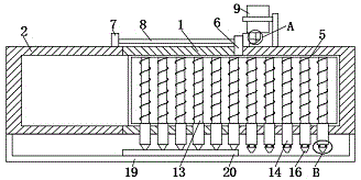
图1为本发明提出的一种不锈钢加工过程中金属粉末回收装置的顶端部分结构的剖视图;1 is a cross-sectional view of the top part structure of a metal powder recovery device in a stainless steel processing process proposed by the present invention;
图2为本发明提出的一种不锈钢加工过程中金属粉末回收装置的俯视图;2 is a top view of a metal powder recovery device in a stainless steel processing process proposed by the present invention;
图3为本发明提出的一种不锈钢加工过程中金属粉末回收装置的侧面结构示意图;Fig. 3 is a side structure schematic diagram of a metal powder recovery device in a stainless steel processing process proposed by the present invention;
图4为本发明提出的一种不锈钢加工过程中金属粉末回收装置的A部分结构的放大图;4 is an enlarged view of the structure of part A of the metal powder recovery device in a stainless steel processing process proposed by the present invention;
图5为本发明提出的一种不锈钢加工过程中金属粉末回收装置的B部分结构的放大图。FIG. 5 is an enlarged view of the structure of part B of a metal powder recovery device in a stainless steel processing process proposed by the present invention.
图中:1筛料箱、2安装箱、3进料管、4进料斗、5安装框、6安装块、7固定块、8丝杆、9伺服电机、10转轴、11第一锥齿轮、12第二锥齿轮、13电磁铁、14电源、15控制按钮、16控制块、17活动杆、18弹簧、19密封框、20控制板、21废料收集箱、22风扇、23金属粉末收集箱。In the picture: 1 screen box, 2 installation box, 3 feed pipe, 4 feed hopper, 5 installation frame, 6 installation block, 7 fixed block, 8 screw rod, 9 servo motor, 10 shaft, 11 first bevel gear , 12 second bevel gear, 13 electromagnet, 14 power supply, 15 control button, 16 control block, 17 movable rod, 18 spring, 19 sealing frame, 20 control board, 21 waste collection box, 22 fan, 23 metal powder collection box .
具体实施方式Detailed ways
下面将结合本发明实施例中的附图,对本发明实施例中的技术方案进行清楚、完整地描述,显然,所描述的实施例仅仅是本发明一部分实施例,而不是全部的实施例。The technical solutions in the embodiments of the present invention will be clearly and completely described below with reference to the accompanying drawings in the embodiments of the present invention. Obviously, the described embodiments are only a part of the embodiments of the present invention, but not all of the embodiments.
在本发明的描述中,需要理解的是,术语“上”、“下”、“前”、“后”、“左”、“右”、“顶”、“底”、“内”、“外”等指示的方位或位置关系为基于附图所示的方位或位置关系,仅是为了便于描述本发明和简化描述,而不是指示或暗示所指的装置或元件必须具有特定的方位、以特定的方位构造和操作,因此不能理解为对本发明的限制。In the description of the present invention, it should be understood that the terms "upper", "lower", "front", "rear", "left", "right", "top", "bottom", "inside", " The orientation or positional relationship indicated by "outside" is based on the orientation or positional relationship shown in the accompanying drawings, and is only for the convenience of describing the present invention and simplifying the description, rather than indicating or implying that the indicated device or element must have a specific orientation, so as to The specific orientation configuration and operation are therefore not to be construed as limitations of the present invention.
参照图1-5,一种不锈钢加工过程中金属粉末回收装置,包括筛料箱1和对称固定安装在筛料箱1两端的两个安装箱2,筛料箱1的顶壁上固定插设有进料管3,进料管3的顶端固定安装有进料斗4,筛料箱1和两个安装箱2内共同可活动安装有安装框5,安装框5一端的外侧壁上固定安装有安装块6,且安装块6远离安装框5的一端延伸至筛料箱1和安装箱2的外侧,两个安装箱2相对一端的外侧壁上均固定安装有固定块7,两个固定块7上共同可转动安装有丝杆8,丝杆8贯穿安装块6设置,且丝杆8与安装块6相互螺纹啮合,丝杆8上连接有驱动装置,驱动装置包括伺服电机9,伺服电机9的输出端固定安装有转轴10,转轴10与丝杆8之间连接有传动装置,传动装置包括分别固定安装在转轴10和丝杆8上的第一锥齿轮11和第二锥齿轮12,且第一锥齿轮11和第二锥齿轮12相互齿轮啮合,启动伺服电机9,伺服电机9驱动转轴10和第一锥齿轮11转动,第一锥齿轮11与第二锥齿轮12相互齿轮啮合,因此第一锥齿轮11转动可以带动第二锥齿轮12和丝杆8转动,丝杆8与安装块6相互螺纹啮合,因此丝杆8周期性转动可以带动安装块6和安装框5水平方向往复运动。1-5, a metal powder recovery device in the process of stainless steel processing, including a
安装框5上均匀固定安装有多个电磁铁13,电磁铁13远离安装块6的一端均固定连接有电源14,电源14分别固定安装在对应的电磁铁13上,且电源14远离电磁铁13的一端均延伸至筛料箱1和安装箱2的外侧,每个电源14远离电磁铁13的一端均安装有控制按钮15,每个控制按钮15远离电源14的一端均固定安装有与控制按钮15相互配合的控制块16,且控制块16分别可活动安装在对应的电源14上,每个控制块16靠近电源14的一端均等距离固定安装有多个活动杆17,且活动杆17远离控制块16的一端均插设在电源14上,每个活动杆17的外侧壁上均绕设有弹簧18,且弹簧18的两端分别固定安装在电源14和控制块16上,控制按钮15和控制块16均可活动安装在电源14上。A plurality of
筛料箱1和安装箱2一侧的外侧壁上共同固定安装有密封框19,且电源14远离电磁铁13的一端均位于密封框19内,密封框19靠近筛料箱1一侧的内侧壁上固定安装有与控制块16相互配合的控制板20,控制块16均为锥形块,且控制块16均与控制板20相互配合,控制板20的长度与筛料箱1的长度相等,且控制板20与筛料箱1的位置相对应,电磁铁13移动至筛料箱1内后,控制板20会挤压控制块16和控制按钮15并使电源14通电,从而可以将筛料箱1内的金属粉末吸附在电磁铁13上,吸附有金属粉末的电磁铁13移动至安装箱2内后,弹簧18由于恢复自身弹力会推动控制块16和控制按钮15移动至远离电源14的一端,从而使得电源14断电,由于断电会使得吸附在电磁铁13上的杂质自动掉落。A sealing
筛料箱1的底壁上固定安装有废料收集箱21,两个安装箱2内均设有卸料装置,卸料装置包括均匀固定安装在安装箱2顶壁上的多个风扇22,且风扇22均与安装箱2相互连通,两个安装箱2的底壁上均固定安装有金属粉末收集箱23,吸附有金属粉末的电磁铁13移动至安装箱2内后,弹簧18由于恢复自身弹力会推动控制块16和控制按钮15移动至远离电源14的一端,从而使得电源14断电,由于断电会使得吸附在电磁铁13上的杂质被风扇22吹入安装箱2底端的金属粉末收集箱23内,可以加速电磁铁13上的杂质落入底端的金属粉末收集箱23内。A
本发明中,启动伺服电机9,伺服电机9驱动转轴10和第一锥齿轮11转动,第一锥齿轮11与第二锥齿轮12相互齿轮啮合,因此第一锥齿轮11转动可以带动第二锥齿轮12和丝杆8转动,丝杆8与安装块6相互螺纹啮合,因此丝杆8周期性转动可以带动安装块6、安装框5和电磁铁13水平方向往复运动,将混入杂质的金属粉末经进料斗4和进料管3倒入筛料箱1内,金属粉末受电磁铁13磁力吸引后均被吸附在电磁铁13上,杂质由于自身重力原因会落入筛料箱1底端的废料收集箱21内,吸附有金属粉末的电磁铁13移动至安装箱2内后,弹簧18由于恢复自身弹力会推动控制块16和控制按钮15移动至远离电源14的一端,从而使得电源14断电,由于断电会使得吸附在电磁铁13上的杂质被风扇22吹入安装箱2底端的金属粉末收集箱23内,去除完金属粉末的电磁铁13移动至筛料箱1内后,控制板20会挤压控制块16和控制按钮15并使电源14通电,从而又可以将筛料箱1内的金属粉末吸附在电磁铁13上,如此循环就可以对混有杂质的金属粉末进行回收。In the present invention, the
进一步说明,上述固定连接,除非另有明确的规定和限定,否则应做广义理解,例如,可以是焊接,也可以是胶合,或者一体成型设置等本领域技术人员熟知的惯用手段。It is further stated that the above-mentioned fixed connection should be understood in a broad sense unless otherwise specified and limited. For example, it may be welding, gluing, or a conventional means known to those skilled in the art, such as integral molding.
需要说明的是,在本文中,诸如第一和第二等之类的关系术语仅仅用来将一个实体或者操作与另一个实体或操作区分开来,而不一定要求或者暗示这些实体或操作之间存在任何这种实际的关系或者顺序。而且,术语“包括”、“包含”或者其任何其他变体意在涵盖非排他性的包含,从而使得包括一系列要素的过程、方法、物品或者设备不仅包括那些要素,而且还包括没有明确列出的其他要素,或者是还包括为这种过程、方法、物品或者设备所固有的要素。It should be noted that, in this document, relational terms such as first and second are used only to distinguish one entity or operation from another entity or operation, and do not necessarily require or imply any relationship between these entities or operations. any such actual relationship or sequence exists. Moreover, the terms "comprising", "comprising" or any other variation thereof are intended to encompass non-exclusive inclusion such that a process, method, article or device comprising a list of elements includes not only those elements, but also includes not explicitly listed or other elements inherent to such a process, method, article or apparatus.
以上所述,仅为本发明较佳的具体实施方式,但本发明的保护范围并不局限于此,任何熟悉本技术领域的技术人员在本发明揭露的技术范围内,根据本发明的技术方案及其发明构思加以等同替换或改变,都应涵盖在本发明的保护范围之内。The above description is only a preferred embodiment of the present invention, but the protection scope of the present invention is not limited to this. The equivalent replacement or change of the inventive concept thereof shall be included within the protection scope of the present invention.
Claims (6)
Priority Applications (1)
| Application Number | Priority Date | Filing Date | Title |
|---|---|---|---|
| CN201910702001.3A CN110523526B (en) | 2019-07-31 | 2019-07-31 | A metal powder recovery device in the process of stainless steel processing |
Applications Claiming Priority (1)
| Application Number | Priority Date | Filing Date | Title |
|---|---|---|---|
| CN201910702001.3A CN110523526B (en) | 2019-07-31 | 2019-07-31 | A metal powder recovery device in the process of stainless steel processing |
Publications (2)
| Publication Number | Publication Date |
|---|---|
| CN110523526A CN110523526A (en) | 2019-12-03 |
| CN110523526B true CN110523526B (en) | 2020-08-04 |
Family
ID=68661198
Family Applications (1)
| Application Number | Title | Priority Date | Filing Date |
|---|---|---|---|
| CN201910702001.3A Expired - Fee Related CN110523526B (en) | 2019-07-31 | 2019-07-31 | A metal powder recovery device in the process of stainless steel processing |
Country Status (1)
| Country | Link |
|---|---|
| CN (1) | CN110523526B (en) |
Families Citing this family (6)
| Publication number | Priority date | Publication date | Assignee | Title |
|---|---|---|---|---|
| CN111056684B (en) * | 2019-12-31 | 2022-03-18 | 常州庆源机械科技有限公司 | Dielectric liquid filtering, separating and recycling device of spark erosion drilling machine |
| CN112121996A (en) * | 2020-09-23 | 2020-12-25 | 江苏威拉里新材料科技有限公司 | A magnetic suction metal powder separation device |
| CN113478643A (en) * | 2021-08-02 | 2021-10-08 | 吴继军 | Ceramic raw material pugging machine for domestic ceramic processing |
| CN113908979B (en) * | 2021-09-26 | 2024-11-22 | 山西锦绣盛亮工贸有限公司 | Dust adsorption type magnetic separation equipment for iron powder in steel slag |
| CN115672543A (en) * | 2022-11-18 | 2023-02-03 | 安徽中科春谷激光产业技术研究院有限公司 | Composite metal powder separation device for 3DP and use method thereof |
| CN118371438A (en) * | 2024-01-16 | 2024-07-23 | 衡阳市雅典娜石英石有限公司 | A quartz sand selection equipment combining air separation and magnetic separation |
Family Cites Families (9)
| Publication number | Priority date | Publication date | Assignee | Title |
|---|---|---|---|---|
| SU780891A1 (en) * | 1978-12-18 | 1980-11-23 | Кременчугский Завод Технического Углерода Им. 60-Летия Великой Октябрьской Социалистической Революции | Electromagnetic separator |
| KR101038868B1 (en) * | 2003-10-20 | 2011-06-02 | 주식회사 포스코 | Iron removal device in rolling oil of cold rolling process |
| CN102773158B (en) * | 2012-08-27 | 2014-12-03 | 淄博盛金稀土新材料科技有限公司 | Equipment for eliminating iron scraps from raw materials |
| KR20140057986A (en) * | 2012-11-05 | 2014-05-14 | 이주훈 | Magnetic fine powder removal device using magnets |
| CN203565190U (en) * | 2013-11-28 | 2014-04-30 | 苏增荣 | Double-bearing type deironing machine |
| CN207576647U (en) * | 2017-12-27 | 2018-07-06 | 安徽庐江县汉通建设工程有限责任公司 | A kind of building waste sorting equipment |
| CN108311199B (en) * | 2018-01-31 | 2020-04-07 | 重庆谦谦装饰工程有限公司 | Building rubbish metal separator |
| CN207930509U (en) * | 2018-02-23 | 2018-10-02 | 安庆工匠智能化设备制造有限公司 | A kind of scrap cleaning device |
| CN109395812B (en) * | 2018-09-17 | 2021-04-06 | 徽仁(宁夏)环保科技有限公司 | A construction waste crushing and iron removing device |
-
2019
- 2019-07-31 CN CN201910702001.3A patent/CN110523526B/en not_active Expired - Fee Related
Also Published As
| Publication number | Publication date |
|---|---|
| CN110523526A (en) | 2019-12-03 |
Similar Documents
| Publication | Publication Date | Title |
|---|---|---|
| CN110523526A (en) | A metal powder recovery device in stainless steel processing | |
| CN218794356U (en) | Waste recovery device for chemical production | |
| CN103488070A (en) | Recovery system and recovery method for selenium drum | |
| CN210436247U (en) | Sealing strip flattening and cutting machine with automatic cleaning function | |
| CN115338012A (en) | An environment-friendly NdFeB permanent magnet waste recovery device and method thereof | |
| CN116329069B (en) | Mineral aggregate screening conveying equipment | |
| CN213761996U (en) | Glass raw materials for production broken edulcoration device | |
| CN219899033U (en) | Vibrating screen for concentrating machine | |
| CN211756742U (en) | A dust removal device for vermicelli processing | |
| CN113878121A (en) | Metallurgical automatic cycle metal reducing mechanism | |
| CN205572787U (en) | Waste recycling device for insulating material production | |
| CN218840753U (en) | Powder material conveying device | |
| CN210187257U (en) | Novel based on for machine-building smash device | |
| CN112588361A (en) | Crushing device for recycling aluminum alloy waste | |
| CN108273593B (en) | A system for building processing | |
| CN115382654A (en) | Impact crushing and screening device for high-purity silicon production and processing | |
| CN212882937U (en) | Magnetic suction type impurity removal feeding hopper | |
| CN218108289U (en) | Automatic waste discharge sorting device of punch press | |
| CN211191085U (en) | Stamping plate surface iron fillings cleaning device | |
| CN116440994A (en) | Raw material crushing device for producing and processing modified plastics | |
| CN210753728U (en) | A high-efficiency, energy-saving and environmentally friendly screening production line | |
| CN211333716U (en) | Low energy consumption 3D printer pay-off structure | |
| CN210411497U (en) | White corundum screening plant | |
| CN218201136U (en) | Handheld automatic feeding mechanism | |
| CN218394666U (en) | Efficient rice sieve separator |
Legal Events
| Date | Code | Title | Description |
|---|---|---|---|
| PB01 | Publication | ||
| PB01 | Publication | ||
| SE01 | Entry into force of request for substantive examination | ||
| SE01 | Entry into force of request for substantive examination | ||
| TA01 | Transfer of patent application right |
Effective date of registration: 20200709 Address after: No.3, block D, Guanghua dacaozhai Industrial Zone, Xingtan town, Shunde District, Foshan City, Guangdong Province Applicant after: Foshan Shunde Degang metal heat treatment Co.,Ltd. Address before: 100089, Peking University, 5 the Summer Palace Road, Beijing, Haidian District Applicant before: Feng Cuili |
|
| TA01 | Transfer of patent application right | ||
| GR01 | Patent grant | ||
| GR01 | Patent grant | ||
| CF01 | Termination of patent right due to non-payment of annual fee |
Granted publication date: 20200804 |
|
| CF01 | Termination of patent right due to non-payment of annual fee |