CN110485363B - Simulation device and multi-point real-time monitoring method for dynamic change of river bed under flood - Google Patents
Simulation device and multi-point real-time monitoring method for dynamic change of river bed under flood Download PDFInfo
- Publication number
- CN110485363B CN110485363B CN201910820133.6A CN201910820133A CN110485363B CN 110485363 B CN110485363 B CN 110485363B CN 201910820133 A CN201910820133 A CN 201910820133A CN 110485363 B CN110485363 B CN 110485363B
- Authority
- CN
- China
- Prior art keywords
- laser
- flood
- sand layer
- simulation
- water
- Prior art date
- Legal status (The legal status is an assumption and is not a legal conclusion. Google has not performed a legal analysis and makes no representation as to the accuracy of the status listed.)
- Active
Links
- 238000004088 simulation Methods 0.000 title claims abstract description 62
- 238000000034 method Methods 0.000 title claims abstract description 18
- 238000012544 monitoring process Methods 0.000 title claims abstract description 10
- 230000008859 change Effects 0.000 title claims description 15
- XLYOFNOQVPJJNP-UHFFFAOYSA-N water Substances O XLYOFNOQVPJJNP-UHFFFAOYSA-N 0.000 claims abstract description 77
- 239000004576 sand Substances 0.000 claims abstract description 72
- 238000005259 measurement Methods 0.000 claims abstract description 33
- 230000009471 action Effects 0.000 claims abstract description 27
- 238000004364 calculation method Methods 0.000 claims abstract description 7
- 238000009736 wetting Methods 0.000 claims description 8
- 238000009434 installation Methods 0.000 claims description 6
- 230000008569 process Effects 0.000 claims description 6
- 230000005484 gravity Effects 0.000 claims description 4
- 239000011159 matrix material Substances 0.000 claims description 3
- 238000002360 preparation method Methods 0.000 claims description 3
- 238000011144 upstream manufacturing Methods 0.000 claims description 3
- 238000006424 Flood reaction Methods 0.000 abstract description 8
- 238000001514 detection method Methods 0.000 description 6
- 238000002474 experimental method Methods 0.000 description 5
- 238000009991 scouring Methods 0.000 description 4
- 238000012876 topography Methods 0.000 description 3
- 238000010586 diagram Methods 0.000 description 2
- 238000005265 energy consumption Methods 0.000 description 2
- 238000005516 engineering process Methods 0.000 description 2
- 230000003628 erosive effect Effects 0.000 description 2
- 239000002245 particle Substances 0.000 description 2
- 230000035515 penetration Effects 0.000 description 2
- 238000007796 conventional method Methods 0.000 description 1
- 238000009795 derivation Methods 0.000 description 1
- 238000013461 design Methods 0.000 description 1
- 239000012530 fluid Substances 0.000 description 1
- 238000003384 imaging method Methods 0.000 description 1
- 230000009191 jumping Effects 0.000 description 1
- 238000002844 melting Methods 0.000 description 1
- 230000008018 melting Effects 0.000 description 1
- 238000012986 modification Methods 0.000 description 1
- 230000004048 modification Effects 0.000 description 1
- 238000011160 research Methods 0.000 description 1
- 239000013535 sea water Substances 0.000 description 1
- 239000007787 solid Substances 0.000 description 1
- 239000000126 substance Substances 0.000 description 1
Images


Classifications
-
- E—FIXED CONSTRUCTIONS
- E02—HYDRAULIC ENGINEERING; FOUNDATIONS; SOIL SHIFTING
- E02B—HYDRAULIC ENGINEERING
- E02B1/00—Equipment or apparatus for, or methods of, general hydraulic engineering, e.g. protection of constructions against ice-strains
- E02B1/02—Hydraulic models
-
- G—PHYSICS
- G01—MEASURING; TESTING
- G01B—MEASURING LENGTH, THICKNESS OR SIMILAR LINEAR DIMENSIONS; MEASURING ANGLES; MEASURING AREAS; MEASURING IRREGULARITIES OF SURFACES OR CONTOURS
- G01B11/00—Measuring arrangements characterised by the use of optical techniques
- G01B11/02—Measuring arrangements characterised by the use of optical techniques for measuring length, width or thickness
- G01B11/06—Measuring arrangements characterised by the use of optical techniques for measuring length, width or thickness for measuring thickness ; e.g. of sheet material
- G01B11/0616—Measuring arrangements characterised by the use of optical techniques for measuring length, width or thickness for measuring thickness ; e.g. of sheet material of coating
- G01B11/0625—Measuring arrangements characterised by the use of optical techniques for measuring length, width or thickness for measuring thickness ; e.g. of sheet material of coating with measurement of absorption or reflection
-
- G—PHYSICS
- G01—MEASURING; TESTING
- G01B—MEASURING LENGTH, THICKNESS OR SIMILAR LINEAR DIMENSIONS; MEASURING ANGLES; MEASURING AREAS; MEASURING IRREGULARITIES OF SURFACES OR CONTOURS
- G01B11/00—Measuring arrangements characterised by the use of optical techniques
- G01B11/02—Measuring arrangements characterised by the use of optical techniques for measuring length, width or thickness
- G01B11/06—Measuring arrangements characterised by the use of optical techniques for measuring length, width or thickness for measuring thickness ; e.g. of sheet material
- G01B11/0616—Measuring arrangements characterised by the use of optical techniques for measuring length, width or thickness for measuring thickness ; e.g. of sheet material of coating
- G01B11/0683—Measuring arrangements characterised by the use of optical techniques for measuring length, width or thickness for measuring thickness ; e.g. of sheet material of coating measurement during deposition or removal of the layer
-
- G—PHYSICS
- G01—MEASURING; TESTING
- G01M—TESTING STATIC OR DYNAMIC BALANCE OF MACHINES OR STRUCTURES; TESTING OF STRUCTURES OR APPARATUS, NOT OTHERWISE PROVIDED FOR
- G01M10/00—Hydrodynamic testing; Arrangements in or on ship-testing tanks or water tunnels
Landscapes
- Physics & Mathematics (AREA)
- General Physics & Mathematics (AREA)
- Engineering & Computer Science (AREA)
- General Engineering & Computer Science (AREA)
- Fluid Mechanics (AREA)
- Mechanical Engineering (AREA)
- Civil Engineering (AREA)
- Structural Engineering (AREA)
- Length Measuring Devices By Optical Means (AREA)
Abstract
本发明公开了一种洪水作用下河床动态变化的模拟装置,包括河道模拟槽,槽内设有坝体,坝体上设有电动闸门;坝体上下游的河道模拟槽分别为蓄水区和洪水模拟区,洪水模拟区的底部铺设有砂层,砂层下方的河道模拟槽的底壁上安装有若干高频压力传感器;各高频压力传感器的正上方一一对应设有激光装置;电控装置根据砂层实时厚度计算公式计算出对应砂层的实时厚度。本发明还公开了使用上述洪水作用下河床动态变化的模拟装置进行的多点实时监测方法。本发明对水体及砂层均不造成干扰,且不要求水槽的边壁透明,可实现多点测量,在需要的监测点的河道模拟槽的底壁上安装高频压力传感器并对应设置激光装置,测量结果较为精确。
The invention discloses a simulation device for dynamic changes of a river bed under the action of floods, which comprises a river channel simulation tank, a dam body is arranged in the channel, and an electric gate is arranged on the dam body; In the flood simulation area, a sand layer is laid at the bottom of the flood simulation area, and a number of high-frequency pressure sensors are installed on the bottom wall of the channel simulation tank below the sand layer; a laser device is installed one-to-one corresponding to each high-frequency pressure sensor; The control device calculates the real-time thickness of the corresponding sand layer according to the calculation formula of the real-time thickness of the sand layer. The invention also discloses a multi-point real-time monitoring method using the simulation device for dynamic changes of the river bed under the action of flood. The invention does not interfere with the water body and the sand layer, and does not require the side wall of the water tank to be transparent, and can realize multi-point measurement. A high-frequency pressure sensor is installed on the bottom wall of the river channel simulation tank at the required monitoring point and a laser device is correspondingly arranged. , the measurement results are more accurate.
Description
技术领域technical field
本发明涉及水利工程技术领域,尤其涉及一种洪水作用下河床动态变化的模拟装置及多点实时监测方法。The invention relates to the technical field of hydraulic engineering, in particular to a simulation device and a multi-point real-time monitoring method for dynamic changes of a river bed under the action of floods.
背景技术Background technique
洪水是水利界术语,是指暴雨、急骤融冰化雪、风暴潮、溃坝等因素引起的江河湖海水量迅速增加或水位迅猛上涨的水流现象。洪水流速快,前端水头差大,对下游河床冲刷快速且剧烈,随之会引起各种地质灾害。因此,有必要对洪水作用下河床动态变化规律开展实验研究。但由于洪水具有汹涌湍急的特点,使得河床冲刷过程极为迅速、剧烈且难以实时、无干扰地进行监测。Flood is a term in the field of water conservancy, which refers to the phenomenon of rapid increase of sea water volume or rapid rise of water level in rivers and lakes caused by factors such as heavy rain, rapid melting of ice and snow, storm surge, and dam break. The flood flow is fast, and the front-end water head difference is large, and the scouring of the downstream riverbed is fast and violent, which will cause various geological disasters. Therefore, it is necessary to carry out experimental research on the dynamic change law of the riverbed under the action of flood. However, due to the turbulent characteristics of floods, the scouring process of the riverbed is extremely rapid and violent, and it is difficult to monitor in real time and without interference.
传统的对洪水作用下地形变化的测量多是在洪水流过且地形稳定以后,对最终的河床高程进行测量,常用的有探测锤、探测杆等,但是不能做到对行洪过程中的地形变化情况进行实时测量。The traditional measurement of terrain changes under the action of floods is mostly to measure the final river bed elevation after the flood flows and the terrain is stable. Commonly used detection hammers, detection rods, etc., but the terrain during the flood discharge process cannot be measured. Changes are measured in real time.
有研究者提出在河床中的固定深度预先埋置冲刷传感器,不同的传感器与不同的特定深度一一对应,待某一深度的传感器被冲出并最终浮出水面,则认为已经冲刷到了该深度。这种方法需要在河床不同深度预埋传感器,会对河床进行干扰,使得与真实冲刷情况存在差异;而且受水流影响,传感器从被冲刷出来到浮出水面的时间差异较大,不易精确计量。Some researchers have proposed to pre-embed scour sensors at a fixed depth in the river bed, and different sensors correspond to different specific depths one by one. . This method requires pre-embedding sensors at different depths of the river bed, which will interfere with the river bed, making it different from the actual scouring situation; and affected by the water flow, the time from the sensor being scoured to the surface of the water varies greatly, which is not easy to accurately measure.
还有研究者提出利用激光板影像测量技术对溃坝洪水引起的均匀沙河道进行实时的地形测量,该方法利用激光透过水槽的透明边壁对河流断面的变化进行实时成像,可以实现非接触测量。但是要求水槽的边壁必须是透明的,而且只能测量一维流动(即一条线上的地形变化相同),无法实现三维流动的多点同时测量。Some researchers proposed to use the laser plate image measurement technology to conduct real-time topographic measurement of the uniform sand river channel caused by the dam break flood. This method uses the laser to pass through the transparent side wall of the water tank to perform real-time imaging of the change of the river cross-section, which can realize non-contact Measurement. However, the side walls of the water tank are required to be transparent, and only one-dimensional flow can be measured (that is, the topographic changes on a line are the same), and multi-point simultaneous measurement of three-dimensional flow cannot be achieved.
发明内容SUMMARY OF THE INVENTION
本发明的目的在于提供一种洪水作用下河床动态变化的模拟装置,可以在洪水作用下实时、无干扰地对河床动态变化进行三维流动的多点同时测量。The purpose of the present invention is to provide a simulation device for the dynamic change of the river bed under the action of flood, which can measure the dynamic change of the river bed in real-time and without disturbance by multi-point simultaneous measurement of the three-dimensional flow under the action of the flood.
为实现上述目的,本发明的洪水作用下河床动态变化的模拟装置包括河道模拟槽,河道模拟槽内设有坝体,坝体上设有电动闸门;坝体上游侧的河道模拟槽形成蓄水区,坝体下游侧的河道模拟槽形成洪水模拟区,洪水模拟区的下游端设有出水口,电动闸门连接有电控装置并通过电控装置控制电动闸门的启闭;In order to achieve the above-mentioned purpose, the simulation device for the dynamic change of the river bed under the action of flooding of the present invention comprises a river channel simulation groove, a dam body is arranged in the river channel simulation groove, and an electric gate is arranged on the dam body; the river channel simulation groove on the upstream side of the dam body forms water storage. The flood simulation area is formed by the river channel simulation tank on the downstream side of the dam body, the downstream end of the flood simulation area is provided with a water outlet, and the electric gate is connected with an electric control device, and the opening and closing of the electric gate is controlled by the electric control device;
洪水模拟区的底部铺设有与模拟河段河床砂的硬度相同的砂层,砂层下方的河道模拟槽的底壁上设有若干安装孔,各安装孔内分别安装有一个高频压力传感器,高频压力传感器的信号线紧贴河道模拟槽的底壁铺设并在引出河道模拟槽后与电控装置相连接;A sand layer with the same hardness as the simulated river bed sand is laid at the bottom of the flood simulation area. Several installation holes are arranged on the bottom wall of the channel simulation tank below the sand layer, and a high-frequency pressure sensor is installed in each installation hole. The signal line of the high-frequency pressure sensor is laid close to the bottom wall of the river channel simulation tank and is connected with the electric control device after being drawn out of the river channel simulation tank;
各高频压力传感器的正上方一一对应设有激光装置,各激光装置均高于预定的洪水水位并分别与电控装置相连接;电控装置接收激光装置从发射激光到接收到返回激光的时间差信息,根据下述砂层实时厚度计算公式计算出各激光装置所对应的模拟河床的砂层的实时厚度:There are laser devices directly above each high-frequency pressure sensor, and each laser device is higher than the predetermined flood water level and is connected with the electronic control device; the electronic control device receives the laser device from emitting laser to receiving the returning laser According to the time difference information, the real-time thickness of the sand layer of the simulated river bed corresponding to each laser device is calculated according to the following calculation formula for the real-time thickness of the sand layer:

H3为高频压力传感器处模拟河床的砂层的实时厚度,单位为米;H3 is the real-time thickness of the sand layer simulating the river bed at the high-frequency pressure sensor, in meters;
H为激光装置与其对应的高频压力传感器之间的距离,单位为米;H is the distance between the laser device and its corresponding high-frequency pressure sensor, in meters;
T为激光装置测量的从发射激光到接收到返回激光的时间差,单位为秒;T is the time difference measured by the laser device from emitting laser to receiving to returning laser, in seconds;
v1是激光在空气中传播速度299792458米/秒;v1 is the propagation speed of the laser in the air 299792458 m/s;
v2是激光在水中的传播速度225000000米/秒;v2 is the propagation speed of the laser in water 225000000 m/s;
d2为水的密度1000千克/立方米;d2 is the density of water 1000 kg/m3;
d3为砂层的密度,单位为千克/立方米;d3 is the density of the sand layer, in kilograms per cubic meter;
P为高频压力传感器监测到的压强值,单位为帕斯卡;P is the pressure value monitored by the high frequency pressure sensor, the unit is Pascal;
g为重力常数,为9.8N/kg;g is the gravity constant, which is 9.8N/kg;
所述激光装置发射激光的频率与高频压力传感器的测量频率相同并均大于100Hz。The frequency of laser light emitted by the laser device is the same as the measurement frequency of the high-frequency pressure sensor, and both are greater than 100 Hz.
所述各高频压力传感器在同一水平面内呈矩阵式分布。The high-frequency pressure sensors are distributed in a matrix in the same horizontal plane.
激光装置包括激光发射模块、激光接收模块、计时模块和控制模块,控制模块连接激光发射模块、激光接收模块和计时模块;控制模块通过线路与电控装置相连接。The laser device includes a laser transmitting module, a laser receiving module, a timing module and a control module. The control module is connected with the laser transmitting module, the laser receiving module and the timing module; the control module is connected with the electric control device through a line.
本发明还提供了一种使用上述洪水作用下河床动态变化的模拟装置进行的多点实时监测方法,依次按以下步骤进行:The present invention also provides a multi-point real-time monitoring method using the simulation device for dynamic changes of the river bed under the action of the flood, which is carried out in sequence according to the following steps:
第一步骤是准备步骤:安装好洪水作用下河床动态变化的模拟装置,安装时精确控制并记录激光装置与高频压力传感器之间的距离H;使用比重杯测量砂层的实际密度作为d3的值;The first step is the preparation step: install the simulation device for the dynamic change of the river bed under the action of flooding, and accurately control and record the distance H between the laser device and the high-frequency pressure sensor during installation; use the specific gravity cup to measure the actual density of the sand layer as d3. value;
第二步骤是蓄水步骤,在蓄水区内蓄水至实验预定水位;The second step is the water storage step, and the water is stored in the water storage area to the experimental predetermined water level;
第三步骤是泄洪模拟及测量步骤;The third step is the flood discharge simulation and measurement step;
通过电控装置打开各激光装置,电控装置持续接收各激光装置返回的激光由发出至返回的时间差信息;Each laser device is turned on by the electronic control device, and the electronic control device continues to receive the time difference information of the laser returned by each laser device from sending to returning;
通过电控装置控制电动闸门打开,模拟泄洪;洪水的水头通过洪水模拟区时冲刷模拟河床的砂层,使砂层厚度发生动态变化;在此过程中,电控装置根据砂层实时厚度计算公式计算出各激光装置所对应的模拟河床的砂层的实时厚度H3并予以存储,实现在洪水作用下实时地对河床动态变化进行多点同时测量。The electric gate is controlled to open by the electronic control device to simulate flood discharge; when the water head of the flood passes through the flood simulation area, the sand layer of the simulated river bed is washed away, so that the thickness of the sand layer changes dynamically; in this process, the electronic control device calculates the real-time thickness of the sand layer according to the formula The real-time thickness H3 of the sand layer of the simulated river bed corresponding to each laser device is calculated and stored, so as to realize the multi-point simultaneous measurement of the dynamic change of the river bed in real time under the action of flood.
在第二步骤结束之后、第三步骤开始之前,进行润湿作业;After the end of the second step and before the start of the third step, the wetting operation is performed;
润湿作业是指向砂层注水以使砂层湿润,使水淹没砂层以模拟洪水到来前河道中具有一定水位情况。The wetting operation is to inject water into the sand layer to make the sand layer wet, so that the water floods the sand layer to simulate a certain water level in the channel before the flood.
本发明的目的还在于提供一种使用上述洪水作用下河床动态变化的模拟装置进行的多点实时监测方法。Another object of the present invention is to provide a multi-point real-time monitoring method using the above-mentioned simulation device for dynamic changes of the river bed under the action of flood.
本发明具有如下的优点:The present invention has the following advantages:
由于本发明测量砂层的时实厚度时是由上向下测量,因此无须河道模拟槽边壁透明,也不会因在砂层的不同深度埋设传感器并监测传感器浮出水面的信号而对实验带来干扰,并提高测量的精确度。Since the real-time thickness of the sand layer is measured from the top to the bottom in the present invention, it is not necessary for the side wall of the channel simulation tank to be transparent, and the experiment will not be affected by burying sensors at different depths of the sand layer and monitoring the signals of the sensors emerging from the water surface. cause interference and improve the accuracy of the measurement.
本发明不再采用传统的探测锤、探测杆等,通过激光装置和高频压力传感器实现洪水发生时的实时测量。The present invention no longer uses the traditional detection hammer, detection rod, etc., and realizes the real-time measurement when the flood occurs through the laser device and the high-frequency pressure sensor.
洪水作用下河床地形演变非常快速,激光装置发射激光的频率与高频压力传感器的测量频率相同并均大于100Hz,一方面能够对快速演变的河床进行充分的实时测量、避免测量频率较低造成测量出的河床地形演变过于粗糙,使得根据测量结果绘制的三维演化图线条更加平滑,不会出现某处河床厚度跳升跳降的现象;另一方面激光装置和高频压力传感器同频工作,也增强了测量工作的同步性和准确性,并且避免频率不同步造成高频件的无谓能耗。The topography of the river bed evolves very quickly under the action of flooding, and the frequency of the laser emitted by the laser device is the same as the measurement frequency of the high-frequency pressure sensor, and both are greater than 100 Hz. The topographic evolution of the riverbed obtained is too rough, so that the lines of the three-dimensional evolution map drawn according to the measurement results are smoother, and the phenomenon of jumping and falling of the thickness of the riverbed will not appear. On the other hand, the laser device and the high-frequency pressure sensor work at the same frequency. It enhances the synchronization and accuracy of measurement work, and avoids unnecessary energy consumption of high-frequency components caused by frequency asynchrony.
干砂河床与湿砂河床在洪水冲刷作用下的演进规律有所不同,进行润湿可以避免干湿不同(干砂可能固结)带来的实验误差。水淹没砂层能够更逼真地模拟洪水到来前的河道中具有一定水位的情况,增强这一情况下实验的准确度。The evolution law of the dry sand river bed and the wet sand river bed under the action of flood erosion is different. Wetting can avoid the experimental error caused by the difference between dry and wet (dry sand may be consolidated). The water-flooded sand layer can more realistically simulate the situation that there is a certain water level in the channel before the flood, and enhance the accuracy of the experiment in this situation.
总之,本发明对水体及砂层均不造成干扰,且不要求水槽的边壁透明,可实现多点测量,想监测哪一点就在哪一点的河道模拟槽的底壁上安装高频压力传感器,正上方设置激光装置,即可实时监测该点的河床地形演变,可以对三维洪水的工况进行监测,测量结果较为精确。In a word, the present invention does not interfere with the water body and the sand layer, and does not require the side wall of the water tank to be transparent, and can realize multi-point measurement. A high-frequency pressure sensor can be installed on the bottom wall of the channel simulation tank at any point that you want to monitor. , a laser device is installed directly above, and the topographic evolution of the river bed at this point can be monitored in real time, and the three-dimensional flood conditions can be monitored, and the measurement results are more accurate.
附图说明Description of drawings
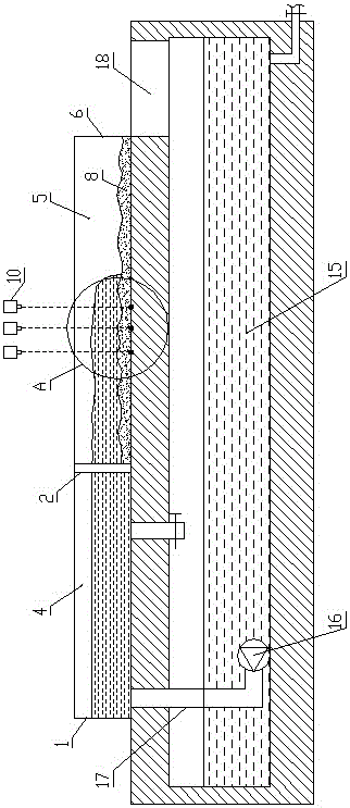
图1是本发明的结构示意图;Fig. 1 is the structural representation of the present invention;
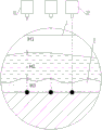
图2是图1中A处的放大图;Fig. 2 is the enlarged view of A place in Fig. 1;
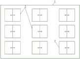
图3是图1中坝体的右视图;Fig. 3 is the right side view of the dam body in Fig. 1;
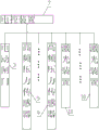
图4是本发明的控制原理图;Fig. 4 is the control principle diagram of the present invention;
图5是电控装置与激光装置相连接的原理图。FIG. 5 is a schematic diagram of the connection between the electronic control device and the laser device.
具体实施方式Detailed ways
如图1至图5所示,本发明的洪水作用下河床动态变化的模拟装置包括河道模拟槽1,河道模拟槽1内设有坝体2,坝体2上设有电动闸门3;电动闸门3可以设置1个较大的泄洪用电动闸门,也可以设置多个较小的泄洪用电动闸门。As shown in FIGS. 1 to 5 , the simulation device for the dynamic change of the river bed under the action of flooding of the present invention includes a river channel simulation tank 1, a dam body 2 is arranged in the river channel simulation tank 1, and an
坝体2上游侧的河道模拟槽1形成蓄水区4,坝体2下游侧的河道模拟槽1形成洪水模拟区5,洪水模拟区5的下游端设有出水口6,电动闸门3连接有电控装置7并通过电控装置7控制电动闸门3的启闭,如电控装置7通过电动推杆推开电动闸门3;电控装置打开电动闸门为常规技术,不再详述;The river channel simulation tank 1 on the upstream side of the dam body 2 forms a water storage area 4, and the river channel simulation tank 1 on the downstream side of the dam body 2 forms a
洪水模拟区5的底部铺设有与模拟河段河床砂的硬度相同的砂层8,砂层8下方的河道模拟槽1的底壁上设有若干安装孔,各安装孔内分别安装有一个高频压力传感器9,高频压力传感器9的信号线紧贴河道模拟槽1的底壁铺设并在引出河道模拟槽1后与电控装置7相连接;The bottom of the
各高频压力传感器9的正上方一一对应设有激光装置10,各激光装置10均高于预定的洪水水位并分别与电控装置7相连接;电控装置7接收激光装置10从发射激光到接收到返回激光的时间差信息,根据下述砂层8实时厚度计算公式计算出各激光装置10所对应的模拟河床的砂层8的实时厚度:Directly above each high-

H3为高频压力传感器9处模拟河床的砂层8的实时厚度,单位为米,为待计算量;H3 is the real-time thickness of the
H为激光装置10与其对应的高频压力传感器9之间的距离,单位为米,为安装本发明的洪水作用下河床动态变化的模拟装置时已经固定的已知量;H is the distance between the
T为激光装置10测量的从发射激光到接收到返回激光的时间差,单位为秒,为测量获得的已知量;T is the time difference measured by the
v1是激光在空气中传播速度299792458米/秒;v1 is the propagation speed of the laser in the air 299792458 m/s;
v2是激光在水中的传播速度225000000米/秒;v2 is the propagation speed of the laser in water 225000000 m/s;
d2为水的密度1000千克/立方米;d2 is the density of water 1000 kg/m3;
d3为砂层8的密度,单位为千克/立方米;d3为测量得到的已知量;d3 is the density of the
P为高频压力传感器9监测到的压强值,单位为帕斯卡(牛顿/平方米);P is the pressure value monitored by the high-
g为重力常数,为9.8N/kg(牛顿/千克);g is the gravitational constant, which is 9.8N/kg (Newton/kg);
所述激光装置10发射激光的频率与高频压力传感器9的测量频率相同并均大于100Hz。The frequency of laser light emitted by the
电控装置7优选采用台式计算机或笔记本电脑,也可以采用连接有显示屏的单片机或集成电路。The
所述各高频压力传感器9在同一水平面内呈矩阵式分布。The high-
激光装置10包括激光发射模块11、激光接收模块12、计时模块13和控制模块14,控制模块14连接激光发射模块11、激光接收模块12和计时模块13;控制模块14通过线路与电控装置7相连接。The
本发明还公开了使用上述洪水作用下河床动态变化的模拟装置进行的多点实时监测方法,依次按以下步骤进行:The invention also discloses a multi-point real-time monitoring method performed by using the above-mentioned simulation device for dynamic changes of the river bed under the action of flood, which is performed in sequence according to the following steps:
第一步骤是准备步骤:安装好洪水作用下河床动态变化的模拟装置,安装时精确控制并记录激光装置10与高频压力传感器9之间的距离H(也可以在洪水模拟区5铺设砂层8前通过激光装置10得出精确的H值);使用比重杯测量砂层8的实际密度作为d3的值;使用比重杯测量物质的密度为常规技术,具体操作不再详述。The first step is the preparation step: install the simulation device for the dynamic change of the river bed under the action of the flood, and accurately control and record the distance H between the
第二步骤是蓄水步骤,在蓄水区4内蓄水至实验预定水位;图1中标号15为设置在河道模拟槽下方的水源,标号16为潜水泵,标号17为进水管,标号18为回水孔。打开潜水泵16即可将水源中的水送入蓄水区4进行蓄水。模拟洪水时,洪水最终经出水口6并通过回水孔18回流入水源。The second step is the water storage step, and the water is stored in the water storage area 4 to the predetermined water level of the experiment; in FIG. 1, the
第三步骤是泄洪模拟及测量步骤;The third step is the flood discharge simulation and measurement step;
通过电控装置7打开各激光装置10,电控装置7持续接收各激光装置10返回的激光由发出至返回的时间差信息;Each
通过电控装置7控制电动闸门3打开,模拟泄洪;洪水的水头(即洪水向前流动的前端)通过洪水模拟区5时冲刷模拟河床的砂层8,使砂层8厚度发生动态变化;在此过程中,电控装置7根据砂层8实时厚度计算公式计算出各激光装置10所对应的模拟河床的砂层8的实时厚度H3并予以存储,实现在洪水作用下实时地对河床动态变化进行多点同时测量。得到河床在洪水作用下的三维动态变化的基础数据。The
由于本发明测量砂层8的时实厚度时是由上向下测量,因此无须河道模拟槽1边壁透明,也不会因在砂层8的不同深度埋设传感器并监测传感器浮出水面的信号而对实验带来干扰,并提高测量的精确度。Since the real-time thickness of the
本发明不再采用传统的探测锤、探测杆等,通过激光装置10和高频压力传感器9实现洪水发生时的实时测量。The present invention no longer uses traditional detection hammers, detection rods, etc., and realizes real-time measurement when flood occurs through the
洪水作用下河床地形演变非常快速,激光装置10发射激光的频率与高频压力传感器9的测量频率相同并均大于100Hz,一方面能够对快速演变的河床进行充分的实时测量、避免测量频率较低造成测量出的河床地形演变过于粗糙,使得根据测量结果绘制的三维演化图线条更加平滑,不会出现某处河床厚度跳升跳降的现象;另一方面激光装置10和高频压力传感器9同频工作,也增强了测量工作的同步性和准确性,并且避免频率不同步造成高频件的无谓能耗。The topography of the river bed evolves very rapidly under the action of flooding, and the frequency of the laser emitted by the
在第二步骤结束之后、第三步骤开始之前,进行润湿作业;After the end of the second step and before the start of the third step, the wetting operation is performed;
润湿作业是指向砂层8注水以使砂层8湿润,使水淹没砂层8以模拟洪水到来前河道中具有一定水位情况。The wetting operation is to inject water into the
干砂河床与湿砂河床在洪水冲刷作用下的演进规律有所不同,进行润湿可以避免干湿不同带来的实验误差(干砂可能固结)。水淹没砂层8能够更逼真地模拟洪水到来前的河道中具有一定水位的情况,增强这一情况下实验的准确度。The evolution law of the dry sand river bed and the wet sand river bed under the action of flood erosion is different. Wetting can avoid the experimental error caused by the difference of dry and wet (dry sand may be consolidated). The water-submerged
洪水发生时水流湍急,此时不便于普通人员进行观察。河床由于冲刷搅起的砂粒会被快速的带向下游,不会对上部的水体造成干扰,即使有小部分砂停留在水体里,但总体依然透明,不影响激光对水体的穿透性,这是本发明的设计基础,虽然原理简单,但是克服了普通人员对洪水清浊程度的误解。When the flood occurs, the water flow is turbulent, and it is not convenient for ordinary people to observe at this time. The sand particles stirred up by the scouring of the river bed will be quickly carried downstream without disturbing the upper water body. Even if a small part of the sand stays in the water body, it is still transparent and does not affect the penetration of the laser into the water body. It is the design basis of the present invention. Although the principle is simple, it overcomes the misunderstanding of ordinary people on the degree of turbidity of the flood.
洪水水头通过河段后或者越过河道进入农田村镇后,水流趋于平缓,此时便于普通人员进行观察,新闻报道中的画面也是此时的画面。由于水流趋于平缓,因此会有砂粒或者杂物进入上部水体,使水体变得混浊,不适宜使用激光进行测量。因此在普通人的认识中,洪水多是混浊的,不适宜使用激光进行测量,这也造成了以往没有一项专利使用激光来测量洪水发生时的河床,最多使用激光来测量水位(测量水位不需要穿透洪水)。After the flood head passes through the river section or crosses the river into the farmland villages and towns, the water flow tends to be gentle, which is convenient for ordinary people to observe at this time, and the pictures in the news reports are also the pictures at this time. Since the water flow tends to be gentle, there will be sand or debris entering the upper water body, making the water body turbid, and it is not suitable to use a laser for measurement. Therefore, in the understanding of ordinary people, floods are mostly turbid, and it is not suitable to use lasers for measurement, which also results in no patent using lasers to measure the riverbed when floods occur. Flood penetration is required).
砂层实时厚度计算公式的推导过程:The derivation process of the real-time thickness calculation formula of sand layer:
式①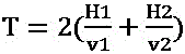


由式①推出:式②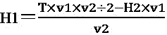
式③H=H1+H2+H3;H为激光装置10到其对应的高频压力传感器9之间的总距离。H3为高频压力传感器9处模拟河床的砂层8的实时厚度,即砂层8厚度。Formula ③H=H1+H2+H3; H is the total distance between the
由式③推出式④:H3=H-H1-H2;From
式⑤
将式④代入式⑤得式⑥:
由式⑥得式⑦
将式⑦代入式②得式⑧
将式⑦和式⑧代入式③得:Substitute

以上实施例仅用以说明而非限制本发明的技术方案,尽管参照上述实施例对本发明进行了详细说明,本领域的普通技术人员应当理解:依然可以对本发明进行修改或者等同替换,而不脱离本发明的精神和范围的任何修改或局部替换,其均应涵盖在本发明的权利要求范围当中。The above embodiments are only used to illustrate rather than limit the technical solutions of the present invention. Although the present invention has been described in detail with reference to the above embodiments, those of ordinary skill in the art should understand that the present invention can still be modified or equivalently replaced without departing from the Any modification or partial replacement of the spirit and scope of the present invention should be included in the scope of the claims of the present invention.
Claims (5)

Priority Applications (1)
| Application Number | Priority Date | Filing Date | Title |
|---|---|---|---|
| CN201910820133.6A CN110485363B (en) | 2019-08-31 | 2019-08-31 | Simulation device and multi-point real-time monitoring method for dynamic change of river bed under flood |
Applications Claiming Priority (1)
| Application Number | Priority Date | Filing Date | Title |
|---|---|---|---|
| CN201910820133.6A CN110485363B (en) | 2019-08-31 | 2019-08-31 | Simulation device and multi-point real-time monitoring method for dynamic change of river bed under flood |
Publications (2)
| Publication Number | Publication Date |
|---|---|
| CN110485363A CN110485363A (en) | 2019-11-22 |
| CN110485363B true CN110485363B (en) | 2020-11-20 |
Family
ID=68555970
Family Applications (1)
| Application Number | Title | Priority Date | Filing Date |
|---|---|---|---|
| CN201910820133.6A Active CN110485363B (en) | 2019-08-31 | 2019-08-31 | Simulation device and multi-point real-time monitoring method for dynamic change of river bed under flood |
Country Status (1)
| Country | Link |
|---|---|
| CN (1) | CN110485363B (en) |
Families Citing this family (3)
| Publication number | Priority date | Publication date | Assignee | Title |
|---|---|---|---|---|
| CN112530226B (en) * | 2020-12-13 | 2023-10-27 | 中国船舶重工集团公司七五0试验场 | ROV simulation training system for auxiliary operation of turbid water area |
| CN113551829B (en) * | 2021-07-20 | 2022-04-01 | 中国海洋大学 | Scouring monitoring device and method for monitoring scouring of foundation structure of offshore wind turbines |
| CN118052169B (en) * | 2024-04-16 | 2024-06-11 | 长江水利委员会长江科学院 | Scour stability duration calculation method and system for gravel river channel downstream of reservoir |
Family Cites Families (7)
| Publication number | Priority date | Publication date | Assignee | Title |
|---|---|---|---|---|
| JP2001296151A (en) * | 2000-04-14 | 2001-10-26 | Foundation Of River & Basin Integrated Communications Japan | Optical fiber scour sensor and scour detection system using the same |
| CN101666720B (en) * | 2009-09-08 | 2011-05-11 | 清华大学 | Scouring model experimental device of underground silt and method |
| CN102605738B (en) * | 2012-01-13 | 2013-06-05 | 河海大学 | Method for monitoring change of internal force of resin mortar block during riverbed blowing up scouring period of hyper-concentration sediment flood |
| CN107761656B (en) * | 2017-11-28 | 2024-02-06 | 长江水利委员会长江科学院 | Flood washing and accumulating fan water tank test system and flood washing and accumulating parameter determination method |
| CN109024467A (en) * | 2018-08-29 | 2018-12-18 | 昆明理工大学 | A kind of mud-rock flow dam break imitative experimental appliance under difference ditch bed form |
| CN109883647B (en) * | 2019-01-16 | 2021-08-24 | 水利部交通运输部国家能源局南京水利科学研究院 | A method and device for dynamically measuring the evolution process of dam failure |
| CN110362925B (en) * | 2019-07-16 | 2020-05-19 | 中国水利水电科学研究院 | Method for simulating overtopping and bursting flood numerical value of earth and rockfill dam comprising reservoir area |
-
2019
- 2019-08-31 CN CN201910820133.6A patent/CN110485363B/en active Active
Also Published As
| Publication number | Publication date |
|---|---|
| CN110485363A (en) | 2019-11-22 |
Similar Documents
| Publication | Publication Date | Title |
|---|---|---|
| CN108254032B (en) | River ultrasonic time difference method flow calculation method | |
| Nadaoka et al. | Structure of the turbulent flow field under breaking waves in the surf zone | |
| CN106018739B (en) | A kind of tidal flat Creek system geomorphic evolution physical model experiment system and method | |
| WO2022021587A1 (en) | Test system for simulating multi-field coupling effect of offshore wind power rock-socketed pile | |
| CN100588915C (en) | Channel Flow Meter and Its Measuring Method | |
| CN109253765A (en) | River discharge monitors measuring system and method for calculating flux on-line | |
| CN109612685B (en) | Integrated measuring device and method for flow speed and depth of water tank test | |
| CN110659783B (en) | Method for predicting longitudinal distribution of average flow velocity of cross section of vegetation community river channel | |
| CN108519212A (en) | Device and method for monitoring landslide surge height and dynamic pressure with adjustable angle | |
| CN115391904B (en) | River bank collapse early warning method and system | |
| CN110991822A (en) | A 3D Hydrodynamic Numerical Simulation Method Based on Oblique Image Modeling | |
| CN110485363A (en) | Flood acts on the simulator and multiple spot method of real-time of lower riverbed dynamic change | |
| CN113700055B (en) | Test method for simulating erosion of solidified soil in offshore wind power pile construction process | |
| CN110986892A (en) | A kind of runoff velocity and flow monitoring method, monitoring device and monitoring system | |
| CN115078688A (en) | Solid simulation method for influence of check dam arrangement on small watershed torrential rain and torrential flood process | |
| CN114357905A (en) | Method for predicting flow velocity and turbulent energy vertical distribution along course of vegetation area under influence of real form vegetation | |
| CN104019805B (en) | High-sand-content turbid water density current detection method | |
| CN119416704A (en) | Hydrodynamic model system based on MIKE 21FM model and parameter automatic judgment setting, selection and verification method | |
| CN116296266A (en) | A structure optimization design method for artificial fish reef | |
| CN202794218U (en) | Real-time on-line depth averaged velocity measurement apparatus | |
| CN116220665B (en) | Gas invasion early-stage monitoring experimental device and experimental method based on pressure wave method | |
| CN206479214U (en) | Ultrasonic open-channel meter | |
| Wang et al. | Propagation Mechanism of Deep‐Water Impulse Waves Generated by Landslides in V‐Shaped River Channels of Mountain Valleys: Physical Model of Regular Rigid Block | |
| CN109680645A (en) | A kind of construction density current test layer knot environment water device and method | |
| CN102865994A (en) | Test device and test method of occurrence and movement rule of temperature difference flow backward density current |
Legal Events
| Date | Code | Title | Description |
|---|---|---|---|
| PB01 | Publication | ||
| PB01 | Publication | ||
| SE01 | Entry into force of request for substantive examination | ||
| SE01 | Entry into force of request for substantive examination | ||
| GR01 | Patent grant | ||
| GR01 | Patent grant |