CN110355027B - Rotary spraying equipment for steel pipe production and processing and spraying method thereof - Google Patents
Rotary spraying equipment for steel pipe production and processing and spraying method thereof Download PDFInfo
- Publication number
- CN110355027B CN110355027B CN201910761130.XA CN201910761130A CN110355027B CN 110355027 B CN110355027 B CN 110355027B CN 201910761130 A CN201910761130 A CN 201910761130A CN 110355027 B CN110355027 B CN 110355027B
- Authority
- CN
- China
- Prior art keywords
- steel pipe
- rotating drum
- rotary spraying
- support frame
- frame
- Prior art date
- Legal status (The legal status is an assumption and is not a legal conclusion. Google has not performed a legal analysis and makes no representation as to the accuracy of the status listed.)
- Active
Links
Images

Classifications
-
- B—PERFORMING OPERATIONS; TRANSPORTING
- B05—SPRAYING OR ATOMISING IN GENERAL; APPLYING FLUENT MATERIALS TO SURFACES, IN GENERAL
- B05B—SPRAYING APPARATUS; ATOMISING APPARATUS; NOZZLES
- B05B13/00—Machines or plants for applying liquids or other fluent materials to surfaces of objects or other work by spraying, not covered by groups B05B1/00 - B05B11/00
- B05B13/02—Means for supporting work; Arrangement or mounting of spray heads; Adaptation or arrangement of means for feeding work
- B05B13/0221—Means for supporting work; Arrangement or mounting of spray heads; Adaptation or arrangement of means for feeding work characterised by the means for moving or conveying the objects or other work, e.g. conveyor belts
-
- B—PERFORMING OPERATIONS; TRANSPORTING
- B05—SPRAYING OR ATOMISING IN GENERAL; APPLYING FLUENT MATERIALS TO SURFACES, IN GENERAL
- B05B—SPRAYING APPARATUS; ATOMISING APPARATUS; NOZZLES
- B05B13/00—Machines or plants for applying liquids or other fluent materials to surfaces of objects or other work by spraying, not covered by groups B05B1/00 - B05B11/00
- B05B13/02—Means for supporting work; Arrangement or mounting of spray heads; Adaptation or arrangement of means for feeding work
- B05B13/0278—Arrangement or mounting of spray heads
-
- B—PERFORMING OPERATIONS; TRANSPORTING
- B05—SPRAYING OR ATOMISING IN GENERAL; APPLYING FLUENT MATERIALS TO SURFACES, IN GENERAL
- B05B—SPRAYING APPARATUS; ATOMISING APPARATUS; NOZZLES
- B05B13/00—Machines or plants for applying liquids or other fluent materials to surfaces of objects or other work by spraying, not covered by groups B05B1/00 - B05B11/00
- B05B13/02—Means for supporting work; Arrangement or mounting of spray heads; Adaptation or arrangement of means for feeding work
- B05B13/04—Means for supporting work; Arrangement or mounting of spray heads; Adaptation or arrangement of means for feeding work the spray heads being moved during spraying operation
- B05B13/0421—Means for supporting work; Arrangement or mounting of spray heads; Adaptation or arrangement of means for feeding work the spray heads being moved during spraying operation with rotating spray heads
-
- B—PERFORMING OPERATIONS; TRANSPORTING
- B08—CLEANING
- B08B—CLEANING IN GENERAL; PREVENTION OF FOULING IN GENERAL
- B08B1/00—Cleaning by methods involving the use of tools
- B08B1/10—Cleaning by methods involving the use of tools characterised by the type of cleaning tool
- B08B1/12—Brushes
Landscapes
- Spray Control Apparatus (AREA)
Abstract
一种钢管生产加工用旋转喷涂设备,涉及钢管加工设备技术领域,包括:工作台、旋转喷涂装置、支撑机构,所述工作台设置为方桌结构,所述工作台的桌面固定有旋转喷涂装置,所述旋转喷涂装置的两侧设有支撑机构;其中,所述旋转喷涂装置包括机架和旋转筒,所述机架设置为方形板,所述机架的一端设有圆孔,所述旋转筒安装于圆孔内,所述旋转筒设置为圆筒状,所述旋转筒在机架的两端向外部伸出,所述机架的其中一端且位于旋转筒的外壁设有轮齿。本发明将旋转筒设置为圆筒状,并将旋转筒设置在桌面上,使得弯管从筒腔的一端穿过旋转筒,旋转筒端面的喷漆嘴对钢管表面进行喷涂,提高该旋转喷涂设备的工作能力。

A rotary spraying equipment for steel pipe production and processing relates to the technical field of steel pipe processing equipment, comprising: a workbench, a rotary spraying device, and a support mechanism, the workbench is configured as a square table structure, and the table top of the workbench is fixed with a rotary spraying device, The two sides of the rotary spraying device are provided with support mechanisms; wherein, the rotary spraying device includes a frame and a rotating drum, the frame is configured as a square plate, and one end of the frame is provided with a circular hole, and the rotating The drum is installed in the circular hole, the rotating drum is arranged in a cylindrical shape, the rotating drum protrudes to the outside at both ends of the frame, and one end of the frame and the outer wall of the rotating drum are provided with gear teeth. In the present invention, the rotating drum is set in a cylindrical shape, and the rotating drum is set on the table top, so that the bent pipe passes through the rotating drum from one end of the cylinder cavity, and the paint spray nozzle on the end face of the rotating drum sprays the surface of the steel pipe, thereby improving the rotary spraying equipment. work ability.
Description
技术领域technical field
本发明涉及钢管加工设备技术领域,具体涉及一种钢管生产加工用旋转喷涂设备及其喷涂方法。The invention relates to the technical field of steel pipe processing equipment, in particular to a rotary spraying equipment for steel pipe production and processing and a spraying method thereof.
背景技术Background technique
传统的成品钢管成型一般是靠冷轧成型,成型后的钢管表面一般都没有进行喷涂漆处理,在建设工程中,从开始到完工都要经过2-3年左右的工期,这样,钢管在户外风吹日晒雨淋很容易生锈腐烛,使钢管的使用寿命大大缩短,为了提高钢管的防锈能力,目前的办法是采用人工对钢管的内和外壁进行喷漆,传统的人工喷涂的方式劳动强度大,为工作者带来较大的劳动量,并且人工难以对管道的内壁进行喷涂作业。The traditional finished steel pipe forming is generally formed by cold rolling, and the surface of the formed steel pipe is generally not treated with spray paint. In the construction project, it takes about 2-3 years from the beginning to the completion of the construction period. Wind, sun and rain can easily rust the candle, which greatly shortens the service life of the steel pipe. In order to improve the rust-proof ability of the steel pipe, the current method is to manually spray the inner and outer walls of the steel pipe. The traditional manual spraying method The labor intensity is high, which brings a large amount of labor to the workers, and it is difficult to manually spray the inner wall of the pipeline.
专利号为CN201910041845.8的发明专利公开了一种钢管内外壁自动喷涂机的工作方法,包括有内壁喷涂机构、外壁喷涂机构、工作台和转动机构,该发明的有意效果是通过外壁喷涂机构能够自动对钢管的外壁进行喷涂作业,自动化程度高,无需工作者手动对钢管外壁进行喷涂作业降低了工作者的劳动强度。The invention patent with the patent number of CN201910041845.8 discloses a working method of an automatic spraying machine for the inner and outer walls of steel pipes, including an inner wall spraying mechanism, an outer wall spraying mechanism, a worktable and a rotating mechanism. The intentional effect of the invention is that the outer wall spraying mechanism can The outer wall of the steel pipe is automatically sprayed, with a high degree of automation, and it is not necessary for workers to manually spray the outer wall of the steel pipe, which reduces the labor intensity of the workers.
但是上述专利在现实生活的使用中依旧存在以下问题:However, the above-mentioned patents still have the following problems in the use of real life:
第一,该发明装置只能对直管钢管进行喷涂,对于工程中的各类弯管难以清洗;First, the device of the invention can only spray the straight pipe, and it is difficult to clean all kinds of elbows in the project;
第二,钢管在冷轧成型后,表面容易附着车间内的微小杂质,在喷涂之前未对钢管表面清行清刷,容易使喷涂后的钢管表面不光滑。Second, after the steel pipe is cold-rolled and formed, the surface of the steel pipe is easy to adhere to the small impurities in the workshop, and the surface of the steel pipe is not cleaned before spraying, which is easy to make the surface of the steel pipe after spraying not smooth.
发明内容SUMMARY OF THE INVENTION
针对现有技术中的问题,本发明的目的在于提供一种钢管生产加工用旋转喷涂设备及其喷涂方法,解决现有装置中不能对弯管表面进行喷涂的技术问题。In view of the problems in the prior art, the purpose of the present invention is to provide a rotary spraying equipment for steel pipe production and processing and a spraying method thereof, so as to solve the technical problem that the surface of the elbow cannot be sprayed in the existing device.
本发明所要解决的技术问题采用以下的技术方案来实现:一种钢管生产加工用旋转喷涂设备,包括:工作台、旋转喷涂装置、支撑机构,所述工作台设置为方桌结构,所述工作台的桌面固定有旋转喷涂装置,所述旋转喷涂装置的两侧设有支撑机构;The technical problem to be solved by the present invention is achieved by the following technical solutions: a rotary spraying equipment for steel pipe production and processing, comprising: a workbench, a rotary spraying device, and a support mechanism, the workbench is configured as a square table structure, and the workbench A rotary spraying device is fixed on the table top of the device, and the two sides of the rotary spraying device are provided with supporting mechanisms;
其中,所述旋转喷涂装置包括机架和旋转筒,所述机架设置为方形板,所述机架的一端设有圆孔,所述旋转筒安装于圆孔内,所述旋转筒设置为圆筒状,所述旋转筒在机架的两端向外部伸出,所述机架的其中一端且位于旋转筒的外壁设有轮齿;Wherein, the rotary spraying device includes a frame and a rotating cylinder, the frame is configured as a square plate, one end of the frame is provided with a circular hole, the rotating cylinder is installed in the circular hole, and the rotating cylinder is set to Cylindrical shape, the rotating drum protrudes to the outside at both ends of the rack, and one end of the rack is located on the outer wall of the rotating drum with gear teeth;
所述旋转筒的下方设有伺服电机,所述伺服电机固定在工作台的桌面上;所述伺服电机的轴出端设有齿轮,所述齿轮与轮齿啮合;A servo motor is arranged below the rotating drum, and the servo motor is fixed on the table top of the workbench; a gear is arranged at the shaft outlet end of the servo motor, and the gear meshes with the gear teeth;
所述机架的另一端且位于旋转筒的端面安装有喷漆嘴,所述喷漆嘴共设有多个,所述喷漆嘴在旋转筒的端面均匀分布;The other end of the frame and the end face of the rotating drum are installed with paint spray nozzles, a plurality of the paint spray nozzles are arranged in total, and the paint spray nozzles are evenly distributed on the end face of the rotating drum;
所述旋转筒的轴心位置设有筒腔,所述筒腔两端贯通,所述筒腔的其中一端设有刷毛,所述刷毛在筒腔的内壁均匀布置。A cylindrical cavity is provided at the axial center position of the rotating drum, two ends of the cylindrical cavity are connected, and one end of the cylindrical cavity is provided with bristles, and the bristles are evenly arranged on the inner wall of the cylindrical cavity.
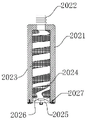
作为本发明的一种优选技术方案,为了提高喷漆嘴的喷力以及喷漆的均匀性,所述喷漆嘴包括喷漆嘴本体,所述喷漆嘴本体设为圆筒状,所述喷漆嘴本体的顶端设有接入口,所述喷漆嘴本体的内部设有螺旋管,所述接入口与螺旋管连通,所述螺旋管与直流腔连通,所述直流腔的腔内安装有扰流扇,所述扰流扇的底部设有过滤网,所述过滤网固定在喷漆嘴本体的底端。As a preferred technical solution of the present invention, in order to improve the spraying force of the paint spray nozzle and the uniformity of painting, the paint spray nozzle includes a paint spray nozzle body, the paint spray nozzle body is set to a cylindrical shape, and the top of the paint spray nozzle body is There is an access port, a spiral tube is arranged inside the paint spray nozzle body, the access port is communicated with the spiral tube, the spiral tube is communicated with the direct current cavity, and a spoiler fan is installed in the cavity of the direct current cavity. The bottom of the spoiler fan is provided with a filter screen, and the filter screen is fixed on the bottom end of the spray nozzle body.
作为本发明的一种优选技术方案,为了便于作业人员将钢管处于旋转筒的轴心位置,所述支撑机构包括第一支撑架和第二支撑架,所述第一支撑架布置于所述旋转喷涂装置的一侧边,所述第二支撑架布置于所述旋转喷涂装置的另一侧边;As a preferred technical solution of the present invention, in order to facilitate the operator to place the steel pipe at the axis of the rotating drum, the support mechanism includes a first support frame and a second support frame, and the first support frame is arranged on the rotating drum. One side of the spraying device, the second support frame is arranged on the other side of the rotating spraying device;
所述工作台的底部设有支撑杆,所述支撑板设置为U形杆,且U形板的一端穿过工作台连接于第一支撑架的底部,U形板的另一端穿过工作台连接于第二支撑架的底部;The bottom of the workbench is provided with a support rod, the support plate is set as a U-shaped rod, and one end of the U-shaped plate passes through the workbench and is connected to the bottom of the first support frame, and the other end of the U-shaped plate passes through the workbench connected to the bottom of the second support frame;
所述工作台的底部安装有线性直驱电机,所述支撑杆固定在线性直驱电机上。A linear direct drive motor is installed on the bottom of the worktable, and the support rod is fixed on the linear direct drive motor.
作为本发明的一种优选技术方案,为了便于调节第一支撑架以及第二支撑架的高度,便于作业人员将钢管处于旋转筒的轴心位置,所述第二支撑架的结构特征设置为与第一支撑架的结构特征完全相同,所述第一支撑架设置为U形结构,且第一支撑架的U形结构内安装有滚筒,所述滚筒的外壁设有腰槽,所述腰槽设置为圆弧状,所述滚筒的两端设有轴杆,所述轴杆的两端固定在第一支撑架上。As a preferred technical solution of the present invention, in order to facilitate adjustment of the heights of the first support frame and the second support frame, and to facilitate the operator to place the steel pipe at the axis of the rotating drum, the structural features of the second support frame are set to The structural features of the first support frame are exactly the same. The first support frame is arranged in a U-shaped structure, and a roller is installed in the U-shaped structure of the first support frame. The outer wall of the roller is provided with a waist groove, and the waist groove It is arranged in an arc shape, the two ends of the drum are provided with shaft rods, and the two ends of the shaft rod are fixed on the first support frame.
作为本发明的一种优选技术方案,为了避免将喷涂完成后的钢管涂漆面粘附在滚筒的表面,所述滚筒的外壁包裹有聚四氟塑料布。As a preferred technical solution of the present invention, in order to avoid adhering the painted surface of the steel pipe after spraying to the surface of the drum, the outer wall of the drum is wrapped with polytetrafluoroplastic cloth.
作为本发明的一种优选技术方案,为了提高喷漆嘴对钢管表面喷涂的均匀性,提高钢管在旋转筒内的匀速移动,所述第二支撑架包括第二伺服电机,所述第二伺服电机设置在第二支撑架的侧边,且所述第二伺服电机与轴杆固定连接。As a preferred technical solution of the present invention, in order to improve the uniformity of spraying the surface of the steel pipe by the paint spray nozzle and improve the uniform movement of the steel pipe in the rotating drum, the second support frame includes a second servo motor, and the second servo motor It is arranged on the side of the second support frame, and the second servo motor is fixedly connected with the shaft.
作为本发明的一种优选技术方案,为了使喷漆嘴对钢管外壁喷涂均匀,所述旋转筒的回转角度设置为±45°。As a preferred technical solution of the present invention, in order to make the paint spray nozzle evenly spray the outer wall of the steel pipe, the rotation angle of the rotating drum is set to ±45°.
一种钢管生产加工用旋转喷涂方法,包括以下步骤:A rotary spraying method for steel pipe production and processing, comprising the following steps:
a、伺服电机得电,驱动旋转筒转动;a. The servo motor is powered to drive the rotating drum to rotate;
b、将待喷涂的钢管从旋转喷涂装置的一端伸入筒腔内;b. Extend the steel pipe to be sprayed into the cylinder cavity from one end of the rotary spraying device;
c、筒腔内壁的刷毛对钢管的表面进行清刷;c. The bristles on the inner wall of the cylinder cavity clean the surface of the steel pipe;
d、钢管在筒腔内匀速移动,经过喷漆嘴时,喷漆嘴对钢管的外壁喷洒油漆液,并在±45°的可旋转范围内反复喷涂,完成对钢管外壁的均匀喷涂。d. The steel pipe moves at a constant speed in the cylinder cavity. When passing through the spray nozzle, the spray nozzle sprays the paint liquid on the outer wall of the steel pipe, and sprays repeatedly within the rotatable range of ±45° to complete the uniform spraying on the outer wall of the steel pipe.
与现有技术相比,本发明至少包括以下有益效果:Compared with the prior art, the present invention at least includes the following beneficial effects:
一、本发明将旋转筒设置为圆筒状,并将旋转筒设置在桌面上,使得弯管从筒腔的一端穿过旋转筒,旋转筒端面的喷漆嘴对钢管表面进行喷涂,提高该旋转喷涂设备的工作能力;1. In the present invention, the rotating cylinder is set in a cylindrical shape, and the rotating cylinder is set on the table top, so that the elbow passes through the rotating cylinder from one end of the cylinder cavity, and the paint spray nozzle on the end face of the rotating cylinder sprays the surface of the steel pipe to improve the rotation rate. The working ability of spraying equipment;
二、本发明在筒腔的一端设有刷毛,钢管从旋转筒的一端伸入筒腔内,先经过刷毛对钢管表面进行清刷,扫除钢管表面附着的微小杂质,使喷涂后的钢管表面更加光滑。2. In the present invention, bristles are provided at one end of the cylinder cavity, and the steel pipe extends into the cylinder cavity from one end of the rotating cylinder, and the surface of the steel pipe is first cleaned by the brush bristles to remove the tiny impurities attached to the surface of the steel pipe, so that the surface of the steel pipe after spraying is more smooth.
附图说明Description of drawings
下面结合附图和实施例对本发明进一步说明。The present invention will be further described below in conjunction with the accompanying drawings and embodiments.
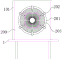
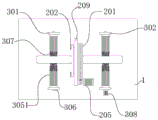
图1为本发明钢管生产加工用旋转喷涂设备的正视图;Fig. 1 is the front view of the rotary spraying equipment for steel pipe production and processing of the present invention;
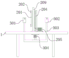
图2为本发明钢管生产加工用旋转喷涂设备移除第一支撑架后的正视图;Fig. 2 is the front view after the first support frame is removed by the rotary spraying equipment for steel pipe production and processing of the present invention;
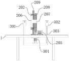
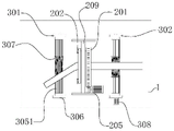
图3为本发明钢管生产加工用旋转喷涂设备的左视图;Fig. 3 is the left side view of the rotary spraying equipment for steel pipe production and processing of the present invention;
图4为本发明钢管生产加工用旋转喷涂设备的剖面图;Fig. 4 is the sectional view of the rotary spraying equipment for steel pipe production and processing of the present invention;
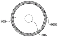
图5为本发明滚筒的端面结构示意图;Fig. 5 is the end face structure schematic diagram of the roller of the present invention;
图6为本发明喷漆嘴的剖面结构示意图;Fig. 6 is the sectional structure schematic diagram of the paint spray nozzle of the present invention;
图7为本发明直管钢管放置在该旋转喷涂设备上喷涂的结构示意图;Fig. 7 is the structural representation that the straight pipe steel pipe of the present invention is placed on this rotary spraying equipment and sprayed;
图8为本发明弯管钢管放置在该旋转喷涂设备上喷涂的结构示意图;Fig. 8 is the structural representation that the pipe bend of the present invention is placed on this rotary spraying equipment and sprayed;
图中:1、工作台,101、防护罩,2、旋转喷涂装置,201、旋转筒,202、喷漆嘴,2021、喷漆嘴本体,2022、接入口,2023、填塞物,2024、螺旋管,2025、直流腔,2026、扰流扇,2027、过滤网,203、刷毛,204、轮齿,205、伺服电机,206、筒腔,207、圆孔,208、滚动轴承,209、机架,3、支撑机构,301、第一支撑架,302、第二支撑架,303、支撑杆,304、线性直驱电机,305、滚筒,3051、聚四氟塑料布,306、轴杆,307、腰槽,308、第二伺服电机。In the figure: 1. Workbench, 101, protective cover, 2. Rotary spraying device, 201, rotating drum, 202, spray nozzle, 2021, spray nozzle body, 2022, access port, 2023, packing, 2024, spiral tube, 2025, DC cavity, 2026, spoiler fan, 2027, filter, 203, bristles, 204, gear teeth, 205, servo motor, 206, cylinder cavity, 207, round hole, 208, rolling bearing, 209, frame, 3 , support mechanism, 301, first support frame, 302, second support frame, 303, support rod, 304, linear direct drive motor, 305, roller, 3051, PTFE plastic cloth, 306, shaft, 307, waist Slot, 308, second servo motor.
具体实施方式Detailed ways
以下结合附图对本发明的实施例进行详细说明,但是本发明可以由权利要求限定和覆盖的多种不同方式实施。The embodiments of the present invention are described in detail below with reference to the accompanying drawings, but the present invention can be implemented in many different ways as defined and covered by the claims.
为了使本发明实现的技术手段、创作特征、达成目的与功效易于明白了解,下面结合具体图示,进一步阐述本发明。In order to make it easy to understand the technical means, creation features, achieved goals and effects of the present invention, the present invention will be further described below with reference to the specific figures.
需要说明的是,当元件被成称为“固定于”另一个元件,它可以是另一个元件上或者也可以是存在居中的元件。当一个元件被认为是“连接”另一个元件,它可以是直接连接到另一个元件或者可能同时存在居中元件。本文所使用的术语“垂直的”、“水平的”、“左”“右”以及类似的表达只是为了说明的目的,并不表示是唯一的实施方式。It should be noted that when an element is referred to as being "fixed to" another element, it can be on the other element or an intervening element may also be present. When an element is referred to as being "connected" to another element, it can be directly connected to the other element or intervening elements may also be present. The terms "vertical," "horizontal," "left," "right," and similar expressions used herein are for illustrative purposes only and do not represent the only embodiment.
实施例1Example 1
请参阅图1,图2,图3,图4,图7和图8,为一种钢管生产加工用旋转喷涂设备的整体结构示意图;包括:工作台1、旋转喷涂装置2、支撑机构3,工作台1设置为方桌结构,工作台1的桌面固定有旋转喷涂装置2,旋转喷涂装置2的两侧设有支撑机构3;Please refer to Fig. 1, Fig. 2, Fig. 3, Fig. 4, Fig. 7 and Fig. 8, which are schematic diagrams of the overall structure of a rotary spraying equipment for steel production and processing; including: a
其中,旋转喷涂装置2包括机架209和旋转筒201,机架209设置为方形板,机架209的两侧壁设有防护罩101,避免涂料在喷涂的过程中乱溅,提高该装置的安全性,机架209的一端设有圆孔,旋转筒201安装于圆孔内,旋转筒201设置为圆筒状,旋转筒201与圆孔的连接处设有滚动轴承208,旋转筒201在机架209的两端向外部伸出,机架209的其中一端且位于旋转筒201的外壁设有轮齿204;Among them, the rotary spraying device 2 includes a
旋转筒201的下方设有伺服电机205,伺服电机205固定在工作台1的桌面上;伺服电机205的轴出端设有齿轮,齿轮与轮齿204啮合;A
机架209的另一端且位于旋转筒201的端面安装有喷漆嘴202,喷漆嘴202共设有多个,喷漆嘴202在旋转筒201的端面均匀分布;其中,喷漆嘴的喷射口指向旋转筒201的轴心位置;The other end of the
旋转筒201的轴心位置设有筒腔206,筒腔206两端贯通,筒腔206的其中一端设有刷毛203,刷毛203在筒腔206的内壁均匀布置,使刷毛203在圆心位置形成圆孔207,便于作业人员在伸入钢管时找到圆心。A
一、本发明将旋转筒201设置为圆筒状,并将旋转筒201设置在工作台1的桌面上,使得弯管从筒腔206的一端穿过旋转筒201,旋转筒201端面的喷漆嘴202对钢管表面进行喷涂,提高该旋转喷涂设备的实用性;1. In the present invention, the
二、本发明在筒腔的一端设有刷毛,钢管从旋转筒的一端伸入筒腔内,先经过刷毛对钢管表面进行清刷,扫除钢管表面附着的微小杂质,使喷涂后的钢管表面更加光滑。2. In the present invention, bristles are provided at one end of the cylinder cavity, and the steel pipe extends into the cylinder cavity from one end of the rotating cylinder, and the surface of the steel pipe is first cleaned by the brush bristles to remove the tiny impurities attached to the surface of the steel pipe, so that the surface of the steel pipe after spraying is more smooth.
三、喷漆嘴202共设有多个,每一个喷漆嘴202对钢管表面进行喷涂,通过旋转筒201的回转角度设置为±45°,使多个喷漆嘴202对钢管表面进行均匀喷涂,其中,相邻两个喷漆嘴202还可单独外接两种不同的喷涂料,以便得喷涂在钢管表面的色泽均匀,性能稳定,涂料附着能力强,3. There are a plurality of
四、旋转筒201的回转角度设置为±45°,有利于避免旋转筒201端面上的每一个喷漆嘴202转动幅度过大,导致连接在喷漆嘴202端部的管道被牵扯脱离,且嘴漆嘴202在旋转筒201的端面共设有多个,旋转筒201的回转角度为±45°使得多个喷漆嘴202对钢管表面喷涂均匀,避免喷漆嘴202返程时回转角度过大,对钢管表面过于喷涂,4. The rotation angle of the
五、喷漆嘴202包括喷漆嘴本体2021,喷漆嘴本体2021设为圆筒状,喷漆嘴本体2021的顶端设有接入口2022,喷漆嘴本体2021的内部设有螺旋管2024,螺旋管2024的外壁设有填塞物2023,用于固定螺旋管2024,螺旋管2024增加油漆液在喷漆嘴202内部的阻力,提高喷漆嘴202的喷力,接入口2022与螺旋管2024连通,螺旋管2024与直流腔2025连通,直流腔2025的腔内安装有扰流扇2026,扰流扇2026的叶片上设有通孔,扰流扇2026经流体推动产生转动,扰动流体在喷漆嘴的端口进行旋转播撒,提高喷漆嘴202喷涂的均匀性,扰流扇2026的底部设有过滤网2027,过滤网2027固定在喷漆嘴本体2021的底端。5. The
实施例2Example 2
请参阅图1-8,为另一种钢管生产加工用旋转喷涂设备的结构示意图,本实施例与上述实施例1的内容有相同之处,相同之间在本实施例中不再阐述,具体不同之处在于:Please refer to Figures 1-8, which are schematic structural diagrams of another rotary spraying equipment for steel pipe production and processing. This embodiment has the same content as the above-mentioned
支撑机构3包括第一支撑架301和第二支撑架302,第一支撑架301布置于旋转喷涂装置2的一侧边,第二支撑架302布置于旋转喷涂装置2的另一侧边;The support mechanism 3 comprises the
工作台1的底部设有支撑杆303,支撑板303设置为U形杆,且U形板的一端穿过工作台1连接于第一支撑架301的底部,U形板的另一端穿过工作台1连接于第二支撑架302的底部;The bottom of the
工作台1的底部安装有线性直驱电机304,支撑杆303固定在线性直驱电机304上。A linear
第二支撑架302的结构特征设置为与第一支撑架301的结构特征完全相同,第一支撑架301设置为U形结构,且第一支撑架301的U形结构内安装有滚筒305,滚筒305的外壁设有腰槽307,腰槽307设置为圆弧状,滚筒305的两端设有轴杆306,轴杆306的两端固定在第一支撑架301上,其中,工作时,滚筒305的高度与筒腔206的轴线高度设为平齐,通过滚筒支撑钢管处于旋转筒的轴线位置,提高钢管表面喷涂的均匀性,The structural features of the
第二支撑架302包括第二伺服电机308,第二伺服电机308设置在第二支撑架302的侧边,且第二伺服电机308与轴杆306固定连接。The
其中的,滚筒305的外壁包裹有聚四氟塑料布3051,聚四氟塑料布3051是一聚四氟乙烯材料制得,聚四氟塑料布具有固体材料中最小的表面张力,不粘附任何物质,同时还具有耐高低温优良的特性,以及把聚四氟乙烯涂层或与玻璃复合的漆布经过热收缩而套在滚筒305上。Among them, the outer wall of the
实施例3Example 3
一种钢管生产加工用旋转喷涂方法,包括以下步骤:A rotary spraying method for steel pipe production and processing, comprising the following steps:
a、伺服电机205得电,驱动旋转筒201转动;a. The
b、将待喷涂的钢管从旋转喷涂装置2的一端伸入筒腔206内;b. Extend the steel pipe to be sprayed into the
c、筒腔206内壁的刷毛203对钢管的表面进行清刷;c. The
d、钢管在筒腔206内匀速移动,经过喷漆嘴202时,喷漆嘴202对钢管的外壁喷洒油漆液,并在±45°的可旋转范围内反复喷涂,完成对钢管外壁的均匀喷涂。d. The steel pipe moves at a constant speed in the
工作原理:在使用该旋转喷涂设备对直管钢管进行喷涂时,首先,调节第一支撑架301和第二支撑架302的高度至筒腔206的轴心高度,其次,将钢管放置在第二支撑架302顶端的滚筒305上,使用者手持钢管的一端,依靠第二支撑架302的支撑,使钢管的另一端对准筒腔206的轴心位置,钢管缓慢经过筒腔206并通过喷漆嘴对其进行喷涂,最终,喷涂至钢管的另一端端部,即可完成对直管钢管的喷涂。Working principle: When using the rotary spraying equipment to spray the straight pipe steel pipe, first, adjust the height of the
在使用该旋转喷涂设备对弯管钢管进行喷涂时,首先,调节第一支撑架301和第二支撑架302的高度至筒腔206的轴心高度,其次,将钢管放置在第二支撑架302顶端的滚筒305上,使用者手持钢管的一端,依靠第二支撑架302的支撑,使钢管的另一端对准筒腔206的轴心位置,钢管缓慢经过筒腔206并通过喷漆嘴对其进行喷涂,最终,喷涂至钢管的另一端端部,即可完成对直管钢管的喷涂。When using the rotary spraying equipment to spray the curved steel pipe, firstly, adjust the height of the
以上显示和描述了本发明的基本原理、主要特征和优点。本行业的技术人员应该了解,本发明不受上述实施例的限制,上述实施例和说明书中的描述的只是说明本发明的原理,在不脱离本发明精神和范围的前提下,本发明还会有各种变化和改进,这些变化和改进都落入要求保护的本发明范围内。本发明要求保护范围由所附的权利要求书及其等效物界定。The foregoing has shown and described the basic principles, main features and advantages of the present invention. Those skilled in the art should understand that the present invention is not limited by the above-mentioned embodiments, and the descriptions in the above-mentioned embodiments and the description are only to illustrate the principle of the present invention, without departing from the spirit and scope of the present invention, the present invention will also There are various changes and modifications which fall within the scope of the claimed invention. The claimed scope of the present invention is defined by the appended claims and their equivalents.
Claims (6)
Priority Applications (1)
| Application Number | Priority Date | Filing Date | Title |
|---|---|---|---|
| CN201910761130.XA CN110355027B (en) | 2019-08-17 | 2019-08-17 | Rotary spraying equipment for steel pipe production and processing and spraying method thereof |
Applications Claiming Priority (1)
| Application Number | Priority Date | Filing Date | Title |
|---|---|---|---|
| CN201910761130.XA CN110355027B (en) | 2019-08-17 | 2019-08-17 | Rotary spraying equipment for steel pipe production and processing and spraying method thereof |
Publications (2)
| Publication Number | Publication Date |
|---|---|
| CN110355027A CN110355027A (en) | 2019-10-22 |
| CN110355027B true CN110355027B (en) | 2020-06-09 |
Family
ID=68224905
Family Applications (1)
| Application Number | Title | Priority Date | Filing Date |
|---|---|---|---|
| CN201910761130.XA Active CN110355027B (en) | 2019-08-17 | 2019-08-17 | Rotary spraying equipment for steel pipe production and processing and spraying method thereof |
Country Status (1)
| Country | Link |
|---|---|
| CN (1) | CN110355027B (en) |
Families Citing this family (11)
| Publication number | Priority date | Publication date | Assignee | Title |
|---|---|---|---|---|
| CN110756347B (en) * | 2019-11-15 | 2020-08-14 | 河南机电职业学院 | Part surface spraying device for automobile production and capable of being used for special-shaped parts |
| CN110899016A (en) * | 2019-11-25 | 2020-03-24 | 安徽泰格钢结构制品有限公司 | Steel pipe paint spraying apparatus |
| CN110918296B (en) * | 2020-01-14 | 2021-04-16 | 张秀珍 | Intelligent auto parts machining spraying device |
| CN111672674B (en) * | 2020-05-21 | 2021-06-25 | 绵阳铜鑫铜业有限公司 | A kind of waste copper particle extrusion anti-oxidation equipment, process and recovery copper wire production process |
| CN111644309A (en) * | 2020-05-25 | 2020-09-11 | 朱道庭 | Rotary spraying equipment for steel pipe production and processing and spraying method thereof |
| CN111715486B (en) * | 2020-05-26 | 2022-08-26 | 河南四通集团有限公司 | Glass fiber reinforced plastic pipeline spraying process |
| CN111804487B (en) * | 2020-07-22 | 2021-12-07 | 宁夏盛泰龙建筑有限公司 | Painting device for protecting water conservancy pipelines |
| CN112058557A (en) * | 2020-09-10 | 2020-12-11 | 安徽亘浩机械设备制造有限公司 | Multi-dimensional anti-rust oil spraying machine for metal workpiece maintenance |
| CN113318892A (en) * | 2021-04-25 | 2021-08-31 | 张涛 | Adopt rotatory spraying cross pipe nanometer coating device of plugging into |
| CN114042568A (en) * | 2021-12-09 | 2022-02-15 | 中国十九冶集团有限公司 | Pipeline paint spraying machine |
| CN114130579B (en) * | 2021-12-28 | 2023-12-12 | 江苏变色龙微粉技术有限公司 | Roller dot-like coating equipment and coating method |
Family Cites Families (10)
| Publication number | Priority date | Publication date | Assignee | Title |
|---|---|---|---|---|
| DE29612193U1 (en) * | 1996-07-16 | 1996-10-31 | Eduard Schedel GmbH, 88486 Kirchberg | Cleaning device for tools, workpieces and similar small parts |
| CN2799084Y (en) * | 2005-05-10 | 2006-07-26 | 符伟 | Atomizing nozzle with spiral X shape channel stucture |
| CN201711249U (en) * | 2010-07-13 | 2011-01-19 | 杭州浙大精益机电技术工程有限公司 | Spraying device for rust prevention of steel pipe outside surface |
| CN203829963U (en) * | 2014-02-19 | 2014-09-17 | 中国矿业大学 | Mineral porous spiral type foam generation device |
| CN204893662U (en) * | 2015-07-27 | 2015-12-23 | 中铁十二局集团第四工程有限公司 | Major diameter steel pipe rust cleaning paint spraying apparatus |
| CN205217219U (en) * | 2015-10-16 | 2016-05-11 | 宝汇建设工程有限公司 | Steel pipe internal and external surface paint spraying apparatus |
| CN107899832A (en) * | 2017-12-07 | 2018-04-13 | 毕德城 | A kind of automatic steel pipe painting machine |
| CN208087188U (en) * | 2017-12-13 | 2018-11-13 | 南京威皇金属科技有限公司 | A kind of one-stop refurbishment system of steel drum |
| CN208323470U (en) * | 2018-05-03 | 2019-01-04 | 安徽路政通新材料科技有限公司 | A kind of reflective membrane outlet end automatic winding shearing equipment |
| CN208757886U (en) * | 2018-05-25 | 2019-04-19 | 纽科伦(新乡)起重机有限公司 | A kind of automatic rust-removing of steel pipe inner wall, spray-painting plant |
-
2019
- 2019-08-17 CN CN201910761130.XA patent/CN110355027B/en active Active
Also Published As
| Publication number | Publication date |
|---|---|
| CN110355027A (en) | 2019-10-22 |
Similar Documents
| Publication | Publication Date | Title |
|---|---|---|
| CN110355027A (en) | A kind of steel pipe's production processing rotary spraying equipment and its spraying method | |
| CN111185337A (en) | A metal pipe spray paint drying device | |
| CN111921753A (en) | Furniture surface spraying equipment capable of uniformly spraying | |
| CN111841983A (en) | High-efficient application device is used in wheel hub production | |
| CN212596817U (en) | Coating device for paint film of color-coated sheet | |
| CN211099717U (en) | A spray booth for auto parts processing | |
| CN210255602U (en) | A high-efficient rust cleaning device for steel pipe | |
| CN209849459U (en) | Steel pipe surface dust collector | |
| CN212975572U (en) | A planetary gear transmission hanger carrier device for negative pressure spraying | |
| CN111346775A (en) | Aluminum alloy wheel hub production and manufacturing equipment | |
| CN215564217U (en) | Spraying device with quick drying function for architectural decoration | |
| CN214771178U (en) | Surface coating equipment for door handle production and processing | |
| CN223159433U (en) | A spraying machine for surface treatment of PTFE tubes of different diameters | |
| CN221982896U (en) | High weatherability coating structure for fishing net | |
| CN221789755U (en) | A workbench for spraying mechanical parts | |
| CN217550160U (en) | Rotatory spraying device of thermos cup baking finish | |
| CN208213575U (en) | a coating equipment | |
| CN118745774A (en) | A method for constructing an anti-corrosion layer in a sewage pool | |
| CN211284168U (en) | Coated glass cleaning and drying equipment | |
| CN223698131U (en) | A coating fabric processing and application device | |
| CN219985658U (en) | Raw material cleaning equipment | |
| CN223144984U (en) | Bearing frame processingequipment | |
| CN220439329U (en) | A coating structure for copper-clad aluminum enameled wire processing | |
| CN215141285U (en) | Even coating equipment of putty cream | |
| CN223748194U (en) | Residual paint processing apparatus is used in environmental protection coating production |
Legal Events
| Date | Code | Title | Description |
|---|---|---|---|
| PB01 | Publication | ||
| PB01 | Publication | ||
| SE01 | Entry into force of request for substantive examination | ||
| SE01 | Entry into force of request for substantive examination | ||
| TA01 | Transfer of patent application right |
Effective date of registration: 20200513 Address after: 061300, Yanshan Cangzhou County Hebei County Road Industrial Park Applicant after: HEBEI HAIQIANWEI STEEL PIPE Co.,Ltd. Address before: 231600 Hefei Donghao metal products Co., Ltd., No.82 Yanhe West Road, Dianbu Town, Feidong County, Hefei City, Anhui Province Applicant before: Wang Haoyu |
|
| TA01 | Transfer of patent application right | ||
| GR01 | Patent grant | ||
| GR01 | Patent grant | ||
| PE01 | Entry into force of the registration of the contract for pledge of patent right |
Denomination of invention: A rotary spraying equipment and spraying method for steel pipe production and processing Granted publication date: 20200609 Pledgee: Bank of China Limited by Share Ltd. Cangzhou branch Pledgor: HEBEI HAIQIANWEI STEEL PIPE Co.,Ltd. Registration number: Y2024980008142 |
|
| PE01 | Entry into force of the registration of the contract for pledge of patent right | ||
| PC01 | Cancellation of the registration of the contract for pledge of patent right |
Granted publication date: 20200609 Pledgee: Bank of China Limited by Share Ltd. Cangzhou branch Pledgor: HEBEI HAIQIANWEI STEEL PIPE Co.,Ltd. Registration number: Y2024980008142 |
|
| PC01 | Cancellation of the registration of the contract for pledge of patent right |