Teaching device capable of adjusting falling direction of shuttlecocks
Technical Field
The invention relates to the technical field of physical education teaching equipment, in particular to a teaching device capable of adjusting the falling direction of a badminton.
Background
In the badminton, players of both sides need to swing and hit the falling shuttlecocks in the own area continuously until the shuttlecocks fall into the effective area of the other side to score. According to scientific observation, shuttlecocks hit by athletes are generally divided into a vertical falling mode and an angle falling mode. However, in the present teaching, a coach can only explain how to hit badmintons of different falls for students by rotating badmintons in hands, and then use techniques such as high-distance shuttlecocks, hanging shuttlecocks, killing shuttlecocks and the like to enable the students to practice the hitting of the badmintons in sports. But for beginners, without a static ball direction exercise, it is difficult to control the racket to receive the ball. Because the falling speed of the badminton in motion is high, a beginner cannot easily catch the falling mode of the badminton, and the swing posture is not skillful, if the user forcibly strikes the badminton, the problems of idle striking, unreasonable striking part, deformation of the striking posture and the like are easily caused. Therefore, the training efficiency of the general trainees is low, and the trainees cannot easily train the ball feeling.
In order to facilitate badminton hitting training, some badminton training devices appear in the field, wherein the most common badminton pitching machine is a badminton pitching machine, a certain number of badmintons are stored in the pitching machine, the badmintons are shot out through an internal mechanical structure, and the falling direction of the reached badmintons is changed by adjusting the shooting angle. Adopt badminton service robot to improve training efficiency, but badminton service robot's structure is generally more complicated, and the transmission needs to connect the power energy supply, and adjusts the badminton through changing transmission angle and fall to directly perceived inadequately, is difficult to the accurate badminton of adjusting to fall to, and the badminton speed of launching simultaneously is higher, and the beginner appears the air shot equally easily, hits the position unreasonable and hit the posture deformation scheduling problem of beating. To sum up, the field needs a badminton teaching device which is convenient to operate, slow in ball speed and accurate in falling direction adjustment.
Disclosure of Invention
In view of the above, the main objective of the present invention is to provide a teaching device capable of adjusting a badminton falling direction, which is used for installing a badminton and adjusting the badminton falling direction, the teaching device capable of adjusting a badminton falling direction includes a support assembly, an angle adjusting assembly and a driving assembly, the support assembly includes a telescopic support arranged perpendicular to a horizontal plane and an upper support fixed on the top of the telescopic support, the angle adjusting assembly is combined with the upper support, the badminton is connected with the angle adjusting assembly, the driving assembly is combined with the support assembly and the angle adjusting assembly, the driving assembly can control the angle adjusting assembly to change the badminton falling direction by operating the driving assembly, and the badminton can be returned to the original position by hitting so as to perform next training teaching.
In order to achieve the purpose, the invention provides a teaching device capable of adjusting the falling direction of shuttlecocks, which is used for installing the shuttlecocks and adjusting the falling direction of the shuttlecocks, and comprises a bracket component, an angle adjusting component and a driving component, wherein the angle adjusting component is combined with the bracket component, the shuttlecocks are connected with the angle adjusting component, the driving component is combined with the bracket component and the angle adjusting component, and the driving component is operated to control the angle adjusting component to change the falling direction of the shuttlecocks.
Preferably, the bracket component includes a base, a telescopic bracket and an upper bracket, telescopic bracket perpendicular to the horizontal plane is installed on the base, the upper bracket is installed telescopic bracket's top, the upper bracket is L type support, including a first pole and a second pole, first pole with second pole end connection, first pole with second pole mutually perpendicular, just first pole reaches the second pole all is parallel with the horizontal plane, first pole one end with the second pole is connected, the other end with telescopic bracket's top is connected, connect on the second pole angle adjusting component, drive assembly with telescopic bracket first pole the second pole combines the installation.
Preferably, the angle adjusting assembly comprises a fixing rod, a connecting rod and a transmission rod, the fixing rod is perpendicular to the horizontal plane and the second rod is far away from the end part fixed connection of the first rod, the fixing rod is far away from the end part connected of the second rod the connecting rod, one end of the connecting rod is connected with the fixing rod in a rotatable mode, the other end of the connecting rod is connected with the badminton, one end of the transmission rod is connected with the middle part of the connecting rod in a rotatable mode, and the other end of the transmission rod is connected with the driving assembly.
Preferably, the driving assembly includes a rope, a pull rod assembly and a sliding assembly, the pull rod assembly and the sliding assembly are connected through the rope, two ends of the rope respectively penetrate through the pull rod assembly and the sliding assembly, the pull rod assembly is fixedly connected with the fixed rod, the sliding assembly is combined with the upper bracket, and the transmission rod is rotatably connected with the sliding assembly.
Preferably, the pull rod assembly includes a pull rod shell and a pull rod, the pull rod shell with the lateral wall fixed connection who decides the pole, the pull rod inserts in the pull rod shell, the pull rod with pull rod shell slidable connects, just the slip direction of pull rod is parallel with the horizontal plane, the rope passes the pull rod shell, the pull rod is in inside right the pull rod shell rope extrusion is fixed, the pull rod shell is inside to have a pull rod chamber, pull rod 322 stretches into the inside part of pull rod shell is located the pull rod intracavity, the pull rod is located the part in pull rod chamber is encircleed and is set up a tension spring.
Preferably, the sliding assembly includes a sliding groove, a sliding block, a force-reducing spring and a rope hole, the sliding groove and the rope hole are located inside the second rod, the sliding groove is communicated with the rope hole, the rope hole is located at one end of the second rod close to the first rod, the rope hole extends along the second rod in the direction away from the first rod, the sliding groove is located at one end of the rope hole away from the first rod, the sliding block is slidably disposed inside the sliding groove, the sliding block slides along the second rod, the sliding block is connected with one end of the sliding groove 3 away from the first rod through the force-reducing spring, one end of the transmission rod is rotatably connected with the sliding block, and the rope passes through the rope hole into the sliding groove and is connected with one end of the sliding block away from the force-reducing spring.
Preferably, the sliding assembly comprises a plurality of rope frames coaxially arranged on the side portion of the first rod, and the rope sequentially passes through the rope frames and the rope holes to reach the sliding groove to be connected with one end, far away from the force-reducing spring, of the sliding block.
Preferably, the telescopic bracket comprises a fixed rod and a movable rod, the fixed rod is perpendicular to the horizontal plane and is mounted on the base, the movable rod is slidably connected with the fixed rod, one end of the first rod is connected with the second rod, and the other end of the first rod is connected with the top of the movable rod.
Compared with the prior art, the teaching device capable of adjusting the falling direction of the shuttlecock disclosed by the invention has the advantages that: the teaching device capable of adjusting the falling direction of the shuttlecocks can accurately simulate the falling directions of various shuttlecocks, is convenient for a coach to explain and demonstrate, and effectively improves the authenticity of the shuttlecock teaching; the trainees can keep standard postures when using the teaching device capable of adjusting the falling direction of the badminton for training, the sense of the badminton is easy to culture, and the training effect is effectively improved; teaching device convenient operation that adjustable badminton fell to hits automatic playback in back of beating, convenient demonstration training has effectively improved training efficiency.
Drawings
In order to more clearly illustrate the embodiments of the present invention or the technical solutions in the prior art, the drawings used in the description of the embodiments or the prior art will be briefly described below, it is obvious that the drawings in the following description are only some embodiments of the present invention, and for those skilled in the art, other drawings can be obtained according to the drawings without creative efforts.
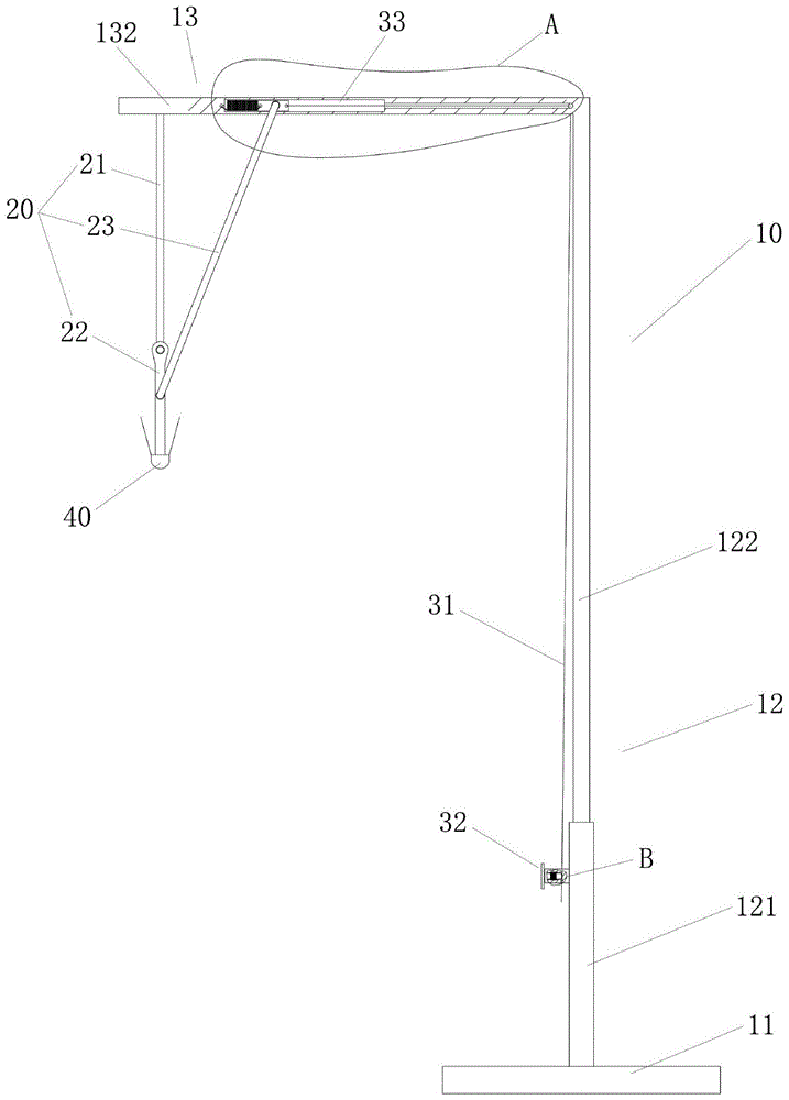
Fig. 1 is a front view of a teaching device for adjusting the falling direction of a badminton ball according to the invention.
Fig. 2 is a right side view of the teaching device for adjusting the falling direction of the shuttlecock.
Fig. 3 is a top view of the teaching device for adjusting the falling direction of the shuttlecock of the present invention.
Fig. 4 is an enlarged cross-sectional view of a portion a of fig. 1.
Fig. 5 is an enlarged cross-sectional view of a portion B in fig. 1.
Fig. 6 is a front view of the teaching device for adjusting the falling direction of the shuttlecock of the present invention in the vertical state of the shuttlecock in the initial state.
Fig. 7 is a front view showing that the teaching device for adjusting the falling direction of the badminton disclosed by the invention adjusts the falling direction of the badminton.
Detailed Description
With reference to fig. 1 to 3, the teaching device for adjusting the falling direction of the shuttlecocks of the present invention comprises a support assembly 10, an angle adjusting assembly 20 and a driving assembly, wherein the angle adjusting assembly 20 is combined with the support assembly 10, the angle adjusting assembly 20 is connected with a shuttlecock 40, the driving assembly is combined with the support assembly 10 and the angle adjusting assembly 20, and the driving assembly can act on the angle adjusting assembly 20 by operating the driving assembly, so as to change the falling direction of the shuttlecock 40.
The support assembly 10 includes a base 11, a telescopic bracket 12 and an upper bracket 13, the telescopic bracket 12 is mounted on the base 11 perpendicular to the horizontal plane, and the upper bracket 13 is mounted on the top end of the telescopic bracket 12. Specifically, the telescopic bracket 12 includes a fixed rod 121 and a movable rod 122, the fixed rod 121 is mounted on the base 11 perpendicular to the horizontal plane, the movable rod 122 is slidably connected to the fixed rod 121, the movable rod 122 slides along the direction perpendicular to the horizontal plane, and the movable rod 122 is adjustable to be fixed. The upper bracket 13 is installed at one end of the moving rod 122 far away from the fixed rod 121. The upper bracket 13 is an L-shaped bracket, and includes a first rod 131 and a second rod 132, the ends of the first rod 131 and the second rod 132 are connected, the first rod 131 and the second rod 132 are perpendicular to each other, and the first rod 131 and the second rod 132 are parallel to a horizontal plane. One end of the first rod 131 is connected to the second rod 132, the other end of the first rod is connected to the top of the moving rod 122, the angle adjusting assembly 20 is connected to the second rod 132, and the angle adjusting assembly 20 is located on the downward surface of the second rod 132. The driving assembly is coupled to the fixed bar 121, the first bar 131, and the second bar 132. The height of the angle adjuster assembly 20 can be adjusted by adjusting the length of the telescopic bracket 12 to adapt to users of different heights.
The angle adjustment assembly 20 includes a fixing rod 21, a connecting rod 22 and a driving rod 23. The end of the fixing rod 21 perpendicular to the horizontal plane and far away from the first rod 131 of the second rod 132 is fixedly connected; the end part of the fixed rod 21 far away from the second rod 132 is connected with the connecting rod 22, one end of the connecting rod 22 is rotatably connected with the fixed rod 21, and the other end of the connecting rod 22 is connected with the bottom of the badminton ball 40; one end of the transmission rod 23 is rotatably connected with the middle of the connecting rod 22, the other end of the transmission rod is connected with the driving assembly, the transmission rod 23 and one end connected with the driving assembly can move back and forth along the second rod 132, and then the connecting rod 22 is driven to rotate in a circular mode through the connecting point of the connecting rod 22 and the fixing rod 21, and the falling angle of the shuttlecock 40 is changed.
As can be seen from fig. 4 and 5, the driving assembly includes a rope 31, a pull rod assembly 32 and a sliding assembly 33, the pull rod assembly 32 and the sliding assembly 33 are connected by the rope 31, two ends of the rope 31 respectively pass through the pull rod assembly 32 and the sliding assembly 33, the pull rod assembly 32 is fixedly connected with the fixed rod 121, the sliding assembly 33 is combined with the upper bracket 13, and the transmission rod 23 is rotatably connected with the sliding assembly 33. Through the operation rope 31 with pull rod assembly 32 can pass through slide assembly 33 acts on transfer line 23, drive transfer line 23 with the one end that slide assembly 33 is connected is followed the second pole motion, and then drives connecting rod 22 rotates, the drive badminton 40 fall to the angle and produce the change.
Specifically, the pull rod assembly 32 includes a pull rod housing 321 and a pull rod 322, the pull rod housing 321 is fixedly connected to the side wall of the fixed rod 121, the pull rod 322 is inserted into the pull rod housing 321, the pull rod 322 is slidably connected to the pull rod housing 321, and the sliding direction of the pull rod 322 is parallel to the horizontal plane. The rope 31 passes through the pull rod shell 321, and the pull rod 322 presses and fixes the rope 31 inside the pull rod shell 321, so that the rope 31 is prevented from sliding. When the pull rod 322 is pulled in a direction away from the fixed rod 121, the pull rod 322 no longer limits the position of the rope 31, and the rope 31 can slide. Furthermore, the inside of the rod casing 321 has a rod cavity 3211, the portion of the rod 322 extending into the inside of the rod casing 321 is located in the rod cavity 3211, and a tension spring 3221 is disposed around the portion of the rod 322 located in the rod cavity 3211. The tension spring 3221 acts on the pull rod 322 through its elastic force, so that the pull rod 322 presses the rope 31, and when the pull rod 322 is pulled in a direction away from the fixed rod 121, the tension spring 3221 is pressed, and after the pull rod 322 is released, the pull rod 322 moves in the direction of the fixed rod 121 under the driving of the tension spring 3221, and presses the rope 31 again.
The sliding assembly 33 includes a sliding slot 331, a sliding block 332, a force-reducing spring 333, a cable hole 334, and a plurality of cable holders 335. The sliding groove 331 and the rope hole 334 are both located inside the second rod 132, and the sliding groove 331 communicates with the rope hole 224. The rope hole 334 is located at an end of the second rod 132 close to the first rod 131, and extends along the second rod 132 in a direction away from the first rod 131, and the sliding groove 331 is located at an end of the rope hole 334 away from the first rod 131. The slider 332 is slidably disposed in the sliding groove 331, the slider 332 slides along the second rod 132, the slider 332 is connected to one end of the sliding groove 331 away from the first rod 131 through the retraction spring 333, and the retraction spring 33 is extended when the slider 332 slides in the direction of the first rod 131. One end of the transmission rod 23 is rotatably connected with the sliding block 332. A plurality of rope holders 335 are coaxially disposed at the side of the first pole 131. The rope 31 passes through the rope frames 335 and the rope holes 334 in sequence to reach the sliding groove 331, and is connected with one end of the sliding block 332 far away from the force-reducing spring 333. By pulling the rope 31, the sliding block 332 slides along the sliding groove 331 towards the first rod 131, the compression spring 333 is stretched, and the end of the transmission rod 23 connected with the sliding block 332 is driven to move towards the first rod 131, so as to drive the connection rod 22 to rotate, and the falling angle of the badminton ball 40 is driven to change. When the rope 31 is not pulled any more, the force-reducing spring 333 is reduced to drive the sliding block 332 to slide in a direction away from the first rod 131 until the sliding block 332 returns to the initial position, and the shuttlecock 40 also returns to the initial vertical state.
As shown in fig. 6 and 7, the teaching device for teaching the adjustable badminton falling direction is in an initial state, the badminton 40 is in a vertical state, and the teaching device can be used for explaining and training the hitting of a vertical ball. In order to change the falling direction of the shuttlecock 40, the pull rod 322 is pulled away from the fixed rod 121,Releasing the rope 31, pulling the rope 31 to drive the sliding block 332 to move, further driving the shuttlecock 40 to change the falling direction through the rotation of the transmission rod 23 and the connecting rod 22, releasing the pull rod 322 after adjusting to an ideal angle, returning the pull rod 322 under the action of the tension spring 3221 to fix the rope 31, further fixing the falling direction of the shuttlecock 40, and at the moment, the contracting force bombSpring 333 is in tension. When the badminton shuttlecock 40 is hit by the racket 50 during training, if enough force is applied, the pressing force of the pull rod 322 on the rope 31 can be overcome, so that the rope 31 can slide again, the sliding block 332 returns to the original position under the action of the force-reducing spring 333, and the badminton shuttlecock 40 also returns to the vertical state again. By replacing the tension spring 3221, the pressing force of the tension rod 322 on the cord 31 can be changed to adapt to different hitting power requirements.
The previous description of the disclosed embodiments is provided to enable any person skilled in the art to make or use the present invention. Various modifications to these embodiments will be readily apparent to those skilled in the art, and the generic principles defined herein may be applied to other embodiments without departing from the spirit or scope of the invention. Thus, the present invention is not intended to be limited to the embodiments shown herein but is to be accorded the widest scope consistent with the principles and novel features disclosed herein.