CN110258569B - Concrete water seepage treatment external sealing back pressure grouting device and grouting method - Google Patents
Concrete water seepage treatment external sealing back pressure grouting device and grouting method Download PDFInfo
- Publication number
- CN110258569B CN110258569B CN201910540672.4A CN201910540672A CN110258569B CN 110258569 B CN110258569 B CN 110258569B CN 201910540672 A CN201910540672 A CN 201910540672A CN 110258569 B CN110258569 B CN 110258569B
- Authority
- CN
- China
- Prior art keywords
- grouting
- sealing
- steel plate
- concrete
- nozzle
- Prior art date
- Legal status (The legal status is an assumption and is not a legal conclusion. Google has not performed a legal analysis and makes no representation as to the accuracy of the status listed.)
- Active
Links
Images


Classifications
-
- E—FIXED CONSTRUCTIONS
- E02—HYDRAULIC ENGINEERING; FOUNDATIONS; SOIL SHIFTING
- E02D—FOUNDATIONS; EXCAVATIONS; EMBANKMENTS; UNDERGROUND OR UNDERWATER STRUCTURES
- E02D15/00—Handling building or like materials for hydraulic engineering or foundations
- E02D15/02—Handling of bulk concrete specially for foundation or hydraulic engineering purposes
-
- E—FIXED CONSTRUCTIONS
- E02—HYDRAULIC ENGINEERING; FOUNDATIONS; SOIL SHIFTING
- E02D—FOUNDATIONS; EXCAVATIONS; EMBANKMENTS; UNDERGROUND OR UNDERWATER STRUCTURES
- E02D29/00—Independent underground or underwater structures; Retaining walls
- E02D29/04—Making large underground spaces, e.g. for underground plants, e.g. stations of underground railways; Construction or layout thereof
-
- E—FIXED CONSTRUCTIONS
- E02—HYDRAULIC ENGINEERING; FOUNDATIONS; SOIL SHIFTING
- E02D—FOUNDATIONS; EXCAVATIONS; EMBANKMENTS; UNDERGROUND OR UNDERWATER STRUCTURES
- E02D31/00—Protective arrangements for foundations or foundation structures; Ground foundation measures for protecting the soil or the subsoil water, e.g. preventing or counteracting oil pollution
- E02D31/02—Protective arrangements for foundations or foundation structures; Ground foundation measures for protecting the soil or the subsoil water, e.g. preventing or counteracting oil pollution against ground humidity or ground water
-
- E—FIXED CONSTRUCTIONS
- E21—EARTH DRILLING; MINING
- E21D—SHAFTS; TUNNELS; GALLERIES; LARGE UNDERGROUND CHAMBERS
- E21D11/00—Lining tunnels, galleries or other underground cavities, e.g. large underground chambers; Linings therefor; Making such linings in situ, e.g. by assembling
- E21D11/04—Lining with building materials
- E21D11/10—Lining with building materials with concrete cast in situ; Shuttering also lost shutterings, e.g. made of blocks, of metal plates or other equipment adapted therefor
- E21D11/105—Transport or application of concrete specially adapted for the lining of tunnels or galleries ; Backfilling the space between main building element and the surrounding rock, e.g. with concrete
-
- E—FIXED CONSTRUCTIONS
- E21—EARTH DRILLING; MINING
- E21D—SHAFTS; TUNNELS; GALLERIES; LARGE UNDERGROUND CHAMBERS
- E21D11/00—Lining tunnels, galleries or other underground cavities, e.g. large underground chambers; Linings therefor; Making such linings in situ, e.g. by assembling
- E21D11/38—Waterproofing; Heat insulating; Soundproofing; Electric insulating
-
- E—FIXED CONSTRUCTIONS
- E02—HYDRAULIC ENGINEERING; FOUNDATIONS; SOIL SHIFTING
- E02D—FOUNDATIONS; EXCAVATIONS; EMBANKMENTS; UNDERGROUND OR UNDERWATER STRUCTURES
- E02D2250/00—Production methods
- E02D2250/003—Injection of material
Abstract
The device comprises an outer sealing steel plate, a compressed air nozzle, a grouting nozzle, an elastic sealing strip, a pressing fastener and a pressing fastener, wherein when the device is used for carrying out concrete seepage treatment, a single piece or a plurality of pieces of the outer sealing steel plate with the periphery adhered with the elastic sealing strip are sealed on the concrete seepage surface by adopting expansion bolts, so that the totally-closed back pressure grouting treatment on the concrete seepage appearance can be realized, the grouting adopts epoxy slurry with good permeability and high early setting strength, and a compressed air and compressed slurry mixed grouting process is implemented through the compressed air nozzle and the grouting nozzle arranged on the outer sealing steel plate, so that the concrete seepage can be effectively filled, permeated and solidified from outside to inside, and the double effects of water-proofing, leakage stoppage and structural repair on the concrete structure seepage defect are achieved.
Description
Technical Field
The invention belongs to the technical field of building construction, and particularly relates to an external sealing back pressure grouting device and a grouting method for concrete water seepage treatment.
Background
The waterproof effect of the concrete for the underground engineering is one of important quality indexes for measuring the underground engineering, is directly related to the corrosion and the aging of underground engineering equipment and structures, and influences the operation environment and the service life of the underground engineering. However, it is a normal state that different degrees of water leakage of underground engineering concrete occurs due to defects in the construction quality of concrete, design defects of waterproof structures, and the like.
In the prior art, the treatment of the water leakage of the concrete structure defects mainly adopts the technical treatment of cement slurry or chemical slurry grouting, and the traditional drilling pipe burying and caulking closed grouting process technology is continuously used, the prior art is only effective on the water leakage of concrete construction joints, contact joints, structural joints and wide cracks, and is difficult to implement on the large-area water leakage caused by concrete honeycomb pitted surface, temperature cracks and the like.
Disclosure of Invention
The embodiment of the invention provides an external sealing back pressure grouting device for water seepage treatment of concrete, and solves the problem that large-area water seepage caused by concrete honeycomb pitted surface, temperature cracks and the like is difficult to implement in the prior art by using the traditional drilling pipe burying and caulking sealing grouting process technology.
An external sealing back pressure grouting device for concrete water seepage treatment comprises an external sealing steel plate, a pressure blast nozzle, a grouting nozzle, an elastic sealing strip, a pressure pasting fastener and a pressure sealing fastener;
the air pressing nozzle and the grouting nozzle are arranged at the central part of the outer sealing steel plate;
the press seal fastener is arranged on the peripheral edge of the outer seal steel plate;
the elastic sealing strip is adhered to the periphery of the outer sealing steel plate and close to the inner side of the press-sealing fastener;
the pressing fasteners are uniformly distributed in the middle of the outer sealing steel plate;
the outer seal steel plate is pressed and pasted on the concrete seepage surface through the pressing and pasting fastener, and the elastic sealing strips pasted on the periphery of the outer seal steel plate are pressed and sealed on the concrete surface through the pressing and pasting fastener.
Preferably, the outer sealing steel plate is a high-strength elastic steel plate with the thickness of less than 3 mm.
Further preferably, the outer sealing steel plate is a stainless steel elastic steel plate with the thickness of 1.5-2.0 mm.
Preferably, the outer sealing steel plate is provided with holes for mounting the press-fit fasteners and the press-seal fasteners.
Further preferably, the outer sealing steel plate is further provided with a spare hole for installing a press sealing fastener.
The spare hole of the press seal fastener is used for locally reinforcing press seal when the external seal effect of the external seal steel plate is locally unsealed.
Preferably, the width of the elastic sealing strip is not less than 5mm, and the thickness of the elastic sealing strip is not less than 2 mm.
Further preferably, the elastic sealing strip is a TPE elastic sealing strip with the width of 8-10 mm and the thickness of 3-5 mm.
Preferably, the pressure tuyere hollow and the outer steel plate outer sealing cavity are communicated, the pressure tuyere comprises a pressure tuyere seat, a pressure tuyere check valve and a pressure tuyere connecting nozzle which are sequentially connected, and the base surface of the pressure tuyere seat and the outer steel plate are aligned and communicated with an eyelet formed in the outer sealing cavity in a welded connection mode.
Preferably, grout mouth cavity with the outer cavity that seals of steel sheet is linked together, grout mouth is including consecutive grout mouth seat, manometer tee bend, drainage gate valve, gate valve tee bend, grout check valve and grout connector nozzle, grout mouth seat base face and the outer steel sheet of sealing aim at the eyelet welded connection who communicates in the outer cavity of sealing and open.
Preferably, the pressing fastener comprises a pressing expansion bolt, a pressing gasket and a pressing rubber ring, wherein the thread specification of the pressing expansion bolt is not less than M6mm, and the nominal length of the pressing expansion bolt is not less than 80 mm.
Preferably, the pressure seal fastener comprises a pressure seal expansion bolt and a pressure seal gasket, wherein the thread specification of the pressure seal expansion bolt is not less than M6mm, and the nominal length of the pressure seal expansion bolt is not less than 80 mm.
The method for carrying out the external sealing back pressure grouting by the external sealing back pressure grouting device for the concrete water seepage treatment comprises the following steps:
s1, processing an outer sealing steel plate, welding a compressed air nozzle and a grouting nozzle, sticking an elastic sealing strip to form an outer sealing steel plate assembly, and coating a layer of stripping agent on the joint surface of the outer sealing steel plate assembly and the concrete;
s2 concrete seepage surface cleaning and marking, and performing combined layout design of an external sealing back pressure grouting device according to the concrete seepage surface treatment range;
s3, sequentially installing each outer sealing steel plate assembly according to the following procedures:
drilling mounting holes of the press-fit fastener and the press-seal fastener according to the arrangement requirement, then mounting an expansion bolt, mounting an outer seal steel plate assembly, and finally screwing an expansion bolt nut to seal the outer seal steel plate assembly on the surface of the concrete;
s4, connecting all blast nozzles to a blast supply pipe in parallel by adopting a blast rubber pipe, and connecting all grouting nozzles to a grouting supply pipe in parallel by adopting a grouting rubber pipe;
s5, closing the drainage gate valve, directly checking the external sealing seepage surface through the compressed air main pipe, and stopping compressed air to observe the seepage pressure value of the pressure gauge after confirming the combined external sealing effect of the external sealing back pressure grouting device;
s6, opening the drainage gate valve, simultaneously pressing air on the concrete seepage surface through the compressed air supply pipe, closing all the drainage gate valves one by one when the drainage gate valves discharge clean air, and controlling the seepage surface to be compressed according to the set effective air pressure after the seepage pressure is subtracted;
s7, reversely pouring high-permeability quick-setting epoxy grout on the water seepage surface of the concrete through a grouting grout supply pipe, controlling the grouting injection rate to be less than 0.1L/min, controlling the pressure to be unchanged, continuously shielding grout for more than 30min until the grouting pressure reaches the effective pressure set after the water seepage pressure is subtracted, and stopping mixing compressed air and grouting;
s8, removing all the combined air pipes and grout pipes and cleaning epoxy grouting pipelines and equipment;
s9, after the concrete is solidified for more than 60min, all expansion bolts and nuts are screwed off, the external sealing back pressure grouting device assembly is disassembled, the external leaking expansion screw is cut, grouting epoxy of the external protruding gel is removed, and the treated concrete seepage surface is trimmed.
The concrete seepage treatment external sealing back pressure grouting device provided by the embodiment of the invention can be widely applied to the seepage treatment of concrete structures of underground engineering such as urban subways, basement buildings, hydropower underground powerhouses, traffic tunnels and the like, and has the advantages of wide application range and good treatment effect.
Compared with the prior art, the invention has the beneficial effects that: the existing leakage treatment technology for the defects of the underground engineering concrete structure is only suitable for the leakage treatment which is apparently in the character of point leakage or line leakage, and the effective sealing and grouting treatment is difficult to implement for the leakage which is apparently in the character of surface leakage. The outer sealing back pressure grouting device for the concrete water seepage treatment of the embodiment of the invention adopts expansion bolts to seal a single piece or a plurality of pieces of outer sealing steel plates with elastic sealing strips adhered around on the surface of the concrete water seepage, can realize the totally closed back pressure grouting treatment of the concrete water seepage appearance, adopts epoxy grout with good permeability and quick setting and early strength for grouting, and implements a compressed air and compressed grout mixed grouting process through a compressed air nozzle and a grouting nozzle arranged on the outer sealing steel plates, can effectively fill, permeate and solidify the concrete water seepage from outside to inside, and achieves the double effects of water-proofing, leakage stoppage and structural repair on the concrete structure seepage defects.
Drawings
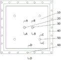
FIG. 1 is a schematic reverse view of the concrete infiltration treatment apparatus of example 1.
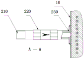
Fig. 2 is a schematic sectional view of the wind-pressing mechanism in the direction of a-a.
FIG. 3 is a schematic sectional view of the grouting mechanism in the direction B-B.
FIG. 4 is a schematic cross-sectional view of the first fastener in the direction C-C.
FIG. 5 is a schematic cross-sectional view of a second fastener in the direction D-D.
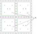
Fig. 6 is a schematic diagram of the combined splicing and use of the external sealing back pressure grouting device.
Detailed Description
The embodiment of the invention provides an external sealing back pressure grouting device and a grouting method for concrete water seepage treatment, and solves the technical problem that the traditional drilling pipe burying and caulking closed grouting process technology is difficult to implement for large-area water seepage caused by concrete honeycomb pitted surface, temperature cracks and the like in the prior art.
In order to better understand the above technical solutions, the above technical solutions will be described in detail with reference to specific embodiments.
Example 1
An external sealing back pressure grouting device for concrete water seepage treatment, as shown in figure 1, comprises an external sealing steel plate 10, a pressure air nozzle 20, a grouting nozzle 30, an elastic sealing strip 40, a pressure attaching fastener 50 and a pressure sealing fastener 60;
the pressure air nozzle 20 and the grouting nozzle 30 are arranged at the central part of the outer sealing steel plate 10;
the press seal fasteners 60 are arranged on the peripheral edge of the outer seal steel plate 10;
the elastic sealing strip 40 is adhered to the periphery of the outer sealing steel plate 10 and close to the inner side of the press-sealing fastener 60;
the pressing fasteners 50 are uniformly distributed in the middle of the outer sealing steel plate 10;
the outer seal steel plate 10 is pressed and pasted on the concrete seepage surface through the pressing and pasting fastener 50, and the elastic sealing strips 40 pasted on the periphery of the outer seal steel plate 10 are pressed and sealed on the concrete surface through the pressing and pasting fastener 60.
The outer sealing steel plate 10 is a high-strength elastic steel plate with the thickness smaller than 3mm, preferably a stainless steel elastic steel plate with the thickness of 1.5-2.0 mm, holes for mounting the pressing and sticking fasteners 50 and the pressing and sealing fasteners 60 are formed in the outer sealing steel plate 10, expansion bolts are mounted on only part of the holes for mounting the pressing and sealing fasteners 60 in actual mounting, and other holes are spare holes for local reinforcing pressing and sealing when local unsealing occurs in the outer sealing effect of the outer sealing steel plate.
The width of elastic sealing strip 40 is not less than 5mm, and thickness is not less than 2mm, and the preferred width of elastic sealing strip 40 is 8 ~ 10mm, and thickness is 3 ~ 5 mm's TPE elastic sealing strip.
As shown in fig. 2, the hollow of the air pressing nozzle 20 is communicated with the outer sealing cavity of the outer sealing steel plate 10, the air pressing nozzle 20 comprises an air pressing nozzle seat 230, an air pressing nozzle check valve 220 and an air pressing connection nozzle 210 which are connected in sequence, and the base surface of the air pressing nozzle seat 230 is aligned with the outer sealing steel plate 10 and is communicated with the eyelet opened in the outer sealing cavity in a welding manner.
As shown in fig. 3, the hollow of the grouting nozzle 30 is communicated with the outer sealed cavity of the outer sealed steel plate 10, the grouting nozzle 30 comprises a grouting nozzle seat 350, a pressure gauge 340, a pressure gauge tee 360, a drain gate valve 330, a gate valve tee 370, a grouting check valve 320 and a grouting connection nozzle 310 which are sequentially connected, and the base surface of the grouting nozzle seat 350 is aligned with the outer sealed steel plate 10 and is communicated with the eyelet formed in the outer sealed cavity in a welded manner.
A cross-sectional view of the pressing fastener 50 is shown in fig. 4, the pressing fastener 50 includes a pressing expansion bolt 510, a pressing washer 520 and a pressing rubber ring 530, and the thread specification of the pressing expansion bolt 510 is not less than M6mm, and the nominal length is not less than 80 mm.
The cross-sectional view of the press seal fastener 60 is shown in fig. 5, the press seal fastener 60 comprises a press seal expansion bolt 610 and a press seal gasket 620, the thread specification of the press seal expansion bolt 610 is not less than M6mm, and the nominal length is not less than 80 mm.
In the concrete water seepage treatment external sealing back pressure grouting device, the size and the shape of the external sealing steel plate 10 can be designed and processed according to the size of a water seepage surface, in practical application, the external sealing steel plate 10 is usually processed into a square standard part, and the square design considers that joint sealing is convenient when a plurality of external sealing steel plates are overlapped, as shown in fig. 6.
Example 2
The embodiment provides a method for carrying out back pressure grouting by an external sealing back pressure grouting device for concrete water seepage treatment, which comprises the following steps:
s1, processing an outer sealing steel plate 10, welding the air pressing nozzle 20 and the grouting nozzle 30, sticking an elastic sealing strip 40 to form an outer sealing steel plate assembly, and coating a layer of stripping agent on the joint surface of the outer sealing steel plate assembly and the concrete;
s2 concrete seepage surface cleaning and marking, and performing combined layout design of an external sealing back pressure grouting device according to the concrete seepage surface treatment range;
s3, sequentially installing each outer sealing steel plate assembly according to the following procedures:
drilling mounting holes of the press-fit fastener 50 and the press-seal fastener 60 according to arrangement requirements, mounting expansion bolts, mounting an outer seal steel plate assembly, and finally screwing expansion bolt nuts to seal the outer seal steel plate assembly on the surface of concrete;
s4, connecting all the blast nozzles 20 to the blast main pipe in parallel by adopting a blast rubber pipe, and connecting all the grouting nozzles 30 to the grouting main pipe in parallel by adopting a grouting rubber pipe;
s5, closing the drainage gate valve 330, directly checking the external sealing seepage surface pressure wind through the pressure wind main pipe and confirming the combined external sealing effect of the external sealing back pressure grouting device, and stopping the pressure wind to observe the seepage pressure value of the pressure gauge 340; .
S6, opening the drainage gate valve 330, simultaneously pressing air on the concrete seepage surface through the compressed air main pipe, closing all the drainage gate valves 330 one by one when the drainage gate valve 330 discharges clean air, and controlling the seepage surface to be pressed according to the set effective air pressure after the seepage pressure is subtracted;
s7, grouting high-permeability quick-setting epoxy grout on the water seepage surface of the concrete through the main grouting pipe in a back-pressure manner, controlling the grouting injection rate to be smaller than 0.1L/min, keeping the grouting pressure unchanged until the grouting pressure reaches the effective pressure set after the water seepage pressure is subtracted, continuously shielding the grout for more than 30min, and stopping mixing compressed air and grouting;
s8, removing all the combined air pipes and grout pipes and cleaning epoxy grouting pipelines and equipment;
s9, after the concrete is solidified for more than 60min, all expansion bolts and nuts are screwed off, the external sealing back pressure grouting device assembly is disassembled, the external leaking expansion screw is cut, grouting epoxy of the external protruding gel is removed, and the treated concrete seepage surface is trimmed.
Claims (7)
1. An external sealing back pressure grouting device for concrete water seepage treatment is characterized by comprising an external sealing steel plate (10), a pressure air nozzle (20), a grouting nozzle (30), an elastic sealing strip (40), a pressure attaching fastener (50) and a pressure sealing fastener (60);
the air compression nozzle (20) and the grouting nozzle (30) are arranged at the central part of the outer sealing steel plate (10);
the elastic sealing strip (40) is adhered to the periphery of the outer sealing steel plate (10) and close to the inner side of the press sealing fastener (60);
the pressing fasteners (50) are uniformly distributed in the middle of the outer sealing steel plate (10);
the press seal fastening piece (60) is arranged on the peripheral edge of the outer seal steel plate (10);
the outer sealing steel plate (10) is pressed and attached to the concrete seepage surface through the pressing and attaching fastener (50), and the elastic sealing strips (40) attached to the periphery of the outer sealing steel plate (10) are pressed and sealed on the concrete surface through the pressing and sealing fastener (60);
the outer sealing steel plate (10) is a high-strength elastic steel plate with the thickness less than 3 mm;
the outer seal steel plate (10) is provided with a first hole for installing the pressing and pasting fastener (50) and the pressing and sealing fastener (60), and the outer seal steel plate (10) is further provided with a second hole for communicating the pressure air nozzle (20) and the grouting nozzle (30) with an outer seal cavity.
2. The concrete water seepage treatment external sealing back pressure grouting device according to claim 1, characterized in that the width of the elastic sealing strip (40) is not less than 5mm, and the thickness is not less than 2 mm.
3. The concrete infiltration treatment outer sealing back pressure grouting device according to claim 1, characterized in that the air pressing nozzle (20) is hollow and communicated with the outer sealing cavity of the outer sealing steel plate (10), the air pressing nozzle (20) comprises an air pressing nozzle seat (230), an air pressing nozzle check valve (220) and an air pressing connecting nozzle (210) which are sequentially connected, and the base surface of the air pressing nozzle seat (230) is aligned with the outer sealing steel plate (10) and communicated with the eyelet welding connection opened by the outer sealing cavity.
4. The concrete infiltration treatment external sealing back pressure grouting device of claim 1, wherein the grouting nozzle (30) is hollow and is communicated with the external sealing steel plate (10) external sealing cavity, the grouting nozzle (30) comprises a grouting nozzle seat (350), a pressure gauge (340), a pressure gauge tee joint (360), a drainage gate valve (330), a gate valve tee joint (370), a grouting check valve (320) and a grouting connection nozzle (310) which are sequentially connected, and the base surface of the grouting nozzle seat (350) is aligned with the external sealing steel plate (10) and is communicated with the open hole welded connection of the external sealing cavity.
5. The concrete water seepage treatment external sealing back pressure grouting device according to claim 1, wherein the pressing fastening piece (50) comprises a pressing expansion bolt (510), a pressing gasket (520) and a pressing rubber ring (530), and the thread specification of the pressing expansion bolt (510) is not less than M6mm, and the nominal length is not less than 80 mm.
6. The concrete water seepage treatment external sealing back pressure grouting device according to claim 1, characterized in that the pressure sealing fasteners (60) comprise pressure sealing expansion bolts (610) and pressure sealing gaskets (620), and the thread specifications of the pressure sealing expansion bolts (610) are not less than M6mm and the nominal length is not less than 80 mm.
7. The method for carrying out the external sealing and back pressure grouting by the external sealing and back pressure grouting device for the water seepage treatment of the concrete according to any one of claims 1 to 6, is characterized by comprising the following steps:
s1, processing an outer sealing steel plate, welding a compressed air nozzle and a grouting nozzle, sticking an elastic sealing strip to form an outer sealing steel plate assembly, and coating a layer of stripping agent on the joint surface of the outer sealing steel plate assembly and the concrete;
s2 concrete seepage surface cleaning and marking, and performing combined layout design of an external sealing back pressure grouting device according to the concrete seepage surface treatment range;
s3, sequentially installing each outer sealing steel plate assembly according to the following procedures:
drilling mounting holes of the press-fit fastener and the press-seal fastener according to the arrangement requirement, then mounting an expansion bolt, mounting an outer seal steel plate assembly, and finally screwing an expansion bolt nut to seal the outer seal steel plate assembly on the surface of the concrete;
s4, connecting all blast nozzles to a blast supply pipe in parallel by adopting a blast rubber pipe, and connecting all grouting nozzles to a grouting supply pipe in parallel by adopting a grouting rubber pipe;
s5, closing the drainage gate valve, directly checking the external sealing seepage surface through the compressed air main pipe, and stopping compressed air to observe the seepage pressure value of the pressure gauge after confirming the combined external sealing effect of the external sealing back pressure grouting device;
s6, opening the drainage gate valve, simultaneously pressing air on the concrete seepage surface through the compressed air supply pipe, closing all the drainage gate valves one by one when the drainage gate valves discharge clean air, and controlling the seepage surface to be compressed according to the set effective air pressure after the seepage pressure is subtracted;
s7, reversely pouring high-permeability quick-setting epoxy grout on the water seepage surface of the concrete through a grouting grout supply pipe, controlling the grouting injection rate according to the grouting injection rate of less than 0.1L/min until the grouting pressure reaches the effective pressure set after the water seepage pressure is subtracted, controlling the pressure to be unchanged, continuously shielding grout for more than 30min, and stopping mixed air compression and grouting;
s8, removing all the combined air pipes and grout pipes and cleaning epoxy grouting pipelines and equipment;
s9, after the concrete is solidified for more than 60min, all expansion bolts and nuts are screwed off, the external sealing back pressure grouting device assembly is disassembled, the external leaking expansion screw is cut, grouting epoxy of the external protruding gel is removed, and the treated concrete seepage surface is trimmed.
Priority Applications (1)
| Application Number | Priority Date | Filing Date | Title |
|---|---|---|---|
| CN201910540672.4A CN110258569B (en) | 2019-06-21 | 2019-06-21 | Concrete water seepage treatment external sealing back pressure grouting device and grouting method |
Applications Claiming Priority (1)
| Application Number | Priority Date | Filing Date | Title |
|---|---|---|---|
| CN201910540672.4A CN110258569B (en) | 2019-06-21 | 2019-06-21 | Concrete water seepage treatment external sealing back pressure grouting device and grouting method |
Publications (2)
| Publication Number | Publication Date |
|---|---|
| CN110258569A CN110258569A (en) | 2019-09-20 |
| CN110258569B true CN110258569B (en) | 2021-03-19 |
Family
ID=67920117
Family Applications (1)
| Application Number | Title | Priority Date | Filing Date |
|---|---|---|---|
| CN201910540672.4A Active CN110258569B (en) | 2019-06-21 | 2019-06-21 | Concrete water seepage treatment external sealing back pressure grouting device and grouting method |
Country Status (1)
| Country | Link |
|---|---|
| CN (1) | CN110258569B (en) |
Families Citing this family (1)
| Publication number | Priority date | Publication date | Assignee | Title |
|---|---|---|---|---|
| CN112049233B (en) * | 2020-08-20 | 2021-11-30 | 韶关市新城兴建筑工程有限公司 | Basement terrace seepage water repairing method |
Family Cites Families (5)
| Publication number | Priority date | Publication date | Assignee | Title |
|---|---|---|---|---|
| JP4027817B2 (en) * | 2003-02-20 | 2007-12-26 | 清水建設株式会社 | High pressure injection water stop method and water stop material used therefor |
| CN103161166B (en) * | 2013-03-13 | 2015-02-25 | 长江三峡通航管理局 | Wind-guiding chemical grouting device and grouting method of the same |
| CN104088254B (en) * | 2014-07-11 | 2015-09-30 | 泛华建设集团有限公司 | Pressure-bearing reinforced concrete structure leakage repair device and construction method thereof |
| US9725917B2 (en) * | 2015-05-08 | 2017-08-08 | John Huh | Restorative waterproofing membrane and method of forming the same |
| CN210288398U (en) * | 2019-06-21 | 2020-04-10 | 长沙普照生化科技有限公司 | Concrete infiltration is handled outer back pressure cementer that seals |
-
2019
- 2019-06-21 CN CN201910540672.4A patent/CN110258569B/en active Active
Also Published As
| Publication number | Publication date |
|---|---|
| CN110258569A (en) | 2019-09-20 |
Similar Documents
| Publication | Publication Date | Title |
|---|---|---|
| CN103669292A (en) | Concrete joint water stop structure and construction method thereof | |
| CN110258569B (en) | Concrete water seepage treatment external sealing back pressure grouting device and grouting method | |
| CN210288398U (en) | Concrete infiltration is handled outer back pressure cementer that seals | |
| CN113718969A (en) | Basement outer wall crack waterproof treatment device and crack plugging method | |
| CN108755776A (en) | A kind of underground structure bottom plate leak Integrated Processing Unit and its processing method | |
| CN207608935U (en) | A kind of basement bottom board water seepage treatment device | |
| CN113431377A (en) | Concrete slab crack seepage treatment device and seepage treatment method | |
| CN210919087U (en) | Concrete pipe piece caulking plugging device | |
| CN213330003U (en) | Template for preventing mortar leakage caused by staggering of wall body section pouring and connecting position | |
| CN208455679U (en) | A kind of underground structure bottom plate leak Integrated Processing Unit | |
| CN210712941U (en) | Full-section PC pipe gallery splicing structure | |
| CN108131506A (en) | The construction method that a kind of steel pipe is connect with FRP sand tube | |
| CN209278658U (en) | A kind of municipal administration supplying drainage pipeline connecting structure | |
| CN209873861U (en) | Sealing device for lap joint of steel corrugated plate pipe gallery plates | |
| CN113653511A (en) | Leaking stoppage and grouting method for shield tunnel joint | |
| CN205475371U (en) | Immersed tube tunnel watertight door leak hunting device | |
| CN206358679U (en) | A kind of low pressure vessel leak stopping structure | |
| CN218267677U (en) | Leakage-proof structure for building water supply and drainage engineering | |
| CN206784450U (en) | Caulking type sealing component | |
| CN213897228U (en) | Basement waterproofing steel plate structure | |
| CN219411003U (en) | Hole plugging structure for concrete wall | |
| CN107724339B (en) | Engineering surface layer water stop template structure and construction method thereof | |
| CN210439231U (en) | Steel edge water-stop cover plate for repairing underwater crack | |
| CN220647236U (en) | Leak stopping repair structure of prestressed steel cylinder concrete pipe | |
| CN215673980U (en) | Wall bushing |
Legal Events
| Date | Code | Title | Description |
|---|---|---|---|
| PB01 | Publication | ||
| PB01 | Publication | ||
| SE01 | Entry into force of request for substantive examination | ||
| SE01 | Entry into force of request for substantive examination | ||
| GR01 | Patent grant | ||
| GR01 | Patent grant | ||
| TR01 | Transfer of patent right | ||
| TR01 | Transfer of patent right |
Effective date of registration: 20220318 Address after: 410000 plant 1, plant area of Hunan Longxiang Bus Co., Ltd., No. 258, Shuyuan South Road, Tianxin District, Changsha City, Hunan Province Patentee after: Changsha Puzhao Material Technology Co.,Ltd. Address before: 6 / F, building 7, oak garden, Changsha hi tech Industrial Development Zone, Changsha, Hunan 410000 Patentee before: CHANGSHA PUZHAO BIOCHEMICAL TECHNOLOGY Co.,Ltd. |