CN110144718B - Intelligent cloth marking equipment - Google Patents
Intelligent cloth marking equipment Download PDFInfo
- Publication number
- CN110144718B CN110144718B CN201910548520.9A CN201910548520A CN110144718B CN 110144718 B CN110144718 B CN 110144718B CN 201910548520 A CN201910548520 A CN 201910548520A CN 110144718 B CN110144718 B CN 110144718B
- Authority
- CN
- China
- Prior art keywords
- fixedly connected
- motor
- lifting
- shell
- shaped
- Prior art date
- Legal status (The legal status is an assumption and is not a legal conclusion. Google has not performed a legal analysis and makes no representation as to the accuracy of the status listed.)
- Active
Links
- 239000004744 fabric Substances 0.000 title claims abstract description 61
- 230000007246 mechanism Effects 0.000 claims abstract description 81
- 238000004804 winding Methods 0.000 claims abstract description 25
- 238000011049 filling Methods 0.000 claims abstract description 11
- 238000012856 packing Methods 0.000 claims description 21
- 239000004033 plastic Substances 0.000 claims description 17
- 229920003023 plastic Polymers 0.000 claims description 17
- 238000001179 sorption measurement Methods 0.000 claims description 14
- 238000001125 extrusion Methods 0.000 claims description 10
- 239000000945 filler Substances 0.000 claims description 7
- 230000000903 blocking effect Effects 0.000 claims description 2
- 238000005457 optimization Methods 0.000 description 9
- 239000000463 material Substances 0.000 description 6
- 238000003756 stirring Methods 0.000 description 4
- 239000011248 coating agent Substances 0.000 description 3
- 238000000576 coating method Methods 0.000 description 3
- 238000000034 method Methods 0.000 description 3
- 238000010586 diagram Methods 0.000 description 2
- 230000005611 electricity Effects 0.000 description 2
- 239000003973 paint Substances 0.000 description 2
- 230000003068 static effect Effects 0.000 description 2
- 238000007792 addition Methods 0.000 description 1
- 230000009286 beneficial effect Effects 0.000 description 1
- 238000012986 modification Methods 0.000 description 1
- 230000004048 modification Effects 0.000 description 1
- 238000006467 substitution reaction Methods 0.000 description 1
Images




Classifications
-
- D—TEXTILES; PAPER
- D06—TREATMENT OF TEXTILES OR THE LIKE; LAUNDERING; FLEXIBLE MATERIALS NOT OTHERWISE PROVIDED FOR
- D06G—MECHANICAL OR PRESSURE CLEANING OF CARPETS, RUGS, SACKS, HIDES, OR OTHER SKIN OR TEXTILE ARTICLES OR FABRICS; TURNING INSIDE-OUT FLEXIBLE TUBULAR OR OTHER HOLLOW ARTICLES
- D06G1/00—Beating, brushing, or otherwise mechanically cleaning or pressure cleaning carpets, rugs, sacks, hides, or other skin or textile articles or fabrics
-
- D—TEXTILES; PAPER
- D06—TREATMENT OF TEXTILES OR THE LIKE; LAUNDERING; FLEXIBLE MATERIALS NOT OTHERWISE PROVIDED FOR
- D06H—MARKING, INSPECTING, SEAMING OR SEVERING TEXTILE MATERIALS
- D06H1/00—Marking textile materials; Marking in combination with metering or inspecting
-
- D—TEXTILES; PAPER
- D06—TREATMENT OF TEXTILES OR THE LIKE; LAUNDERING; FLEXIBLE MATERIALS NOT OTHERWISE PROVIDED FOR
- D06H—MARKING, INSPECTING, SEAMING OR SEVERING TEXTILE MATERIALS
- D06H3/00—Inspecting textile materials
- D06H3/08—Inspecting textile materials by photo-electric or television means
Landscapes
- Engineering & Computer Science (AREA)
- Textile Engineering (AREA)
- Chemical & Material Sciences (AREA)
- Materials Engineering (AREA)
- Mechanical Engineering (AREA)
- Treatment Of Fiber Materials (AREA)
- Transmission Devices (AREA)
Abstract
The invention relates to an intelligent robot-related intelligent cloth marking device, in particular to an intelligent cloth marking device which comprises a rotary scrap-reducing mechanism, a device shell, a marking mechanism, a cloth winding and releasing mechanism, a filling mechanism, a lifting baffle mechanism and an intelligent identification mechanism. The rotary scrap falling mechanism is connected with an equipment shell, the equipment shell is connected with the marking mechanism, the lifting baffle plate mechanism is connected with the equipment shell, the equipment shell is connected with the filling mechanism, and the equipment shell is connected with the intelligent identification mechanism.
Description
Technical Field
The invention relates to intelligent robot correlation, in particular to intelligent cloth marking equipment.
Background
In the subsequent processing process of the cloth, the position of the cloth is often required to be marked so as to be convenient for determining the position, and in order to solve the problem, an intelligent cloth marking device is designed to solve the problem.
Disclosure of Invention
The invention mainly solves the technical problem of providing intelligent cloth marking equipment which has the functions of marking, replacing materials and rotating to reduce scraps and adjusting coating strength.
In order to solve the technical problems, the invention relates to an intelligent robot-related intelligent cloth marking device, and particularly relates to an intelligent cloth marking device which comprises a rotary scrap falling mechanism, a device shell, a marking mechanism, a cloth winding and placing mechanism, a filling mechanism, a lifting baffle mechanism and an intelligent identification mechanism. The rotary scrap falling mechanism is connected with an equipment shell, the equipment shell is connected with the marking mechanism, the lifting baffle plate mechanism is connected with the equipment shell, the equipment shell is connected with the filling mechanism, and the equipment shell is connected with the intelligent identification mechanism.
As a further optimization of the technical scheme, the rotary scrap-reducing mechanism of the intelligent cloth marking device comprises a square shell, a rotary power structure, a fan and a motor, a bar-shaped fixing plate, a grid plate and an impact and adsorption structure, wherein the square shell is connected with the rotary power structure, the square shell is fixedly connected with the bar-shaped fixing plate, the bar-shaped fixing plate is fixedly connected with the fan and the motor, the fan and the motor are matched with the square shell through holes, the square shell is fixedly connected with the grid plate, the grid plate is connected with the impact and adsorption structure, and the impact and adsorption structure is connected with the square shell; a T-shaped side groove is formed in the square shell; the rotary power structure comprises a positioning block, a central short shaft, a central gear, a motor for rotation and a gear for rotation, wherein the positioning block is fixedly connected with the square shell, the positioning block is movably connected with the central short shaft through a through hole, the central short shaft is fixedly connected with the central gear through the through hole, the central gear is meshed with the gear for rotation, the gear for rotation is fixedly connected with the motor for rotation, and the motor for rotation is fixedly connected with the positioning block; striking and adsorption structure include the striking piece, the cam motor, supporting spring, the plastics graticule, the belt, the power shaft, the striking piece passes through T shape side slot swing joint with square shell, cam and cam motor fixed connection, the cam motor passes through recess fixed connection with square shell, striking piece and supporting spring fixed connection, supporting spring and plastics graticule fixed connection, plastics graticule and square shell fixed connection, the plastics graticule is connected with the belt contact, the belt is connected with the power shaft, the power shaft is connected with square shell.
As a further optimization of the technical scheme, the equipment shell of the intelligent cloth marking equipment is provided with a motor fixing groove, a semicircular groove, a lifting T-shaped groove, a stepped threaded groove, a circular groove, a short T-shaped groove, a first hinge hole and a second hinge hole.
As further optimization of the technical scheme, the marking mechanism of the intelligent cloth marking device comprises a half-tooth motor, a half gear, a swinging square block, an L-shaped block and a bottom spring, the H-shaped connecting piece, promote articulated piece, the mark push pedal, the mark flitch, bottom spring and equipment shell fixed connection, bottom spring and L-shaped piece fixed connection, L-shaped piece and swing square fixed connection, the swing square is articulated mutually with H-shaped connecting piece, half-tooth motor and equipment shell fixed connection, half-tooth motor and half-gear fixed connection, half-gear meshes with L-shaped piece mutually, H-shaped connecting piece and equipment shell pass through hinge hole two-phase hinge, H-shaped connecting piece is articulated mutually with the articulated piece of promotion, it is articulated mutually with the mark push pedal to promote articulated piece, the mark push pedal is articulated mutually through hinge hole one with equipment shell, the mark push pedal passes through recess gap connection with the mark flitch.
As a further optimization of the technical scheme, the cloth winding and releasing mechanism of the intelligent cloth marking device comprises a bottom fixing plate, a motor for winding and releasing and a cloth shaft, wherein the bottom fixing plate is fixedly connected with an equipment shell, the equipment shell is fixedly connected with the fixing plate, the motor for winding and releasing is fixedly connected with the bottom fixing plate, the motor for winding and releasing is fixedly connected with the cloth shaft, and the cloth shaft is in clearance connection with the fixing plate through a through hole.
As a further optimization of the technical scheme, the packing mechanism of the intelligent cloth marking device comprises a T-shaped supporting foot, a packing push plate, a packing block, a small swinging piece, a swinging rod, a central shaft, an extrusion pushing piece, an adjusting spring, an adjusting threaded piece, a motor for shifting and a shifting cam, wherein the adjusting threaded piece is in contact connection with the adjusting spring, the adjusting spring is in contact connection with the extrusion pushing piece, the adjusting spring and the adjusting threaded piece are all positioned in a stepped threaded groove, the extrusion pushing piece is in contact connection with the swinging rod, the swinging rod is fixedly connected with the central shaft, the central shaft is in gap connection with a device shell through a circular groove, the motor for shifting is fixedly connected with the device shell, the motor for shifting is fixedly connected with the shifting cam, the swinging rod is hinged with the small swinging piece, the small swinging piece is hinged with the packing push plate, and the packing push plate is fixedly connected with the T-shaped supporting foot, the T-shaped supporting legs are in clearance connection with the equipment shell through short T-shaped grooves, and the packing push plate is fixedly connected with the packing block; the adjusting screw thread piece is provided with a screw thread and is connected with the equipment shell through the screw thread.
As a further optimization of the technical scheme, the lifting baffle mechanism of the intelligent cloth marking device comprises a lifting motor, a lifting power gear, a lifting disc, a lifting threaded rod and an intermediate baffle piece, wherein the lifting motor is fixedly connected with the lifting power gear, the lifting power gear is meshed with the lifting disc, the lifting disc is in threaded connection with the lifting threaded rod, the lifting threaded rod is fixedly connected with the intermediate baffle piece, the lifting motor is fixedly connected with a device shell through a motor fixing groove, the device shell is connected with the lifting disc through a semicircular groove gap, and the intermediate baffle piece is connected with the device shell through a lifting T-shaped groove gap.
As a further optimization of the technical solution, the intelligent identification mechanism of the intelligent cloth marking device of the present invention includes a central processing module and a camera device, wherein the central processing module is fixedly connected with the camera device, and the central processing module is fixedly connected with the device housing.
As a further optimization of the technical scheme, the power shaft of the intelligent cloth marking device is provided with a matched motor.
As a further optimization of the technical scheme, the number of the cloth winding and releasing mechanisms of the intelligent cloth marking device is two, and the two cloth winding and releasing mechanisms are respectively positioned on two sides of the device shell.
The intelligent cloth marking equipment has the beneficial effects that:
according to the intelligent cloth marking equipment, the equipment has a marking function, a material changing function and a scrap rotating and reducing function, and the equipment has a function of adjusting coating strength.
Drawings
The invention is described in further detail below with reference to the accompanying drawings and specific embodiments.
Fig. 1 is a schematic perspective view of an intelligent piece goods marking apparatus according to the present invention.
Fig. 2 is a schematic perspective view of a cross-sectional view of an intelligent piece goods marking apparatus of the present invention.
Fig. 3 is a schematic perspective view of a rotary chip-dropping mechanism 1 of an intelligent piece goods marking apparatus according to the present invention.
Fig. 4 is a schematic structural diagram of a partial three-dimensional cross-sectional view of the rotary chip-reducing mechanism 1 of the intelligent cloth marking apparatus of the present invention.
Fig. 5 is a schematic perspective view of a rotary power structure 1-2 of an intelligent piece goods marking apparatus of the present invention.
Fig. 6 is a schematic perspective view of an impact and adsorption structure 1-6 of an intelligent piece goods marking apparatus according to the present invention.
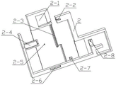
Fig. 7 is a schematic structural diagram of a perspective cross-sectional view of an apparatus housing 2 of an intelligent piece goods marking apparatus of the present invention.
Fig. 8 is a schematic perspective view of a marking mechanism 3 of an intelligent piece goods marking apparatus according to the present invention.
Fig. 9 is a schematic perspective view of a cloth winding and releasing mechanism 4 of an intelligent cloth marking apparatus according to the present invention.
Fig. 10 is a schematic perspective view of a filling mechanism 5 of an intelligent piece goods marking apparatus according to the present invention.
Fig. 11 is a schematic perspective view of a lifting baffle mechanism 6 of an intelligent piece goods marking apparatus according to the present invention.
Fig. 12 is a schematic perspective view of the intelligent identification mechanism 7 of the intelligent piece goods marking apparatus according to the present invention.
In the figure: the chip falling mechanism 1 is rotated; 1-1 of a square shell; t-shaped side grooves 1-1-1; a rotary power structure 1-2; 1-2-1 of a positioning block; a central minor axis 1-2-2; a sun gear 1-2-3; a motor for rotation 1-2-4; 1-2-5 of a gear for rotation; 1-3 of a fan and a motor; 1-4 of a strip-shaped fixing plate; 1-5 of a grid plate; impact and adsorption structures 1-6; 1-6-1 of an impact block; 1-6-2 of a small cam; 1-6-3 parts of a cam motor; 1-6-4 of a supporting spring; 1-6-5 parts of plastic grid plate; 1-6-6 parts of a belt; 1-6-7 of a power shaft; an equipment housing 2; a motor fixing groove 2-1; 2-2 of a semicircular groove; a T-shaped groove 2-3 for lifting; 2-4 of a stepped thread groove; 2-5 of a circular groove; short T-shaped grooves 2-6; the hinge holes I are 2-7; a second hinge hole 2-8; a marking mechanism 3; 3-1 of a half-tooth motor; 3-2 of a half gear; 3-3 of a swing square block; 3-4 of an L-shaped block; 3-5 parts of a bottom spring; 3-6 of an H-shaped connecting piece; pushing the hinged blocks 3-7; 3-8 parts of a marking push plate; marking the material plate 3-9; a cloth winding and releasing mechanism 4; a bottom fixing plate 4-1; a fixing plate 4-2; 4-3 of a motor for winding and releasing; 4-4 parts of cloth shafts; a filling mechanism 5; t-shaped supporting legs 5-1; 5-2 parts of a filler push plate; 5-3 of a filler block; a small swinging piece 5-4; 5-5 of a swing rod; 5-6 of a central shaft; 5-7 of an extrusion pushing piece; 5-8 parts of an adjusting spring; adjusting the threaded part 5-9; 5-9-1 of threads; 5-10 of a poking motor; stirring the cam 5-11; a lifting baffle mechanism 6; a motor 6-1 for lifting; a lifting power gear 6-2; 6-3 of a lifting disc; 6-4 parts of a lifting threaded rod; 6-5 of intermediate gear pieces; an intelligent recognition mechanism 7; a central processing module 7-1; an image pickup apparatus 7-2.
Detailed Description
The first embodiment is as follows:
the embodiment is described below with reference to fig. 1, 2, 3, 4, 5, 6, 7, 8, 9, 10, 11, and 12, and the present invention relates to an intelligent robot, and more specifically to an intelligent cloth marking apparatus, which includes a rotating scrap-dropping mechanism 1, an apparatus housing 2, a marking mechanism 3, a cloth-winding and placing mechanism 4, a filling mechanism 5, a lifting baffle mechanism 6, and an intelligent identification mechanism 7. The rotary scrap falling mechanism 1 is connected with an equipment shell 2, the equipment shell 2 is connected with a marking mechanism 3, a lifting baffle mechanism 6 is connected with the equipment shell 2, the equipment shell 2 is connected with a filling mechanism 5, and the equipment shell 2 is connected with an intelligent recognition mechanism 7.
The second embodiment is as follows:
the present embodiment is described below with reference to fig. 1, 2, 3, 4, 5, 6, 7, 8, 9, 10, 11, and 12, and the present embodiment further describes the present embodiment, where the rotating chip-reducing mechanism 1 includes a square housing 1-1, a rotating power structure 1-2, a fan and motor 1-3, a strip-shaped fixing plate 1-4, a grid plate 1-5, and an impact and adsorption structure 1-6, the square housing 1-1 is connected to the rotating power structure 1-2, the square housing 1-1 is fixedly connected to the strip-shaped fixing plate 1-4, the strip-shaped fixing plate 1-4 is fixedly connected to the fan and motor 1-3, the fan and motor 1-3 are adapted to the square housing 1-1 through a through hole, the square housing 1-1 is fixedly connected to the grid plate 1-5, the grid plate 1-5 is connected with the impact and adsorption structure 1-6, and the impact and adsorption structure 1-6 is connected with the square shell 1-1; a T-shaped side groove 1-1-1 is arranged on the square shell 1-1; the rotary power structure 1-2 comprises a positioning block 1-2-1, a central short shaft 1-2-2, a central gear 1-2-3, a rotary motor 1-2-4 and a rotary gear 1-2-5, the positioning block 1-2-1 is fixedly connected with the square shell 1-1, the positioning block 1-2-1 is movably connected with the central short shaft 1-2-2 through a through hole, the central short shaft 1-2-2 is fixedly connected with the central gear 1-2-3 through a through hole, the central gear 1-2-3 is meshed with the rotating gear 1-2-5, the rotating gear 1-2-5 is fixedly connected with the rotating motor 1-2-4, and the rotating motor 1-2-4 is fixedly connected with the positioning block 1-2-1; the impact and adsorption structure 1-6 comprises an impact block 1-6-1, a small cam 1-6-2, a cam motor 1-6-3, a support spring 1-6-4, a plastic grid plate 1-6-5, a belt 1-6-6 and a power shaft 1-6-7, wherein the impact block 1-6-1 is movably connected with a square shell 1-1 through a T-shaped side groove 1-1, the small cam 1-6-2 is fixedly connected with the cam motor 1-6-3, the cam motor 1-6-3 is fixedly connected with the square shell 1-1 through a groove, the impact block 1-6-1 is fixedly connected with the support spring 1-6-4, the support spring 1-6-4 is fixedly connected with the plastic grid plate 1-6-5, the plastic grid plate 1-6-5 is fixedly connected with the square shell 1-1, the plastic grid plate 1-6-5 is in contact connection with the belt 1-6-6, the belt 1-6-6 is connected with the power shaft 1-6-7, and the power shaft 1-6-7 is connected with the square shell 1-1.
Starting a rotating motor 1-2-4 to drive a rotating gear 1-2-5 to drive a central gear 1-2-3 to rotate, enabling the central gear 1-2-3 to synchronously rotate a central short shaft 1-2-2 so as to drive square shells 1-1 at two sides to rotate, thereby enabling the square shells 1-1 to operate circumferentially, sucking fluff floating on cloth by a fan and the motor 1-3, entering a lower layer space of a grid plate 1-5 through the grid plate 1-5, starting a cam motor 1-6-3 to enable a small cam 1-6-2 to downwards extrude an impact block 1-6-1, enabling the impact block 1-6-1 to downwards move to extrude a supporting spring 1-6-4, and when the small cam 1-6-2 is separated from the impact block 1-6-1, the supporting springs 1-6-4 support the impact blocks 1-6-1 to impact the grid plates 1-5, fluff on the grid plates 1-5 is shaken off and enters the lower-layer space, the power shaft 1-6-7 drives the belt 1-6-6 to rotate and rub the plastic grid plates 1-6-5, and the plastic grid plates 1-6-5 generate static electricity to adsorb the fluff.
The third concrete implementation mode:
the present embodiment is described below with reference to fig. 1, 2, 3, 4, 5, 6, 7, 8, 9, 10, 11, and 12, and the present embodiment further describes the present embodiment, in which the device housing 2 is provided with a motor fixing groove 2-1, a semicircular groove 2-2, a T-shaped groove 2-3 for lifting, a stepped thread groove 2-4, a circular groove 2-5, a short T-shaped groove 2-6, a first hinge hole 2-7, and a second hinge hole 2-8.
The fourth concrete implementation mode:
the embodiment is described below with reference to fig. 1, 2, 3, 4, 5, 6, 7, 8, 9, 10, 11, 12, and the embodiment further describes the first embodiment, where the marking mechanism 3 includes a half-tooth motor 3-1, a half gear 3-2, a swing block 3-3, an L-shaped block 3-4, a bottom spring 3-5, an H-shaped connector 3-6, a push hinge block 3-7, a marking push plate 3-8, and a marking plate 3-9, the bottom spring 3-5 is fixedly connected with the device housing 2, the bottom spring 3-5 is fixedly connected with the L-shaped block 3-4, the L-shaped block 3-4 is fixedly connected with the swing block 3-3, the swing block 3-3 is hinged with the H-shaped connector 3-6, the half-tooth motor 3-1 is fixedly connected with the device housing 2, the half-tooth motor 3-1 is fixedly connected with the half gear 3-2, the half gear 3-2 is meshed with the L-shaped block 3-4, the H-shaped connecting piece 3-6 is hinged with the equipment shell 2 through a second hinge hole 2-8, the H-shaped connecting piece 3-6 is hinged with the pushing hinge block 3-7, the pushing hinge block 3-7 is hinged with the marking push plate 3-8, the marking push plate 3-8 is hinged with the equipment shell 2 through a first hinge hole 2-7, and the marking push plate 3-8 is connected with the marking plate 3-9 through a groove gap.
And starting the half-tooth motor 3-1, driving the half gear 3-2 to downwards move the L-shaped block 3-4 by the half-tooth motor 3-1, so that the swinging square block 3-3 pulls the H-shaped connecting piece 3-6, and the H-shaped connecting piece 3-6 pulls the pushing hinge block 3-7 to drive the marking push plate 3-8 to swing, so that the marking plate 3-9 intermittently swings, and the marking of the cloth by the marking plate 3-9 is realized.
The fifth concrete implementation mode:
the present embodiment is described below with reference to fig. 1, 2, 3, 4, 5, 6, 7, 8, 9, 10, 11, and 12, and the present embodiment further describes an embodiment, in which the cloth winding and releasing mechanism 4 includes a bottom fixing plate 4-1, a fixing plate 4-2, a motor 4-3 for winding and releasing, and a cloth shaft 4-4, the bottom fixing plate 4-1 is fixedly connected to the device housing 2, the device housing 2 is fixedly connected to the fixing plate 4-2, the motor 4-3 for winding and releasing is fixedly connected to the bottom fixing plate 4-1, the motor 4-3 for winding and releasing is fixedly connected to the cloth shaft 4-4, and the cloth shaft 4-4 is connected to the fixing plate 4-2 through a through hole gap.
The sixth specific implementation mode:
the embodiment is described below with reference to fig. 1, 2, 3, 4, 5, 6, 7, 8, 9, 10, 11, and 12, and the embodiment further describes the embodiment, where the packing mechanism 5 includes a T-shaped support foot 5-1, a packing push plate 5-2, a packing block 5-3, a small swing member 5-4, a swing rod 5-5, a central shaft 5-6, an extrusion push member 5-7, an adjusting spring 5-8, an adjusting screw member 5-9, a motor for shifting 5-10, and a shifting cam 5-11, the adjusting screw member 5-9 is in contact connection with the adjusting spring 5-8, the adjusting spring 5-8 is in contact connection with the extrusion push member 5-7, the adjusting spring 5-8, and the adjusting screw member 5-9 are all located in a stepped screw groove 2-4, the extrusion pushing piece 5-7 is in contact connection with the swinging rod 5-5, the swinging rod 5-5 is fixedly connected with the central shaft 5-6, the central shaft 5-6 is in clearance connection with the equipment shell 2 through a circular groove 2-5, the stirring motor 5-10 is fixedly connected with the equipment shell 2, the stirring motor 5-10 is fixedly connected with the stirring cam 5-11, the swinging rod 5-5 is hinged with the small swinging piece 5-4, the small swinging piece 5-4 is hinged with the packing push plate 5-2, the packing push plate 5-2 is fixedly connected with the T-shaped supporting foot 5-1, the T-shaped supporting foot 5-1 is in clearance connection with the equipment shell 2 through a short T-shaped groove 2-6, and the packing push plate 5-2 is fixedly connected with the packing block 5-3; the adjusting screw thread piece 5-9 is provided with a screw thread 5-9-1, and the adjusting screw thread piece 5-9 is in threaded connection with the equipment shell 2 through the screw thread 5-9-1.
When the camera device 7-2 detects that the color of the mark on the cloth is lightened, the camera device is processed by the central processing module 7-1, the motor 6-1 for lifting is started, the motor 6-1 for lifting drives the lifting power gear 6-2, the lifting disc 6-3 is rotated to drive the threaded rod 6-4 for lifting to move upwards, so that the intermediate baffle piece 6-5 is lifted, the motor 5-10 for pulling is started, the motor 5-10 for pulling drives the pulling cam 5-11 to pull the swinging rod 5-5, the swinging rod 5-5 drives the filler push plate 5-2 to move through the small swinging piece 5-4, so that the filler block 5-3 is attached to the mark plate 3-9, the mark plate 3-9 is added with paint, the adjusting spring 5-8 supports and extrudes the push piece 5-7, the pushing piece 5-7 is extruded to reset the rotating swing rod 5-5, the filling block 5-3 is separated from the marking material plate 3-9, the adjusting threaded piece 5-9 is rotated, the adjusting spring 5-8 is extruded, and the supporting force of the adjusting spring 5-8 on the pushing piece 5-7 is started and adjusted.
The seventh embodiment:
the embodiment is described below with reference to fig. 1, 2, 3, 4, 5, 6, 7, 8, 9, 10, 11, and 12, and the embodiment further describes an embodiment, in which the lifting baffle mechanism 6 includes a lifting motor 6-1, a lifting power gear 6-2, a lifting disk 6-3, a lifting threaded rod 6-4, and an intermediate gear 6-5, the lifting motor 6-1 is fixedly connected to the lifting power gear 6-2, the lifting power gear 6-2 is engaged with the lifting disk 6-3, the lifting disk 6-3 is threadedly connected to the lifting threaded rod 6-4, the lifting threaded rod 6-4 is fixedly connected to the intermediate gear 6-5, the lifting motor 6-1 is fixedly connected to the device housing 2 through a motor fixing groove 2-1, the equipment shell 2 is in clearance connection with the lifting disc 6-3 through the semicircular groove 2-2, and the middle baffle piece 6-5 is in clearance connection with the equipment shell 2 through the lifting T-shaped groove 2-3.
The specific implementation mode is eight:
the present embodiment is described below with reference to fig. 1, 2, 3, 4, 5, 6, 7, 8, 9, 10, 11, and 12, and the present embodiment further describes the present embodiment, in which the intelligent recognition mechanism 7 includes a central processing module 7-1 and an image pickup device 7-2, the central processing module 7-1 is fixedly connected to the image pickup device 7-2, and the central processing module 7-1 is fixedly connected to the device housing 2.
The specific implementation method nine:
the present embodiment is described below with reference to fig. 1, 2, 3, 4, 5, 6, 7, 8, 9, 10, 11, and 12, and the second embodiment is further described in the present embodiment, in which the power shafts 1 to 6 to 7 are provided with a matching motor.
The detailed implementation mode is ten:
the present embodiment will be described with reference to fig. 1, 2, 3, 4, 5, 6, 7, 8, 9, 10, 11, and 12, and the present embodiment further describes the first embodiment, in which two winding and laying mechanisms 4 are provided and located on two sides of the device housing 2.
The use method of the device comprises the following steps: starting a rotating motor 1-2-4 to drive a rotating gear 1-2-5 to drive a central gear 1-2-3 to rotate, enabling the central gear 1-2-3 to synchronously rotate a central short shaft 1-2-2 so as to drive square shells 1-1 at two sides to rotate, thereby enabling the square shells 1-1 to operate circumferentially, sucking fluff floating on cloth by a fan and the motor 1-3, entering a lower layer space of a grid plate 1-5 through the grid plate 1-5, starting a cam motor 1-6-3 to enable a small cam 1-6-2 to downwards extrude an impact block 1-6-1, enabling the impact block 1-6-1 to downwards move to extrude a supporting spring 1-6-4, and when the small cam 1-6-2 is separated from the impact block 1-6-1, the supporting springs 1-6-4 support the impact blocks 1-6-1 to impact the grid plates 1-5, fluff on the grid plates 1-5 is shaken off and enters the lower-layer space, the power shaft 1-6-7 drives the belt 1-6-6 to rotate and rub the plastic grid plates 1-6-5, and the plastic grid plates 1-6-5 generate static electricity to adsorb the fluff.
The number of the cloth winding and releasing mechanisms 4 is two, one is responsible for releasing cloth, the other is responsible for winding cloth, and the cloth passes between the marking material plates 3-9 and the middle blocking pieces 6-5.
And starting the half-tooth motor 3-1, driving the half gear 3-2 to downwards move the L-shaped block 3-4 by the half-tooth motor 3-1, so that the swinging square block 3-3 pulls the H-shaped connecting piece 3-6, and the H-shaped connecting piece 3-6 pulls the pushing hinge block 3-7 to drive the marking push plate 3-8 to swing, so that the marking plate 3-9 intermittently swings, and the marking of the cloth by the marking plate 3-9 is realized.
When the camera device 7-2 detects that the color of the mark on the cloth is lightened, the camera device is processed by the central processing module 7-1, the motor 6-1 for lifting is started, the motor 6-1 for lifting drives the lifting power gear 6-2, the lifting disc 6-3 is rotated to drive the threaded rod 6-4 for lifting to move upwards, so that the intermediate baffle piece 6-5 is lifted, the motor 5-10 for pulling is started, the motor 5-10 for pulling drives the pulling cam 5-11 to pull the swinging rod 5-5, the swinging rod 5-5 drives the filler push plate 5-2 to move through the small swinging piece 5-4, so that the filler block 5-3 is attached to the mark plate 3-9, the mark plate 3-9 is added with paint, the adjusting spring 5-8 supports and extrudes the push piece 5-7, the pushing piece 5-7 is extruded to reset the rotating swing rod 5-5, the filling block 5-3 is separated from the marking material plate 3-9, the adjusting threaded piece 5-9 is rotated, the adjusting spring 5-8 is extruded, and the supporting force of the adjusting spring 5-8 on the pushing piece 5-7 is started and adjusted.
This equipment has the function of mark, has the function of reloading, has the rotatory function that falls the bits, and equipment has the function of adjustment coating dynamics.
It is to be understood that the above description is not intended to limit the present invention, and the present invention is not limited to the above examples, and that various changes, modifications, additions and substitutions which are within the spirit and scope of the present invention and which may be made by those skilled in the art are also within the scope of the present invention.
Claims (3)
1. The utility model provides an intelligence cloth marking device, includes that the rotation falls bits mechanism (1), equipment shell (2), marking mechanism (3), twines cloth and puts cloth mechanism (4), filler mechanism (5), lifting baffle mechanism (6), intelligent recognition mechanism (7), its characterized in that: the rotary scrap falling mechanism (1) comprises a square shell (1-1), a rotary power structure (1-2), a fan and a motor (1-3), a strip-shaped fixing plate (1-4), a grid plate (1-5) and an impact and adsorption structure (1-6), wherein the square shell (1-1) is connected with the rotary power structure (1-2), the square shell (1-1) is fixedly connected with the strip-shaped fixing plate (1-4), the strip-shaped fixing plate (1-4) is fixedly connected with the fan and the motor (1-3), the fan and the motor (1-3) are matched with the square shell (1-1) through holes, the square shell (1-1) is fixedly connected with the grid plate (1-5), the grid plate (1-5) is connected with the impact and adsorption structure (1-6), the impact and adsorption structure (1-6) is connected with the square shell (1-1); a T-shaped side groove (1-1-1) is arranged on the square shell (1-1); the rotary power structure (1-2) comprises a positioning block (1-2-1), a central short shaft (1-2-2), a central gear (1-2-3), a rotary motor (1-2-4) and a rotary gear (1-2-5), wherein the positioning block (1-2-1) is fixedly connected with the square shell (1-1), the positioning block (1-2-1) is movably connected with the central short shaft (1-2-2) through a through hole, the central short shaft (1-2-2) is fixedly connected with the central gear (1-2-3) through a through hole, the central gear (1-2-3) is meshed with the rotary gear (1-2-5), the rotary gear (1-2-5) is fixedly connected with the rotary motor (1-2-4), the rotating motor (1-2-4) is fixedly connected with the positioning block (1-2-1); the impact and adsorption structure (1-6) comprises an impact block (1-6-1), a small cam (1-6-2), a cam motor (1-6-3), a supporting spring (1-6-4), a plastic grid plate (1-6-5), a belt (1-6-6), and a power shaft (1-6-7), wherein the impact block (1-6-1) is movably connected with the square shell (1-1) through a T-shaped side groove (1-1-1), the small cam (1-6-2) is fixedly connected with the cam motor (1-6-3), the cam motor (1-6-3) is fixedly connected with the square shell (1-1) through a groove, the impact block (1-6-1) is fixedly connected with the supporting spring (1-6-4), the supporting spring (1-6-4) is fixedly connected with the plastic grid plate (1-6-5), the plastic grid plate (1-6-5) is fixedly connected with the square shell (1-1), the plastic grid plate (1-6-5) is in contact connection with the belt (1-6-6), the belt (1-6-6) is connected with the power shaft (1-6-7), and the power shaft (1-6-7) is connected with the square shell (1-1);
the device shell (2) is provided with a motor fixing groove (2-1), a semicircular groove (2-2), a T-shaped groove (2-3) for lifting, a stepped thread groove (2-4), a circular groove (2-5), a short T-shaped groove (2-6), a first hinge hole (2-7) and a second hinge hole (2-8);
the marking mechanism (3) comprises a half-tooth motor (3-1), a half gear (3-2), a swing square block (3-3), an L-shaped block (3-4), a bottom spring (3-5), an H-shaped connecting piece (3-6), a pushing hinge block (3-7), a marking push plate (3-8) and a marking plate (3-9), wherein the bottom spring (3-5) is fixedly connected with the equipment shell (2), the bottom spring (3-5) is fixedly connected with the L-shaped block (3-4), the L-shaped block (3-4) is fixedly connected with the swing square block (3-3), the swing square block (3-3) is hinged with the H-shaped connecting piece (3-6), the half-tooth motor (3-1) is fixedly connected with the equipment shell (2), the half-tooth motor (3-1) is fixedly connected with the half gear (3-2), the half gear (3-2) is meshed with the L-shaped block (3-4), the H-shaped connecting piece (3-6) is hinged with the equipment shell (2) through a second hinge hole (2-8), the H-shaped connecting piece (3-6) is hinged with the pushing hinge block (3-7), the pushing hinge block (3-7) is hinged with the marking push plate (3-8), the marking push plate (3-8) is hinged with the equipment shell (2) through a first hinge hole (2-7), and the marking push plate (3-8) is in clearance connection with the marking plate (3-9) through a groove;
the cloth winding and releasing mechanism (4) comprises a bottom fixing plate (4-1), a fixing plate (4-2), a motor (4-3) for winding and releasing and a cloth shaft (4-4), wherein the bottom fixing plate (4-1) is fixedly connected with an equipment shell (2), the equipment shell (2) is fixedly connected with the fixing plate (4-2), the motor (4-3) for winding and releasing is fixedly connected with the bottom fixing plate (4-1), the motor (4-3) for winding and releasing is fixedly connected with the cloth shaft (4-4), and the cloth shaft (4-4) is in clearance connection with the fixing plate (4-2) through a through hole;
the packing mechanism (5) comprises a T-shaped supporting leg (5-1), a packing push plate (5-2), a packing block (5-3), a small swinging piece (5-4), a swinging rod (5-5), a central shaft (5-6), an extrusion push piece (5-7), an adjusting spring (5-8), an adjusting threaded piece (5-9), a motor (5-10) for shifting and a shifting cam (5-11), wherein the adjusting threaded piece (5-9) is in contact connection with the adjusting spring (5-8), the adjusting spring (5-8) is in contact connection with the extrusion push piece (5-7), the adjusting spring (5-8) and the adjusting threaded piece (5-9) are all positioned in a stepped thread groove (2-4), and the extrusion push piece (5-7) is in contact connection with the swinging rod (5-5), the swing rod (5-5) is fixedly connected with the central shaft (5-6), the central shaft (5-6) is in clearance connection with the equipment shell (2) through a circular groove (2-5), the poking motor (5-10) is fixedly connected with the equipment shell (2), the poking motor (5-10) is fixedly connected with the poking cam (5-11), the swing rod (5-5) is hinged with the small swing piece (5-4), the small swing piece (5-4) is hinged with the packing push plate (5-2), the packing push plate (5-2) is fixedly connected with the T-shaped supporting foot (5-1), the T-shaped supporting foot (5-1) is in clearance connection with the equipment shell (2) through a short T-shaped groove (2-6), and the packing push plate (5-2) is fixedly connected with the packing block (5-3); the adjusting threaded part (5-9) is provided with threads (5-9-1), and the adjusting threaded part (5-9) is in threaded connection with the equipment shell (2) through the threads (5-9-1);
the lifting baffle mechanism (6) comprises a lifting motor (6-1), a lifting power gear (6-2), a lifting disc (6-3), a lifting threaded rod (6-4) and an intermediate baffle piece (6-5), wherein the lifting motor (6-1) is fixedly connected with the lifting power gear (6-2), the lifting power gear (6-2) is meshed with the lifting disc (6-3), the lifting disc (6-3) is in threaded connection with the lifting threaded rod (6-4), the lifting threaded rod (6-4) is fixedly connected with the intermediate baffle piece (6-5), the lifting motor (6-1) is fixedly connected with the equipment shell (2) through a motor fixing groove (2-1), the equipment shell (2) is in clearance connection with the lifting disc (6-3) through a semicircular groove (2-2), the middle blocking piece (6-5) is in clearance connection with the equipment shell (2) through a T-shaped groove (2-3) for lifting;
the intelligent identification mechanism (7) comprises a central processing module (7-1) and a camera device (7-2), wherein the central processing module (7-1) is fixedly connected with the camera device (7-2), and the central processing module (7-1) is fixedly connected with the device shell (2);
the rotary scrap falling mechanism (1) is connected with an equipment shell (2), the equipment shell (2) is connected with a marking mechanism (3), a lifting baffle mechanism (6) is connected with the equipment shell (2), the equipment shell (2) is connected with a filling mechanism (5), and the equipment shell (2) is connected with an intelligent recognition mechanism (7).
2. The intelligent cloth marking apparatus of claim 1, wherein: the power shaft (1-6-7) is provided with a matched motor.
3. The intelligent cloth marking apparatus of claim 1, wherein: the number of the cloth winding and releasing mechanisms (4) is two, and the two cloth winding and releasing mechanisms are respectively positioned on two sides of the equipment shell (2).
Priority Applications (1)
| Application Number | Priority Date | Filing Date | Title |
|---|---|---|---|
| CN201910548520.9A CN110144718B (en) | 2019-06-24 | 2019-06-24 | Intelligent cloth marking equipment |
Applications Claiming Priority (1)
| Application Number | Priority Date | Filing Date | Title |
|---|---|---|---|
| CN201910548520.9A CN110144718B (en) | 2019-06-24 | 2019-06-24 | Intelligent cloth marking equipment |
Publications (2)
| Publication Number | Publication Date |
|---|---|
| CN110144718A CN110144718A (en) | 2019-08-20 |
| CN110144718B true CN110144718B (en) | 2021-07-27 |
Family
ID=67596289
Family Applications (1)
| Application Number | Title | Priority Date | Filing Date |
|---|---|---|---|
| CN201910548520.9A Active CN110144718B (en) | 2019-06-24 | 2019-06-24 | Intelligent cloth marking equipment |
Country Status (1)
| Country | Link |
|---|---|
| CN (1) | CN110144718B (en) |
Families Citing this family (2)
| Publication number | Priority date | Publication date | Assignee | Title |
|---|---|---|---|---|
| CN111501314B (en) * | 2020-04-24 | 2021-06-08 | 安徽恒益纺织科技有限公司 | A line drawing device for clothing fabric cutting and a line drawing method thereof |
| CN112030360A (en) * | 2020-08-26 | 2020-12-04 | 平湖佐越机械制造股份有限公司 | Device capable of extruding and marking melt-blown cloth simultaneously |
Citations (7)
| Publication number | Priority date | Publication date | Assignee | Title |
|---|---|---|---|---|
| US4020789A (en) * | 1973-12-05 | 1977-05-03 | Steve Gamvrellis | Fabric marker |
| CN201842997U (en) * | 2010-11-03 | 2011-05-25 | 北京经纬纺机新技术有限公司 | Defect marking device of cloth inspecting machine |
| CN203128907U (en) * | 2012-12-18 | 2013-08-14 | 华侨大学 | Automatic control device of cloth inspecting machine |
| CN103586166A (en) * | 2013-09-26 | 2014-02-19 | 中航锂电(洛阳)有限公司 | Coating production line and on-line automatic identification device thereof |
| CN204138980U (en) * | 2014-08-12 | 2015-02-04 | 童杨益 | A kind of automatic cloth inspection labelling apparatus |
| CN206988368U (en) * | 2017-06-15 | 2018-02-09 | 苏州盛恒兴自动化设备有限公司 | A kind of transmission belt cloth-wrapping machine with automatic marking mechanism |
| CN208362760U (en) * | 2018-05-23 | 2019-01-11 | 绍兴柯桥育达纺染有限公司 | A kind of perching dust removal device |
-
2019
- 2019-06-24 CN CN201910548520.9A patent/CN110144718B/en active Active
Patent Citations (7)
| Publication number | Priority date | Publication date | Assignee | Title |
|---|---|---|---|---|
| US4020789A (en) * | 1973-12-05 | 1977-05-03 | Steve Gamvrellis | Fabric marker |
| CN201842997U (en) * | 2010-11-03 | 2011-05-25 | 北京经纬纺机新技术有限公司 | Defect marking device of cloth inspecting machine |
| CN203128907U (en) * | 2012-12-18 | 2013-08-14 | 华侨大学 | Automatic control device of cloth inspecting machine |
| CN103586166A (en) * | 2013-09-26 | 2014-02-19 | 中航锂电(洛阳)有限公司 | Coating production line and on-line automatic identification device thereof |
| CN204138980U (en) * | 2014-08-12 | 2015-02-04 | 童杨益 | A kind of automatic cloth inspection labelling apparatus |
| CN206988368U (en) * | 2017-06-15 | 2018-02-09 | 苏州盛恒兴自动化设备有限公司 | A kind of transmission belt cloth-wrapping machine with automatic marking mechanism |
| CN208362760U (en) * | 2018-05-23 | 2019-01-11 | 绍兴柯桥育达纺染有限公司 | A kind of perching dust removal device |
Also Published As
| Publication number | Publication date |
|---|---|
| CN110144718A (en) | 2019-08-20 |
Similar Documents
| Publication | Publication Date | Title |
|---|---|---|
| CN103358124B (en) | A kind of articulation automatic assembly equipment and method | |
| CN104708620A (en) | Selective compliance assembly robot | |
| CN106041921A (en) | Six-degree-of-freedom hybrid robot | |
| CN103028936A (en) | Double-nut tightening device with automatic counting function | |
| CN201940711U (en) | Leading screw type automatic tapping machine | |
| CN208336112U (en) | A kind of moving contact of plastic-shell circuit breaker automatic riveted-joint apparatus | |
| CN212146428U (en) | Six-axis light cooperative robot | |
| CN108448803A (en) | A kind of robot servo motors suitable for working long hours in a variety of contexts | |
| CN202137630U (en) | Electric four-station rotary wrist | |
| CN110144718A (en) | A kind of intelligence cloth marking arrangement | |
| CN215811371U (en) | Electromagnetic brake detection platform | |
| CN215625576U (en) | Double-sided tape purpose glassine raw paper winding equipment | |
| CN207072119U (en) | A kind of full-automatic adjustable embossing device | |
| CN113920648B (en) | Intelligent assembling equipment and method for IC card intelligent electric meter | |
| CN204031617U (en) | A kind of placement head | |
| CN104786056B (en) | Working method of sewing machine part assembling machine | |
| CN204553456U (en) | The electrodeless metal grid mesh of a kind of ultraprecise pastes net arrangement automatically | |
| CN219889373U (en) | Mounting bracket for mounting low-voltage LED lamp | |
| CN207881906U (en) | A kind of case of transmission water inspection tooling | |
| CN206036158U (en) | Hand is from dual -purpose and can just direction changing mechanical transmission mechanism | |
| CN208805678U (en) | A kind of plate putting machine suitable for exposure machine | |
| CN215435194U (en) | Automatic helping hand takes off material mechanism | |
| CN209533405U (en) | A kind of intelligent robot transmission mechanism of flexibility and reliability | |
| CN102275736A (en) | Novel structure of loading and unloading manipulator | |
| CN207774475U (en) | A kind of disc type unwrapping wire base device of fast changeable feeding |
Legal Events
| Date | Code | Title | Description |
|---|---|---|---|
| PB01 | Publication | ||
| PB01 | Publication | ||
| SE01 | Entry into force of request for substantive examination | ||
| SE01 | Entry into force of request for substantive examination | ||
| TA01 | Transfer of patent application right |
Effective date of registration: 20210713 Address after: 413000 room 208, building 4, Wanli market, high tech Zone, Yiyang City, Hunan Province Applicant after: Yiyang xiaoxingxing Clothing Co.,Ltd. Address before: 518132 4A Xinli intelligent robot Co., Ltd., building 5, hanhaida hi tech Industrial Park, Tianliao village, Gongming town, Bao'an District, Shenzhen City, Guangdong Province Applicant before: Fu Guohai |
|
| TA01 | Transfer of patent application right | ||
| GR01 | Patent grant | ||
| GR01 | Patent grant |