CN109779936B - But floor fan of automatically regulated height - Google Patents
But floor fan of automatically regulated height Download PDFInfo
- Publication number
- CN109779936B CN109779936B CN201910063475.8A CN201910063475A CN109779936B CN 109779936 B CN109779936 B CN 109779936B CN 201910063475 A CN201910063475 A CN 201910063475A CN 109779936 B CN109779936 B CN 109779936B
- Authority
- CN
- China
- Prior art keywords
- floor fan
- control box
- rotating
- side wall
- sensor
- Prior art date
- Legal status (The legal status is an assumption and is not a legal conclusion. Google has not performed a legal analysis and makes no representation as to the accuracy of the status listed.)
- Active
Links
- 230000001105 regulatory effect Effects 0.000 title claims abstract description 5
- 230000005540 biological transmission Effects 0.000 claims description 22
- 230000017525 heat dissipation Effects 0.000 claims description 15
- 238000004804 winding Methods 0.000 claims description 11
- 230000001681 protective effect Effects 0.000 claims description 10
- 230000002093 peripheral effect Effects 0.000 claims description 3
- 230000033228 biological regulation Effects 0.000 abstract description 2
- 238000003466 welding Methods 0.000 description 6
- 238000007493 shaping process Methods 0.000 description 3
- 238000007664 blowing Methods 0.000 description 2
- 238000001514 detection method Methods 0.000 description 2
- 238000010586 diagram Methods 0.000 description 2
- 230000000694 effects Effects 0.000 description 2
- 238000000034 method Methods 0.000 description 2
- 206010019345 Heat stroke Diseases 0.000 description 1
- 208000027418 Wounds and injury Diseases 0.000 description 1
- 230000004308 accommodation Effects 0.000 description 1
- 230000009286 beneficial effect Effects 0.000 description 1
- 239000000428 dust Substances 0.000 description 1
- 238000009413 insulation Methods 0.000 description 1
- 238000005065 mining Methods 0.000 description 1
- 238000012986 modification Methods 0.000 description 1
- 230000004048 modification Effects 0.000 description 1
- 238000000926 separation method Methods 0.000 description 1
Images




Landscapes
- Structures Of Non-Positive Displacement Pumps (AREA)
Abstract
The invention discloses a floor fan capable of automatically adjusting height, which comprises a counterweight base, a control box and a supporting table, wherein four corners of the lower end of the counterweight base are provided with accommodating grooves, electric telescopic rods are arranged in the accommodating grooves, and the lower ends of the electric telescopic rods are provided with connecting plates. Has the advantages that: through setting up storage groove and electric telescopic handle, can realize convenient the accomodating of universal wheel, can make counter weight base and ground contact after floor fan removes the completion, improve the stationarity of floor fan, through setting up electric putter, ultrasonic ranging sensor, microprocessor and signal send-receiver, can realize the automatically regulated of floor fan height, the loaded down with trivial details of traditional artifical manual regulation has been avoided, improve the practicality of floor fan, through setting up temperature sensor and infrared sensor, can be when indoor temperature surpasss the setting value and near floor fan has the people, realize the automatic start of floor fan, make floor fan more intelligent.
Description
Technical Field
The invention relates to the technical field of floor fans, in particular to a floor fan with an automatically adjustable height.
Background
The floor fan has the main characteristics of large air quantity and low noise. In hot summer, the floor fan has the characteristics of good effects of ventilating and ventilating the indoor, preventing heatstroke and reducing temperature, and improving the environment, and safety when the floor fan is stably placed on the ground. The floor fan can be widely applied to places such as warehouses, workshops, restaurants, homes and the like of industrial and mining enterprises.
Chinese patent with patent number CN201720277088.0 discloses a floor fan support and floor fan, including supporting seat and the telescopic link of setting on the supporting seat, the telescopic link is equipped with strutting arrangement, strutting arrangement includes lug, slip cap, backup pad and vaulting pole, it places box and electric wire storage device to be equipped with the remote control in the backup pad.
Above-mentioned patent still has following not enough in the use, at first lack storage device on it, make the floor fan can't realize the convenient of the complete universal wheel after removing the completion and accomodate, and then reduced the stationarity of floor fan during operation, and it mainly realizes the regulation of floor fan height through artifical manual, the manpower consumes greatly, accommodation process is comparatively loaded down with trivial details, the practicality of floor fan has been reduced, still lack temperature detection and infrared detection device on it in addition, can't realize the automatic start of floor fan when floor fan connects external power supply, the functionality of floor fan has been reduced, therefore need a floor fan that can automatically regulated height to solve current problem promptly.
Disclosure of Invention
The present invention is directed to a floor fan with an automatically adjustable height to solve the above problems.
The invention realizes the purpose through the following technical scheme:
a floor fan capable of automatically adjusting height comprises a counterweight base, a control box and a support table, wherein the four corners of the lower end of the counterweight base are provided with accommodating grooves, electric telescopic rods are arranged in the accommodating grooves, the lower ends of the electric telescopic rods are provided with connecting plates, universal wheels are arranged at the lower ends of the connecting plates, an electric push rod is arranged in the middle of the upper end of the counterweight base, the control box is arranged on one side wall of the electric push rod, a switch is arranged on one side wall of the control box, heat dissipation holes are arranged on the other two side walls of the control box, a power wire is arranged below the heat dissipation holes, one end of the power wire is provided with a plug, a wire winding hook is arranged on the other side wall of the electric push rod, the support table is arranged at the top end of the, a fixed groove is formed in the middle of the upper end of the supporting table, a limiting block is fixed on the inner wall of the fixed groove through a clamping groove, a rotating motor is arranged at the inner bottom end of the supporting table, a rotating seat is arranged at the transmission output end of the rotating motor, a fixed block is arranged on one side wall of the rotating seat, a first pressure sensor is arranged on one side wall of the fixed block, a second pressure sensor is arranged on the other side wall of the fixed block, a casing is arranged at the upper end of the rotating seat, a heat dissipation and sound insulation cover is arranged on one side wall of the casing, a driving motor is arranged in the casing, a transmission shaft is arranged at the transmission output end of the driving motor, a rotating block is arranged at one end of the transmission shaft, fan blades are arranged on the peripheral side wall of the, the control box is internally provided with a microprocessor, a timer is arranged above the microprocessor, and a signal receiver is arranged above the timer.
Furthermore, accomodate the groove shaping in on the counter weight base, electric telescopic handle with the connecting plate and accomodate the groove and be the welding, electric telescopic handle's model is YNT-03, the universal wheel with the connecting plate passes through bolted connection.
Furthermore, electric putter with the counter weight base and the brace table are the welding, the control box with electric putter passes through bolted connection, the switch the control box passes through the draw-in groove to be connected, the louvre shaping in on the control box.
Further, the microprocessor, the timer and the signal transceiver are all connected with the control box through bolts, the type of the microprocessor is STM32, the type of the timer is ATS8, and the type of the signal transceiver is DMX.
Furthermore, the wire winding hook with electric putter welds, the quantity of wire winding hook is two, the power cord with the control box is pegged graft, the plug with the power cord cementing, electric putter's model is DT 500.
Further, temperature sensor and ultrasonic ranging sensor all with the brace table passes through the draw-in groove and connects, temperature sensor's model is PT100, ultrasonic ranging sensor's model is MB 1220.
Further, the rotating electrical machines with it passes through the screw connection to prop up supporting bench, the roating seat with the rotating electrical machines passes through the key-type connection, the fixed block with the roating seat welding, the fixed block adopts the arc structure, pressure sensor one and pressure sensor two all with the fixed block passes through the draw-in groove and connects, pressure sensor one and the model of pressure sensor two is JC25CYG 400.
Further, the casing with the roating seat passes through the screwed connection, the heat dissipation sound-proof housing with the casing links to each other through the mode of card pressure, driving motor with the casing passes through bolted connection, the transmission shaft with driving motor passes through the draw-in groove and connects, rotatory piece with the transmission shaft passes through threaded connection, the fan piece with rotatory piece is pegged graft.
Further, the screw rod with rotatory piece passes through threaded connection, the screw rod with the protection casing welding, the protection casing with the transmission shaft is through rotating and being connected.
Furthermore, the infrared sensor is connected with the protective cover through screws, and the model of the infrared sensor is W3Z-D6.
The specific working principle is as follows: when the floor fan is used, the floor fan is firstly switched on with an external power supply through the plug and the power line, then the switch is pressed to enable the microprocessor, the temperature sensor, the infrared sensor and the signal receiver to work, after the microprocessor works, remote control commands received by the signal receiver can be compiled and converted into driving commands to further drive each part to carry out corresponding command actions, when the height of the floor fan needs to be adjusted, the electric push rod and the ultrasonic ranging sensor can work through the microprocessor, the electric push rod can automatically stretch out and draw back after working, further automatic adjustment of the height of the floor fan is realized, after the ultrasonic ranging sensor works, the lifting height of the floor fan can be measured constantly, and when the floor fan is lifted to a designated height, the lifting height of the floor fan can be fed back to the microprocessor, the electric push rod is stopped to work through the microprocessor, when a fan needs to be used, the driving motor, the pressure sensor I, the pressure sensor II and the rotating motor can be made to work through manual instruction sending, the rotating block and the fan blade can be driven to rotate through the transmission shaft after the driving motor works, so that blowing operation is realized, the rotating motor can drive the rotating seat to rotate after the rotating seat works, when the rotating seat rotates to the point that the pressure sensor I or the pressure sensor II is in contact with the limiting block, the pressure sensor I or the pressure sensor II can feed information back to the microprocessor, the rotating motor is made to rotate reversely through the microprocessor, so that the floor fan can swing left and right, and the temperature sensor can detect indoor temperature constantly after working, whether near infrared sensor work back detectable floor fan someone works, works as temperature sensor senses indoor temperature and surpasss the setting value and infrared sensor senses near the floor fan someone, the accessible microprocessor makes driving motor pressure sensor one pressure sensor two and rotating electrical machines work, and then realizes the automatic start of floor fan for floor fan more intelligence when needs remove the floor fan, at first makes electric telescopic handle work, electric telescopic handle work back can with the universal wheel passes through the connecting plate is released accomodate the groove, and then makes counter weight base and ground separation extract the power cord after, can realize the convenient removal of floor fan.
The invention has the beneficial effects that:
1. by arranging the accommodating groove and the electric telescopic rod, the universal wheels can be conveniently accommodated, the counterweight base can be contacted with the ground after the floor fan is moved, and the stability of the floor fan is improved;
2. by arranging the electric push rod, the ultrasonic ranging sensor, the microprocessor and the signal receiver, the height of the floor fan can be automatically adjusted, the complexity of the traditional manual adjustment is avoided, and the practicability of the floor fan is improved;
3. through setting up temperature sensor and infrared sensor, can be when indoor temperature surpasss the setting value and near the floor fan someone, realize the automatic start of floor fan for floor fan more intelligence.
Drawings
Fig. 1 is a schematic structural diagram of a floor fan with an automatically adjustable height according to the present invention;
FIG. 2 is a cross-sectional view of a support base of a floor fan with automatic height adjustment according to the present invention;
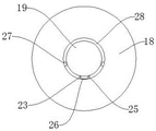
FIG. 3 is a top view of a support base of a floor fan with automatic height adjustment according to the present invention;
FIG. 4 is a cross-sectional view of a counterweight base of a floor fan with automatic height adjustment according to the present invention;
FIG. 5 is a right sectional view of a control box of a floor fan with automatic height adjustment according to the present invention;
fig. 6 is a circuit block diagram of a floor fan with an automatic height adjustment function according to the present invention.
The reference numerals are explained below:
1. a drive shaft; 2. a fan blade; 3. a screw; 4. an infrared sensor; 5. a protective cover; 6. rotating the block; 7. a control box; 8. a switch; 9. a counterweight base; 10. a universal wheel; 11. a plug; 12. a power line; 13. heat dissipation holes; 14. a winding hook; 15. an electric push rod; 16. a temperature sensor; 17. an ultrasonic ranging sensor; 18. a support table; 19. a rotating base; 20. a heat dissipation sound-proof housing; 21. a housing; 22. a drive motor; 23. a first pressure sensor; 24. a rotating electric machine; 25. a second pressure sensor; 26. a fixed block; 27. a limiting block; 28. fixing grooves; 29. a receiving groove; 30. a connecting plate; 31. an electric telescopic rod; 32. a signal receiver; 33. a timer; 34. a microprocessor.
Detailed Description
The invention will be further described with reference to the accompanying drawings in which:
as shown in FIGS. 1-6, a floor fan with automatically adjustable height comprises a counterweight base 9, a control box 7 and a support platform 18, wherein four corners of the lower end of the counterweight base 9 are provided with accommodating grooves 29, an electric telescopic rod 31 is arranged in the accommodating groove 29, the lower end of the electric telescopic rod 31 is provided with a connecting plate 30, the universal wheel 10 can be connected with the electric telescopic rod 31 through the connecting plate 30, the lower end of the connecting plate 30 is provided with the universal wheel 10, the middle part of the upper end of the counterweight base 9 is provided with an electric push rod 15, the electric push rod 15 can automatically extend and retract, so that the floor fan can be automatically lifted, one side wall of the electric push rod 15 is provided with the control box 7, one side wall of the control box 7 is provided with a switch 8, the other two side walls of the control box 7 are provided with heat dissipation holes 13, and, the floor fan is characterized in that a plug 11 is arranged at one end of the power line 12, the floor fan can be connected with an external power supply through the power line 12 and the plug 11, a wire winding hook 14 is arranged on the other side wall of the electric push rod 15, the supporting table 18 is arranged at the top end of the electric push rod 15, an ultrasonic ranging sensor 17 is arranged at the bottom end of the supporting table 18, a temperature sensor 16 is arranged on one side wall of the supporting table 18, a fixing groove 28 is formed in the middle of the upper end of the supporting table 18, a limiting block 27 is fixed on the inner wall of the fixing groove 28 through a clamping groove, a rotating motor 24 is arranged at the bottom end of the supporting table 18, a rotating base 19 is arranged at the transmission output end of the rotating motor 24, a fixing block 26 is arranged on one side wall of the rotating base 19, a first, a casing 21 is arranged at the upper end of the rotary base 19, a heat dissipation sound-proof cover 20 is arranged on one side wall of the casing 21, a driving motor 22 is arranged in the casing 21, the heat dissipation sound-proof cover 20 can effectively reduce noise generated when the driving motor 22 works and can lead heat generated when the driving motor 22 works out of the casing 21 in time, a transmission output end of the driving motor 22 is provided with a transmission shaft 1, one end of the transmission shaft 1 is provided with a rotary block 6, the peripheral side wall of the rotary block 6 is provided with a fan blade 2, one side of the rotary block 6 is provided with a screw rod 3, one end of the screw rod 3 is provided with a protective cover 5, the protective cover 5 can effectively avoid direct contact between a human body and the fan blade 2 in the working process of the floor fan and avoid human body damage, an infrared sensor 4 is arranged on one side wall of the protective cover 5, and a microprocessor, a timer 33 is arranged above the microprocessor 34, and a signal receiver 32 is arranged above the timer 33.
In this embodiment, accomodate groove 29 shaping in on counter weight base 9, electric telescopic handle 31 with connecting plate 30 and accomodate groove 29 and be the welding, electric telescopic handle 31's model is YNT-03, universal wheel 10 with connecting plate 30 passes through bolted connection, through accomodate groove 29 electric telescopic handle 31 can realize convenient the accomodating of universal wheel 10 can make after the floor fan removes the completion counter weight base 9 and ground contact improve the stationarity of floor fan.
In this embodiment, the electric push rod 15, the counterweight base 9 and the supporting table 18 are welded, the control box 7 is connected to the electric push rod 15 through bolts, the switch 8 is connected to the control box 7 through a clamping groove, the heat dissipation holes 13 are formed in the control box 7, and the heat inside the control box 7 can be timely guided out through the heat dissipation holes 13, so that normal operation of each component in the control box 7 is ensured.
In this embodiment, the microprocessor 34, the timer 33, and the signal transceiver 32 are all connected to the control box 7 through bolts, the type of the microprocessor 34 is STM32, the type of the timer 33 is ATS8, the type of the signal transceiver 32 is DMX, and the microprocessor 34 can compile and convert the remote control instruction received by the signal transceiver 32 into a driving instruction, so as to drive each component to perform a corresponding instruction action.
In this embodiment, the wire winding hooks 14 are welded to the electric push rod 15, the number of the wire winding hooks 14 is two, the arrangement of the wire winding hooks 14 enables the power cord 12 and the plug 11 to be wound and hung, so that the power cord 12 and the plug 11 are prevented from being placed anywhere, the power cord 12 is plugged into the control box 7, the plug 11 is glued to the power cord 12, and the model of the electric push rod 15 is DT 500.
In this embodiment, temperature sensor 16 and ultrasonic ranging sensor 17 all with brace table 18 passes through the draw-in groove and connects, temperature sensor 16's model is PT100, ultrasonic ranging sensor 17's model is MB1220, temperature sensor 16 can detect indoor temperature constantly, ultrasonic ranging sensor 17 measurable quantity floor fan's the height of going up and down to can feed back information to microprocessor 34 when floor fan height reaches the setting value.
In this embodiment, the rotating electrical machines 24 with it passes through the screw connection to prop up supporting bench 18, roating seat 19 with the rotating electrical machines 24 passes through the key-type connection, fixed block 26 with 19 welds of roating seat, fixed block 26 adopts the arc structure, pressure sensor 23 and pressure sensor two 25 all with fixed block 26 passes through the draw-in groove and connects, pressure sensor 23 and the model of pressure sensor two 25 is JC25CYG400, pressure sensor 23 and pressure sensor two 25 accessible with stopper 27 contact comes to pass through microprocessor 34 makes the rotating electrical machines 24 reversal, and then realizes the function of swaying about the floor fan.
In this embodiment, the casing 21 with roating seat 19 passes through screwed connection, heat dissipation sound-proof housing 20 with casing 21 links to each other through the mode of card pressure, driving motor 22 with casing 21 passes through bolted connection, casing 21 can for driving motor 22 provides reliable protection, transmission shaft 1 with driving motor 22 passes through the draw-in groove and connects, rotatory piece 6 with transmission shaft 1 passes through threaded connection, fan blade 2 with rotatory piece 6 is pegged graft.
In this embodiment, the screw rod 3 with rotatory piece 6 passes through threaded connection, the screw rod 3 with protection casing 5 welding, protection casing 5 still can play the effect that blocks the dust when playing the guard action, protection casing 5 with transmission shaft 1 is connected through rotating, makes through the connected mode protection casing 5 dismantles more conveniently, is convenient for the clearance of protection casing 5 is maintained.
In this embodiment, the infrared sensor 4 is connected to the protective cover 5 through screws, the infrared sensor 4 is of the type W3Z-D6, and the infrared sensor 4 can detect whether a person is near the floor fan and feed back information to the microprocessor 34.
The specific working principle is as follows: when the lifting height adjusting device is used, the floor fan is firstly switched on through the plug 11 and the power line 12 and an external power supply, then the switch 8 is pressed to enable the microprocessor 34, the temperature sensor 16, the infrared sensor 4 and the signal receiver 32 to work, after the microprocessor 34 works, remote control instructions received by the signal receiver 32 can be compiled and converted into driving instructions through the microprocessor 34, then each component is driven to carry out corresponding instruction actions, when the height of the floor fan needs to be adjusted, the electric push rod 15 and the ultrasonic ranging sensor 17 can work through the microprocessor 34, the electric push rod 15 can automatically stretch out and draw back after working, further automatic adjustment of the height of the floor fan is realized, after the ultrasonic ranging sensor 17 works, the lifting height of the floor fan can be measured at any time, when the floor fan is lifted to a designated height, the lifting height adjusting device can feed back information to the microprocessor 34, the electric push rod 15 is stopped by the microprocessor 34, when the floor fan needs to be used, the driving motor 22, the first pressure sensor 23, the second pressure sensor 25 and the rotary motor 24 can be operated by sending instructions manually, the driving motor 22 can drive the rotary block 6 and the fan blade 2 to rotate through the transmission shaft 1 after operating, so that the blowing operation is realized, the rotary motor 24 can drive the rotary seat 19 to rotate after operating, when the rotary seat 19 rotates until the first pressure sensor 23 or the second pressure sensor 25 contacts with the limiting block 27, the first pressure sensor 23 or the second pressure sensor 25 can feed information back to the microprocessor 34, and the microprocessor 34 enables the rotary motor 24 to rotate reversely, so that the floor fan can swing left and right, the temperature sensor 16 can detect the indoor temperature at any time after working, the infrared sensor 4 can detect whether a person is near the floor fan after working, when the temperature sensor 16 senses that the indoor temperature exceeds the set value and the infrared sensor 4 senses that there is a person near the floor fan, the drive motor 22, the first pressure sensor 23, the second pressure sensor 25 and the rotary motor 24 may be operated by the microprocessor 34, thereby realizing the automatic starting of the floor fan, leading the floor fan to be more intelligent, when the floor fan needs to be moved, firstly leading the electric telescopic rod 31 to work, after the electric telescopic rod 31 works, the universal wheel 10 can be pushed out of the accommodating groove 29 through the connecting plate 30, therefore, the counterweight base 9 is separated from the ground, and then the power cord 12 is pulled out, so that the floor fan can be conveniently moved.
The foregoing illustrates and describes the principles, general features, and advantages of the present invention. It will be understood by those skilled in the art that the present invention is not limited to the embodiments described above, which are described in the specification and illustrated only to illustrate the principle of the present invention, but that various changes and modifications may be made therein without departing from the spirit and scope of the present invention, which fall within the scope of the invention as claimed.
Claims (1)
1. The utility model provides a but floor fan of automatically regulated height which characterized in that: comprises a counterweight base (9), a control box (7) and a supporting table (18), wherein a containing groove (29) is arranged at the four corners of the lower end of the counterweight base (9), an electric telescopic rod (31) is arranged in the containing groove (29), a connecting plate (30) is arranged at the lower end of the electric telescopic rod (31), universal wheels (10) are arranged at the lower end of the connecting plate (30), an electric push rod (15) is arranged in the middle of the upper end of the counterweight base (9), the control box (7) is arranged on one side wall of the electric push rod (15), a switch (8) is arranged on one side wall of the control box (7), radiating holes (13) are arranged on the other two side walls of the control box (7), a power cord (12) is arranged below the radiating holes (13), a plug (11) is arranged at one end of the power cord (12), and a winding hook (14, the top end of the electric push rod (15) is provided with the supporting table (18), the bottom end of the supporting table (18) is provided with an ultrasonic ranging sensor (17), a side wall of the supporting table (18) is provided with a temperature sensor (16), a fixing groove (28) is formed in the middle of the upper end of the supporting table (18), a limiting block (27) is fixed on the inner wall of the fixing groove (28) through a clamping groove, a rotating motor (24) is arranged at the inner bottom end of the supporting table (18), a rotating seat (19) is arranged at the transmission output end of the rotating motor (24), a fixing block (26) is arranged on one side wall of the rotating seat (19), a first pressure sensor (23) is arranged on one side wall of the fixing block (26), a second pressure sensor (25) is arranged on the other side wall of the fixing block (26, a heat dissipation sound-proof cover (20) is arranged on one side wall of the machine shell (21), a driving motor (22) is arranged in the machine shell (21), a transmission output end of the driving motor (22) is provided with a transmission shaft (1), one end of the transmission shaft (1) is provided with a rotating block (6), the peripheral side wall of the rotating block (6) is provided with a fan blade (2), one side of the rotating block (6) is provided with a screw rod (3), one end of the screw rod (3) is provided with a protective cover (5), one side wall of the protective cover (5) is provided with an infrared sensor (4), a microprocessor (34) is arranged in the control box (7), a timer (33) is arranged above the microprocessor (34), and a signal receiver (32) is arranged above the timer (33); when the temperature sensor (16) senses that the indoor temperature exceeds a set value and the infrared sensor (4) senses that a person is nearby the floor fan, the microprocessor (34) enables the driving motor (22), the pressure sensor I (23), the pressure sensor II (25) and the rotating motor (24) to work, and therefore the floor fan is automatically started;
the accommodating groove (29) is formed in the counterweight base (9), the electric telescopic rod (31) is welded with the connecting plate (30) and the accommodating groove (29), and the universal wheel (10) is connected with the connecting plate (30) through a bolt; the electric push rod (15), the counterweight base (9) and the support table (18) are welded, the control box (7) is connected with the electric push rod (15) through bolts, the switch (8) is connected with the control box (7) through a clamping groove, and the heat dissipation holes (13) are formed in the control box (7); the microprocessor (34), the timer (33) and the signal receiver (32) are all connected with the control box (7) through bolts; the winding hooks (14) are welded with the electric push rod (15), the number of the winding hooks (14) is two, the power line (12) is spliced with the control box (7), and the plug (11) is spliced with the power line (12); the temperature sensor (16) and the ultrasonic ranging sensor (17) are connected with the supporting table (18) through clamping grooves; the rotating motor (24) is connected with the supporting table (18) through screws, the rotating base (19) is connected with the rotating motor (24) through a key, the fixing block (26) is welded with the rotating base (19), the fixing block (26) is of an arc-shaped structure, and the pressure sensor I (23) and the pressure sensor II (25) are both connected with the fixing block (26) through clamping grooves; the machine shell (21) is connected with the rotating base (19) through screws, the heat dissipation sound-proof cover (20) is connected with the machine shell (21) in a clamping and pressing mode, the driving motor (22) is connected with the machine shell (21) through bolts, the transmission shaft (1) is connected with the driving motor (22) through a clamping groove, the rotating block (6) is connected with the transmission shaft (1) through threads, and the fan blades (2) are inserted into the rotating block (6); the screw rod (3) is connected with the rotating block (6) through threads, and the screw rod (3) is welded with the protective cover (5); the infrared sensor (4) is connected with the protective cover (5) through screws.
Priority Applications (1)
| Application Number | Priority Date | Filing Date | Title |
|---|---|---|---|
| CN201910063475.8A CN109779936B (en) | 2019-01-23 | 2019-01-23 | But floor fan of automatically regulated height |
Applications Claiming Priority (1)
| Application Number | Priority Date | Filing Date | Title |
|---|---|---|---|
| CN201910063475.8A CN109779936B (en) | 2019-01-23 | 2019-01-23 | But floor fan of automatically regulated height |
Publications (2)
| Publication Number | Publication Date |
|---|---|
| CN109779936A CN109779936A (en) | 2019-05-21 |
| CN109779936B true CN109779936B (en) | 2020-12-04 |
Family
ID=66501142
Family Applications (1)
| Application Number | Title | Priority Date | Filing Date |
|---|---|---|---|
| CN201910063475.8A Active CN109779936B (en) | 2019-01-23 | 2019-01-23 | But floor fan of automatically regulated height |
Country Status (1)
| Country | Link |
|---|---|
| CN (1) | CN109779936B (en) |
Cited By (1)
| Publication number | Priority date | Publication date | Assignee | Title |
|---|---|---|---|---|
| US12537469B2 (en) | 2021-03-12 | 2026-01-27 | Milwaukee Electric Tool Corporation | Portable pedestal fan |
Families Citing this family (2)
| Publication number | Priority date | Publication date | Assignee | Title |
|---|---|---|---|---|
| CN113144303A (en) * | 2021-03-29 | 2021-07-23 | 吉林大学第一医院 | Thyroid puncture drainage device |
| CN114645864A (en) * | 2022-04-01 | 2022-06-21 | 核工业西南物理研究院 | Fan with fan body |
Citations (8)
| Publication number | Priority date | Publication date | Assignee | Title |
|---|---|---|---|---|
| CN2632353Y (en) * | 2003-06-06 | 2004-08-11 | 勋风电器制品(东莞)有限公司 | Oscillating device of multi-directional oscillating electric fan |
| CN104047876A (en) * | 2014-07-07 | 2014-09-17 | 佛山市富士宝电器科技股份有限公司 | Floor fan |
| CN105909543A (en) * | 2016-05-04 | 2016-08-31 | 广东美的环境电器制造有限公司 | Shaking mechanism of household appliances and household appliances |
| CN106351863A (en) * | 2016-10-14 | 2017-01-25 | 郑州朗鑫智能电子科技有限公司 | Intelligent electric fan |
| CN107420331A (en) * | 2017-07-26 | 2017-12-01 | 珠海格力电器股份有限公司 | Oscillating fan |
| CN107588028A (en) * | 2017-09-18 | 2018-01-16 | 于盟盟 | A kind of stand fan |
| CN207568892U (en) * | 2017-09-07 | 2018-07-03 | 中山市世耀智能科技有限公司 | An intelligent energy-saving floor fan |
| CN207961025U (en) * | 2018-03-20 | 2018-10-12 | 宜宾学院 | A kind of wireless regulation and control fan |
Family Cites Families (3)
| Publication number | Priority date | Publication date | Assignee | Title |
|---|---|---|---|---|
| CN203394822U (en) * | 2013-08-21 | 2014-01-15 | 余静宇 | Safety floor fan |
| CN107725445A (en) * | 2017-11-10 | 2018-02-23 | 钦州学院 | A kind of electric fan for automatically adjusting wind-force and inverting wind direction |
| CN108691792A (en) * | 2018-08-09 | 2018-10-23 | 马鞍山松鹤信息科技有限公司 | It is a kind of according to indoor temperature can automatic temperature-control electric fan |
-
2019
- 2019-01-23 CN CN201910063475.8A patent/CN109779936B/en active Active
Patent Citations (8)
| Publication number | Priority date | Publication date | Assignee | Title |
|---|---|---|---|---|
| CN2632353Y (en) * | 2003-06-06 | 2004-08-11 | 勋风电器制品(东莞)有限公司 | Oscillating device of multi-directional oscillating electric fan |
| CN104047876A (en) * | 2014-07-07 | 2014-09-17 | 佛山市富士宝电器科技股份有限公司 | Floor fan |
| CN105909543A (en) * | 2016-05-04 | 2016-08-31 | 广东美的环境电器制造有限公司 | Shaking mechanism of household appliances and household appliances |
| CN106351863A (en) * | 2016-10-14 | 2017-01-25 | 郑州朗鑫智能电子科技有限公司 | Intelligent electric fan |
| CN107420331A (en) * | 2017-07-26 | 2017-12-01 | 珠海格力电器股份有限公司 | Oscillating fan |
| CN207568892U (en) * | 2017-09-07 | 2018-07-03 | 中山市世耀智能科技有限公司 | An intelligent energy-saving floor fan |
| CN107588028A (en) * | 2017-09-18 | 2018-01-16 | 于盟盟 | A kind of stand fan |
| CN207961025U (en) * | 2018-03-20 | 2018-10-12 | 宜宾学院 | A kind of wireless regulation and control fan |
Cited By (1)
| Publication number | Priority date | Publication date | Assignee | Title |
|---|---|---|---|---|
| US12537469B2 (en) | 2021-03-12 | 2026-01-27 | Milwaukee Electric Tool Corporation | Portable pedestal fan |
Also Published As
| Publication number | Publication date |
|---|---|
| CN109779936A (en) | 2019-05-21 |
Similar Documents
| Publication | Publication Date | Title |
|---|---|---|
| CN209184527U (en) | A kind of photovoltaic generating system integrating device easy to remove | |
| CN109779936A (en) | It is a kind of can automatic controlled height stand fan | |
| CN216328950U (en) | AC/DC dual-purpose firewood chopping machine | |
| CN216099479U (en) | Direct current firewood chopping machine | |
| CN206795504U (en) | A kind of frequency conversion angle electric mill power driven tools | |
| CN212304812U (en) | A charger with battery overheating protection function | |
| CN215789692U (en) | Novel mechanical electrical equipment intelligent maintenance device | |
| CN214114844U (en) | A lifting platform for equipment maintenance | |
| CN204793793U (en) | Crank anticreep operation tool | |
| CN209790837U (en) | Automatic induction power-off device of mahjong machine | |
| CN212350241U (en) | Bending-resistant computer connecting and trimming device | |
| CN223864702U (en) | Integrated equipment for discharging outside new energy vehicle | |
| CN215034073U (en) | Brake device for lithium electric circular saw | |
| CN220270608U (en) | Noise detection mechanism | |
| CN219840753U (en) | Cabin intelligent vibration monitoring and early warning device | |
| CN208103590U (en) | A kind of packing storing unit | |
| CN213846570U (en) | A brushless DC motor controller for electric tools | |
| CN113664939A (en) | AC/DC dual-purpose firewood chopping machine | |
| CN221885659U (en) | One-machine one-gate one-protection type mobile power box | |
| CN218331815U (en) | An on-line overvoltage monitoring device for safe communication equipment | |
| CN221489283U (en) | Hair drier | |
| CN221301586U (en) | Air conditioner fan convenient to move | |
| CN221103725U (en) | Overheat preventing device for electrical equipment | |
| CN216435597U (en) | Dry-type transformer does not have fan blade cooling blower device | |
| CN215772958U (en) | Equipment control device convenient to get piece |
Legal Events
| Date | Code | Title | Description |
|---|---|---|---|
| PB01 | Publication | ||
| PB01 | Publication | ||
| SE01 | Entry into force of request for substantive examination | ||
| SE01 | Entry into force of request for substantive examination | ||
| TA01 | Transfer of patent application right |
Effective date of registration: 20201111 Address after: Room 1410, unit 1, giant Ding international commercial building, Taizhou, Zhejiang Province, 318001 Applicant after: Taizhou Xinkai Technology Service Co., Ltd Address before: 271406 Chaoyang Road, Zhaozhuang village, Heshan Township, Tai'an, Shandong Province, No. 4, Chaoyang Road, 22 Applicant before: Wang Jialin |
|
| TA01 | Transfer of patent application right | ||
| GR01 | Patent grant | ||
| GR01 | Patent grant |