CN109700621B - Traditional chinese medical science paediatrics massage device - Google Patents
Traditional chinese medical science paediatrics massage device Download PDFInfo
- Publication number
- CN109700621B CN109700621B CN201910164146.2A CN201910164146A CN109700621B CN 109700621 B CN109700621 B CN 109700621B CN 201910164146 A CN201910164146 A CN 201910164146A CN 109700621 B CN109700621 B CN 109700621B
- Authority
- CN
- China
- Prior art keywords
- plate
- fixed
- massage
- sliding
- roller
- Prior art date
- Legal status (The legal status is an assumption and is not a legal conclusion. Google has not performed a legal analysis and makes no representation as to the accuracy of the status listed.)
- Active
Links
Images


Abstract
The invention relates to a traditional Chinese medicine pediatric massage device, which effectively solves the problems of physical strength consumption, poor massage effect, no cooperation of children and low treatment efficiency in the existing massage process; the technical scheme includes that the bed comprises a bed body and a bed board, wherein a tightening device and a massage device are arranged on the bed board, the tightening device comprises a tightening ring which is in rotating fit with the front portion of the bed board, teeth are arranged on the inner wall of the tightening ring and are meshed with gears, two leg hooping plates are in sliding fit with the rear portion of the bed board, racks are fixed at the lower ends of the two leg hooping plates, a second gear which is meshed with the two racks is arranged between the two racks, and the second gear is connected with the gears through a rotating shaft; the massage device comprises a steel frame fixed at the upper end of the bed plate, the steel frame is matched with the reciprocating device in a sliding manner along the front-back direction, the lower end of the reciprocating device is connected with a roller, the inside of the roller is matched with the massage roller in a rotating manner, and the outer side of the massage roller is fixed with a rubber massage column; the invention has the advantages of ingenious structure, strong practicability and good massage and massage treatment effects.
Description
Technical Field
The invention relates to the technical field of traditional Chinese medicine massage devices, in particular to a traditional Chinese medicine pediatric massage device.
Background
The traditional Chinese medicine massage can relax muscles and tendons, promote blood circulation, dispel wind, relieve pain, and dredge channels and collaterals and acupuncture points of a human body to achieve the effects of treating diseases and relaxing; regarding the names of tuina and massage, the northern habit is called massage, while the southern one is often called tuina, which are the same in meaning but different in name; massage is a consistent name since ancient times, and comes from the most common methods, the pressing method and the massage method; tuina is a term commonly used in ancient times for infant massage, and is named because infants have weak and thin bodies and can only use mild manipulations such as tuina and Na, and is different from adult massage; that is, the massage manipulation is light and the massage force is strong.
Infant tuina, also known as "infant massage", is a traditional Chinese medicine external treatment (physical therapy) for preventing and treating diseases by applying manipulations to specific acupoints or parts on the body surface of a child according to the physiological and pathological characteristics of the child under the guidance of the basic theories of traditional Chinese medicine science and traditional Chinese medicine tuina, and has the health-care functions of promoting intelligence, stimulating appetite, promoting growth, enhancing immunologic function, etc.
Tuina is directly performed by manipulation, and through reinforcing and reducing acupoints, it can regulate gastrointestinal peristalsis, improve gastrointestinal blood circulation, promote lymphatic return, accelerate secretion of digestive juice, various enzymes and antibodies, promote inflammation elimination, and facilitate tissue repair. The actions of infant tuina can be summarized as balancing yin and yang, harmonizing viscera, dredging meridians, promoting qi and blood circulation, strengthening body resistance and eliminating pathogenic factors.
At present, the fingers, the palms or a certain part of the fingers and the palms are used for massaging the certain part of the patient in the traditional Chinese medicine, so that the blood circulation is accelerated, the microcirculation is promoted to be smooth, the channels and the collaterals are dredged, and a certain medical effect is achieved.
Because the massage time is longer, consume a large amount of physical power in the doctor's massage process, all be a very big burden to doctor's mind and body, under the condition that the patient is more, doctor's work is wasted time and energy, and the patient is probably because doctor's physical power is not enough moreover, causes the not good of massage effect.
In addition, in the course of child massage, the child is not fit with the massage apparatus, which may cause poor massage effect and easily affect the treatment efficiency.
Due to the technical defects in the prior art, the technical problems to be solved by the technical personnel in the field are urgent; therefore, a traditional Chinese medicine pediatric massage device is very important.
Disclosure of Invention
Aiming at the situation, in order to overcome the defects of the prior art, the invention provides a traditional Chinese medicine pediatric massage device, which effectively solves the problems that a large amount of physical strength is consumed in the existing massage process, the physical and mental burden of doctors is great, the time and labor are wasted by the doctors when the number of patients is large, the massage effect of the patients is not good probably due to insufficient physical strength of the doctors, and the treatment efficiency is low due to the unmatched situation of the children in the process of massage for the children.
The bed comprises a bed body and a bed plate and is characterized in that a hooping device and a massaging device are arranged at the upper end of the bed plate, the hooping device comprises a semi-annular hooping ring which is arranged at the upper end of the front part of the bed plate in a rotating fit mode, the hooping ring is initially arranged at the lower end of the bed plate and can rotate to the upper end of the bed plate, teeth are uniformly distributed on the circumference of the inner wall of the hooping ring, the teeth are meshed with gears, and the gears are in rotating fit with the bed plate and are arranged at the lower end of the;
the upper end of the rear part of the bed plate is provided with two inverted L-shaped hoop leg plates in a sliding fit manner along the left-right direction, the two hoop leg plates can slide towards the middle direction and can be closed into an n shape, racks arranged along the left-right direction at the lower end of the bed plate are fixed at the lower ends of the two hoop leg plates, a second gear meshed with the two racks is arranged between the two racks, the second gear is fixedly connected with the gears through a rotating shaft fixed coaxially, and a rotating handle arranged outside the bed plate is fixed at the rear end of the rotating shaft;
the massage device comprises a steel frame fixed at the upper end of the bed board, the steel frame is provided with a reciprocating motion device in a sliding fit manner along the front-back direction, the lower end of the reciprocating motion device is connected with a semi-cylindrical hollow roller through a telescopic rod, the roller is rotatably matched with a massage roller with the lower end arranged outside the roller, rubber massage columns are uniformly arranged and fixed on the outer side of the massage roller, and the massage roller is controlled and driven by a driving motor fixed on the outer side of the roller.
Preferably, a semi-annular auxiliary tightening plate is fixed at the rear end of the tightening ring, a plurality of tightening columns are arranged on the auxiliary tightening plate in a sliding fit manner, the tightening columns are arranged at the top end of the outer side part of the auxiliary tightening plate and fixedly connected with the auxiliary tightening plate through springs, sponge blocks are fixed at the parts of the tightening columns, which are arranged at the inner side of the auxiliary tightening plate, sliding blocks are fixed at the outer side of the tightening ring, and sliding rails in sliding fit with the sliding blocks are arranged on the bed plate;
the gear is coaxially fixed with a belt pulley, and the belt pulley is provided with a second belt pulley which is coaxially and fixedly connected with a second gear in a transmission matching manner through a belt.
Preferably, the position that the hooping ring rear end is placed on the bed board upper end is fixed and is provided with the elasticity bridle, the one end and the bed board of elasticity bridle are fixed to be set up, the other end of elasticity bridle passes through movable buckle and the bed board activity is fixed to be set up.
Preferably, the front end and the rear end of the leg hoop plate are both fixed with second sliding blocks, and the leg hoop plate slideway arranged on the bed plate along the left-right direction is provided with corresponding second sliding chutes; the inner side of the leg hooping plate is fixed with a spongy cushion.
Preferably, the reciprocating device comprises a sliding plate which is arranged in a sliding fit with a steel frame, the sliding plate is arranged along the left and right direction, sliding rings which are arranged in a sliding fit with the steel frame are fixed on the left and right sides of the sliding plate, a telescopic rod is fixed at the lower end of the sliding plate, fixed plates are fixed at the front end and the rear end of the steel frame, third belt pulleys are arranged at the lower ends of the two fixed plates in a rotating fit manner, the two third belt pulleys are in transmission fit through a driving belt, a second driving motor arranged at the upper end of the fixed plate is arranged on any one of the third belt pulleys, and a bayonet lock is fixed on the;
the upper ends of the left side and the right side of the sliding plate are respectively provided with a driving block in a rotating fit mode, the inner sides of the two driving blocks are respectively fixed with a clamping hook capable of being clamped by a clamping pin, the outer sides of the upper ends of the two driving blocks are respectively fixed with a clamping plate, and the upper end of the sliding plate is fixed with two clamping columns respectively corresponding to the two clamping plates, so that the two driving blocks cannot rotate towards the inner sides;
the lower extreme of two the drive block all is fixed with and arranges in the turning block of slide lower extreme, the both ends of steelframe all are fixed with the fore-set, make when the turning block withstands the fore-set, the drive block is towards outside rotation, works as when the drive block is towards outside rotation, the bayonet lock can not block the trip.
Preferably, both ends of the steel frame are fixed with adjusting plates, the two ejection columns are arranged in a threaded fit with the two adjusting plates respectively, and adjusting rotating handles are fixed on the outer sides of the two ejection columns.
Preferably, spring plates are fixed at the upper ends of the left side and the right side of the sliding plate, and the two clamping plates are fixedly connected with the two spring plates through reset springs respectively.
Preferably, the telescopic link includes the first slide with slide fixed connection, the inside of first slide is provided with the second slide along vertical direction sliding fit, the lower extreme of first slide is seted up threaded hole, the second slide evenly is provided with a plurality of second screw holes along vertical direction, threaded hole and second screw hole can be adjusted fixedly via adjusting bolt, the outside of second slide upper end is provided with the anticreep board, the inboard of first slide lower extreme is provided with the second anticreep board.
Preferably, a connecting plate is fixed at the lower end of the second sliding plate, the lower end of the connecting plate is fixedly connected with the roller through an adjusting spring, and a second telescopic rod for connecting the second sliding plate and the roller is arranged on the inner side of the adjusting spring;
the lower extreme normal running fit of connecting plate is provided with the cam, the cam is provided with the third driving motor who fixes in the connecting plate outside, the cylinder of lower extreme can be contradicted when the cam rotates, adjusting spring is stretched this moment.
Preferably, a roller cover plate is arranged on the left side of the roller in a rotating fit mode, an arc-shaped cover plate is fixed on the right side of the roller cover plate, the cover plate can cover the lower end of the roller, the cover plate can be arranged on the outer side of the upper end of the roller when rotating, and a handle is fixed on the outer side of the roller cover plate.
The children massage device is ingenious in structure and high in practicability, firstly, the children are fastened by the tightening device, the problem that poor treatment effect is caused by the fact that the children are not matched in the treatment process, the treatment efficiency of massage is influenced, the fastening mode is firm, and the situation that the children struggle and break away in the treatment process is prevented;
the massage device replaces the traditional condition that a doctor carries out manual massage through hands, so that the labor of the doctor is greatly saved, a large amount of physical strength consumption of the doctor is avoided in the longer massage process, the doctor only needs to operate the massage device to carry out massage on a patient, and the problem that the massage efficiency is influenced due to insufficient physical strength of the doctor does not exist;
the stroke problem of regulation reciprocating motion that this device can be fine through the stroke of regulation reciprocating motion, can realize the reciprocating motion massage to different positions of patient, better realization to patient's massage treatment effect.
Drawings
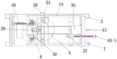
Fig. 1 is a perspective view of the present invention.
FIG. 2 is a schematic side view of the present invention.
Fig. 3 is a perspective view illustrating a usage state of the present invention.
FIG. 4 is a schematic top view of the present invention.
FIG. 5 is a perspective view of the tightening device of the present invention.
Figure 6 is a perspective view of the overall structure of the tightening ring of the present invention.
Fig. 7 is a perspective view of the massage device of the present invention.
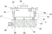
Fig. 8 is a schematic partial cross-sectional view of a massage device of the present invention.
Fig. 9 is a perspective view of a portion of the massage device of the present invention, fig. 1.
FIG. 10 is an enlarged view of the point A in FIG. 4 according to the present invention.
Fig. 11 is a perspective view of a driving block according to the present invention.
FIG. 12 is an enlarged view of FIG. 10 at B.
FIG. 13 is an enlarged view of FIG. 8 at C.
Fig. 14 is a perspective view of a portion of the massage device of the present invention, fig. 2.
Reference numerals: 1. a bed body; 2. a bed board; 3. a tightening device; 4. a massage device; 6. a tightening ring; 7. teeth; 8. a gear; 9. a cuff panel; 10. a rack; 11. a second gear; 12. a rotating shaft; 13. a handle is rotated; 14. a steel frame; 15. a reciprocating device; 16. a telescopic rod; 17. a drum; 18. a massage roller; 19. a rubber massage column; 20. a drive motor; 21. an auxiliary banding plate; 22. tightening the column; 23. a spring; 24. a sponge block; 25. a slider; 26. a slide rail; 27. a belt pulley; 28. a belt; 29. a second pulley; 30. tightening and loosening a binding belt; 31. a second slider; 32. a second chute; 33. a slide plate; 34. a slip ring; 35. a fixing plate; 36. a third belt pulley; 37. a drive belt; 38. a second drive motor; 39. a bayonet lock; 40. a drive block; 41. a hook is clamped; 42. clamping a plate; 43. clamping the column; 44. rotating the block; 45. a top pillar; 46. an adjusting plate; 47. a spring plate; 49. a return spring; 50. a first slide plate; 51. a second slide plate; 52. a threaded hole; 53. a second threaded hole; 54. adjusting the bolt; 55. an anti-drop plate; 56. a second anti-drop plate; 57. a connecting plate; 58. adjusting the spring; 59. a second telescopic rod; 60. a cam; 61. a third drive motor; 62. a roller cover plate; 63. a cover plate; 64. a handle.
Detailed Description
The foregoing and other aspects, features and advantages of the invention will be apparent from the following more particular description of embodiments of the invention, as illustrated in the accompanying drawings in which reference is made to figures 1 to 14. The structural contents mentioned in the following embodiments are all referred to the attached drawings of the specification.
Exemplary embodiments of the present invention will be described below with reference to the accompanying drawings.
In the first embodiment, the invention is a traditional Chinese medicine pediatric massage device, in the course of child massage, because the child is not matched, the poor massage effect is likely to be caused, and the treatment efficiency is easily affected, in order to solve the problem, please refer to fig. 1, which comprises a bed body 1 and a bed plate 2, the lower end of the bed body 1 is provided with wheels, the movement of the device can be realized more conveniently, the upper end of the bed plate 2 is provided with a tightening device 3 and a massage device 4, the tightening device 3 tightens the child, the situation that the massage efficiency is affected due to the unmatched child in the course of massage is avoided, the tightening device 3 comprises the upper end of the front part of the bed plate 2 which is rotatably matched with a semi-annular tightening ring 6, the tightening ring 6 is initially arranged at the lower end of the bed plate 2 and can be rotated to the upper end of the bed plate 2, the inner ring of the tightening ring 6 can be additionally provided with a sponge cushion, teeth 7 are uniformly distributed on the circumference of the inner wall of the hooping ring 6, the teeth 7 are meshed with gears 8, the gears 8 are in rotating fit with the bed plate 2 and are arranged at the lower end of the bed plate 2, please refer to the states of the hooping ring 6 in fig. 1-3, wherein fig. 1 is the state of the hooping ring 6 when the patient is not in use, when the patient lies at the upper end of the bed plate 2, the head is arranged at the front position of the upper end of the bed plate 2, please refer to fig. 1, the head is rested on a headrest, the thoracic cavity is arranged at the upper end of the hooping ring 6, when the gears 8 rotate, the meshed teeth 7 are driven to rotate, so that the rotation of the hooping ring 6 is realized, namely, the process conversion of the hooping ring 6 from the lower end to the upper end of the bed plate 2 is realized, please refer to fig. 3, and the;
in order to tighten the positions of the legs of the patient, please refer to fig. 1 and 2, the upper end of the rear portion of the bed plate 2 is provided with two inverted L-shaped leg hooping plates 9 in a sliding fit manner along the left-right direction, the two leg hooping plates 9 can be closed in an "n" shape by sliding towards the middle direction, that is, the state change of the leg hooping plates 9 in fig. 1-3 is completed, when the patient lies on the upper end of the bed plate 2, the legs are placed between the two leg hooping plates 9, at the moment, the two leg hooping plates 9 are moved towards the opposite positions to fix the positions of the legs of the patient, the positions of the leg hooping plates 9 are set at the positions of the legs, the lower ends of the two leg hooping plates 9 are both fixed with racks 10 arranged at the lower end of the bed plate 2 along the left-right direction, a second gear 11 engaged with the two racks 10 is arranged between the two racks 10, because the real-time second gear 11 is placed at the, when the second gear 11 rotates, the two meshed racks 10 are driven to move towards different directions, so that the hooping of the hooping plate 9 on the leg of the patient or the release of the leg of the patient is realized, the second gear 11 and the gear 8 are fixedly connected through a rotating shaft 12 which is fixed coaxially, a rotating handle 13 which is arranged outside the bed plate 2 is fixed at the rear end of the rotating shaft 12, namely, when the rotating handle 13 rotates, the rotating shaft 12 is driven to rotate, so that the second gear 11 and the gear 8 are driven to rotate, when the second gear 11 rotates, the two meshed racks 10 are driven to move towards different directions, so that the hooping of the hooping plate 9 on the leg of the patient or the release of the leg of the patient is realized, when the gear 8 rotates, the meshed teeth 7 are driven to rotate, so that the hooping ring 6 rotates, namely, the process conversion of the hooping ring 6 from the lower end to the upper end of the bed plate 2 is realized, so that the hooping of the upper trunk and lower limbs of the patient is, the stroke of the patient is adjusted to be consistent, namely, the hooping ring 6 and the hoop leg plate 9 realize synchronous hooping, namely, the realized stroke is consistent, and when the hoop leg plate 9 realizes hooping on both legs of the patient, the hooping ring 6 just realizes hooping on the upper trunk of the patient;
the massage device 4 comprises a steel frame 14 fixed at the upper end of the bed plate 2, please refer to fig. 1, the steel frame 14 is used as a carrier and a guide rail of the massage device 4 to play a role of supporting, the massage device 4 moves along the length direction thereof, and then the massage device 4 performs massage on a patient, the steel frame 14 is provided with a reciprocating device 15 in a sliding fit along the front and back direction, as the massage process is longer, the patient needs to be repeatedly massaged for a long time, then the reciprocating device 15 drives the massage device 4 to reciprocate at the upper end of the patient, and finally the repeated massage effect on the patient is realized, the workload of a doctor is greatly saved, the massage efficiency of the device is improved, please refer to fig. 9, the lower end of the reciprocating device 15 is connected with a semi-cylindrical hollow roller 17 through a telescopic rod 16, the telescopic rod 16 is used for adjusting the height of the massage device 4, namely, adjusting the contact degree of the skin of a patient is realized, and different fat and thin people have different height requirements on the massage device 4, the roller 17 is rotatably matched with a massage roller 18 with the lower end arranged outside the roller 17, the massage roller 18 is used for massaging the patient, please refer to fig. 8 and 9, rubber massage columns 19 are uniformly arranged and fixed outside the massage roller 18, when the device is used, the contact degree of the massage device 4 on the skin of the patient is firstly adjusted through the telescopic rod 16, the massage roller 18 is controlled and driven by a driving motor 20 fixed outside the roller 17, the power supply of the driving motor 20 can adopt an external power supply, and can also adopt a power supply arranged on the device, a control switch of the driving motor 20 is arranged on one side of the bed board 2, or adopt a handheld remote controller, when the driving motor 20 controls the massage roller 18 to rotate, the rubber massage columns 19 fixed on the outer side of the massage roller 18 massage the patient.
In the second embodiment, on the basis of the first embodiment, in order to achieve the tightening effect for patient replacement, please refer to fig. 5 and 6, a semi-annular auxiliary tightening plate 21 is fixed at the rear end of the tightening ring 6, a plurality of tightening posts 22 are arranged on the auxiliary tightening plate 21 in a sliding fit manner, the tightening posts 22 are arranged at the top end of the outer part of the auxiliary tightening plate 21 and fixedly connected with the auxiliary tightening plate 21 through springs 23, a sponge block 24 is fixed at the part of the tightening posts 22 arranged at the inner side of the auxiliary tightening plate 21, the sponge block 24 is a part directly contacted with the patient, in order to protect the patient and prevent the patient from being injured when struggled, here, the patient is protected by the sponge block 24 when tightened, a sliding block 25 is fixed at the outer side of the tightening ring 6, and a sliding rail 26 in sliding fit with the sliding block 25 is arranged on the bed plate 2; referring to fig. 6, when the tightening ring 6 rotates to the upper end of the bed plate 2, the tightening ring 6 completes tightening the upper torso of the patient, and due to different weight and thinness of the patient, the tightening ring 6 may not be suitable for different patients, and referring to fig. 6, when the sponge block 24 contacts the patient, the spring 23 is stretched when the sponge block 24 receives the extrusion force, and then the tightening column 22 completes tightening the patient through the reverse acting force of the spring 23;
because the second gear 11 is disposed in the middle of the two leg hooping plates 9, the teeth of the hooping ring 6 are located at the side, and the two leg hooping plates 9 are required to be arranged in an asymmetrical manner in a coaxial fixed connection, in order to solve the problem, referring to fig. 5, the gear 8 is coaxially fixed with the belt pulley 27, the belt pulley 27 is provided with a second belt pulley 29 which is coaxially and fixedly connected with the second gear 11 through a belt 28 in a transmission fit manner, when the rotating handle 13 rotates, the rotating shaft 12 is driven to rotate, and then the second gear 11 and the second belt pulley 29 which is coaxially and fixedly connected are driven to rotate, and when the second belt pulley 29 rotates, the belt pulley 27 is driven to rotate through the belt 28, and then the gear 8 is driven to rotate, so that the meshed teeth 7 are driven to rotate.
In a third embodiment, on the basis of the second embodiment, in order to achieve the tightening effect for patient replacement, please refer to fig. 1 and fig. 2, a tightening belt 30 is fixedly disposed at a position, at which the rear end of the tightening ring 6 is disposed at the upper end of the bed plate 2, one end of the tightening belt 30 is fixedly disposed on the bed plate 2, and the other end of the tightening belt 30 is movably and fixedly disposed on the bed plate 2 through a movable buckle, where the movable buckle is implemented by using the prior art, such as a clamping rope of a schoolbag and other adjustable buckles that are locked or unlocked.
In the fourth embodiment, on the basis of the first embodiment, in order to make the usage of the leg hoop plate 9 more reasonable and the stability better, please refer to fig. 3 and 5, the front and rear ends of the leg hoop plate 9 are fixed with the second sliding blocks 31, and the slide ways of the leg hoop plate 9, which are arranged along the left and right direction of the bed plate 2, are provided with the corresponding second sliding grooves 32; as the children may struggle in the treatment process, in order to protect the legs from injury, the sponge cushion is fixed on the inner side of the leg hooping plate 9 and can effectively protect the contact positions of the legs of the patient.
Fifth embodiment, on the basis of the first embodiment, in order to make the massage device 4 work better, please refer to fig. 4, fig. 7, fig. 9 and fig. 10, the reciprocating device 15 includes a sliding plate 33 disposed in sliding fit with the steel frame 14, the sliding plate 33 is disposed along the left and right direction, the sliding ring 34 disposed in sliding fit with the steel frame 14 is fixed on each of the left and right sides of the sliding plate 33, the sliding ring 34 slides along the steel frame 14, the lower end of the sliding plate 33 is fixed with the telescopic rod 16, the telescopic rod 16 is used for adjusting the height of the massage device 4, i.e. adjusting the skin contact degree of the patient, and the requirements of different fat and thin people on the height of the massage device 4 are different, the fixing plates 35 are fixed on the front and rear ends of the steel frame 14, the third belt pulleys 36 are disposed on the lower ends of the two fixing plates 35 in rotating fit, the two third belt pulleys 36 are in driving fit via, any one of the third belt pulleys 36 is provided with a second driving motor 38 arranged at the upper end of the fixing plate 35, the power supply of the second driving motor 38 can adopt an external power supply or a power supply installed on the device, a control switch of the second driving motor 38 is arranged at one side of the bed plate 2 or adopts a handheld remote controller for control, and when the second driving motor 38 controls the third belt pulley 36 to rotate, the driving belt 37 is driven to synchronously rotate;
referring to fig. 10, a bayonet 39 is fixed on the outer side of the driving belt 37, and the bayonet 39 rotates synchronously with the driving belt 37 when the driving belt 37 rotates;
referring to fig. 10, the upper ends of the left and right sides of the sliding plate 33 are both rotatably fitted with driving blocks 40, the inner sides of the two driving blocks 40 are both fixed with hooks 41 capable of being clamped by the bayonet pins 39, referring to fig. 4, 10 and 12, when the bayonet pins 39 rotate to the driving blocks 40, the bayonet pins 39 clamp the hooks 41, and then the purpose of driving the driving blocks 40 to move synchronously is achieved, referring to fig. 10, the outer sides of the upper ends of the two driving blocks 40 are both fixed with clamping plates 42, and the upper end of the sliding plate 33 is fixed with two clamping posts 43 respectively corresponding to the two clamping plates 42, so that the two driving blocks 40 cannot rotate towards the inner sides;
the lower ends of the two driving blocks 40 are respectively fixed with a rotating block 44 arranged at the lower end of the sliding plate 33, and the two ends of the steel frame 14 are respectively fixed with an ejection column 45, so that when the rotating blocks 44 eject the ejection columns 45, the driving blocks 40 rotate towards the outside, and when the driving blocks 40 rotate towards the outside, the clamping pins 39 cannot clamp the clamping hooks 41;
in the specific use of the embodiment, first, the second driving motor 38 is turned on, the second driving motor 38 controls the third belt pulley 36 to rotate, so as to drive the driving belt 37 to rotate synchronously, at this time, when the bayonet 39 rotates to the driving block 40 along with the driving belt 37, because the snap plate 42 on the driving block 40 is blocked by the snap column 43, and cannot rotate towards the inside in sequence, please refer to fig. 10, at this time, by applying the principle of lever, the bayonet 39 blocks the snap hook 41, so as to achieve the purpose of driving the driving block 40 to move synchronously, finally, the driving block 40 drives the sliding plate 33 to move along the horizontal direction, when the rotating block 44 is driven to abut against the snap column 45, the driving block 40 rotates towards the outside, when the driving block 40 rotates towards the outside, the bayonet 39 cannot block the snap hook 41, at this time, the bayonet 39 continues to rotate along with the driving belt 37, but the sliding plate 33 cannot move synchronously, referring to fig. 10, when the pin 39 continues to rotate along with the driving belt 37 and moves to another driving block 40, the pin 39 will block another hook 41, so as to drive the driving block 40 to move in the opposite direction, and in the process, the sliding plate 33 reciprocates.
Sixth embodiment, on the basis of the fifth embodiment, because the position of the massage is not fixed, for example, some of the massage needs to perform massage on the abdomen of the patient, some of the massage needs to perform massage on the back of the patient, and the height difference of the patient, etc., the massage on different parts needs different strokes of the reciprocating device 15, please refer to fig. 2 and fig. 3, both ends of the steel frame 14 are fixed with adjusting plates 46, two of the top pillars 45 are respectively arranged in threaded fit with the two adjusting plates 46, and the outer sides of the two top pillars 45 are fixed with adjusting rotating handles 45-1;
when the reciprocating motion device is used specifically, firstly, a patient determines the position needing to be massaged, according to factors such as the height of the patient, at the moment, a doctor determines the region needing to be massaged, when the stroke of the reciprocating motion device 15 needs to be adjusted, only the adjusting rotating handle 45-1 needs to be rotated, then the feeding adjustment of the ejection column 45 in the horizontal direction is realized, the distance between the end parts of the inner sides of the two ejection columns 45 is the reciprocating motion region, namely, when the rotating block 44 abuts against the ejection column 45, the driving block 40 rotates towards the outer side, and the change of the motion direction of the sliding plate 33 is realized.
Seventh, on the basis of the fifth embodiment, in order to ensure that the driving block 40 is more convenient and reasonable to reset after rotating towards the outside, referring to fig. 12, spring plates 47 are fixed at the upper ends of the left and right sides of the sliding plate 33, the two clamping plates 42 are respectively and fixedly connected with the two spring plates 47 through return springs 49, the return springs 49 are stretched after the driving block 40 rotates towards the outside, and when the bayonet pins 39 rotate away, the effective reset of the driving block 40 is further realized through the spring elastic force action of the return springs 49.
In an eighth embodiment, on the basis of the fifth embodiment, in order to achieve better adjustment of the telescopic rod 16, referring to fig. 9 and 13, the telescopic rod 16 includes a first sliding plate 50 fixedly connected to the sliding plate 33, a second sliding plate 51 is slidably fitted inside the first sliding plate 50 along the vertical direction, a threaded hole 52 is formed in the lower end of the first sliding plate 50, a plurality of second threaded holes 53 are uniformly formed in the second sliding plate 51 along the vertical direction, the threaded hole 52 and the second threaded holes 53 can be adjusted and fixed by an adjusting bolt 54, an anti-falling plate 55 is disposed on the outer side of the upper end of the second sliding plate 51, a second anti-falling plate 56 is disposed on the inner side of the lower end of the first sliding plate 50, when the second sliding plate 52 slides along the first sliding plate 51, when the anti-falling plate 55 abuts against the second anti-falling plate 56, the first sliding plate 50 and the second sliding plate 51 cannot continue to move, and it is, when the patient needs to be treated, the doctor adjusts the height of the telescopic rod 16 according to the actual condition, and then the contact degree of the lower end of the massage device 4 and the skin of the patient is adjusted.
In the ninth embodiment, on the basis of the eighth embodiment, in order to achieve better massage effect for the patient, a connecting plate 57 is fixed at the lower end of the second sliding plate 51, please refer to fig. 9 and 14, the lower end of the connecting plate 57 is fixedly connected with the roller 17 through an adjusting spring 58, and a second telescopic rod 59 connecting the second sliding plate 51 and the roller 17 is arranged inside the adjusting spring 58;
the lower extreme normal running fit of connecting plate 57 is provided with cam 60, cam 60 is provided with the third driving motor 61 of fixing in the connecting plate 57 outside, and external power source can be adopted to the power of third driving motor 61, also can be through installing the power on the device, and the control switch setting of third driving motor 61 is in one side of bed board 2, or adopts handheld remote controller control, and when third driving motor 61 control cam 60 rotated, the cylinder 17 of lower extreme can be contradicted when cam 60 rotated, at this moment adjusting spring 58 was stretched, when having realized massage roller 18 then and rotated the massage, vertical direction's reciprocating motion.
When driving motor 20 control massage roller 18 rotated, the fixed rubber massage post 19 in the outside of massage roller 18 carried out massage to the patient, opened third driving motor 61's control switch this moment, and third driving motor 61 drive cam 60 rotated, can contradict the cylinder 17 of lower extreme when cam 60 rotated, this moment adjusting spring 58 was stretched, when having realized massage roller 18 then and rotating massage, the reciprocating motion of vertical direction, emulation doctor's massage gimmick has played better massage's purpose to the patient.
In the tenth embodiment, on the basis of the first embodiment, in order to prevent dust from entering when the device is not used, referring to fig. 1, 9 and 14, a roller cover plate 62 is rotatably fitted on the left side of the roller 17, an arc-shaped cover plate 63 is fixed on the right side of the roller cover plate 62, the cover plate 63 can cover the lower end of the roller 17, the cover plate 63 can be placed on the outer side of the upper end of the roller 17 when rotating, a handle 64 is fixed on the outer side of the roller cover plate 62, and a doctor can adjust the position of the roller cover plate 62 by rotating the roller cover plate 62 through the handle 64.
When the invention is used in detail, firstly, when a patient lies on the upper end of the bed board 2, the head is arranged at the front position of the upper end of the bed board 2, please refer to fig. 1, the head is rested on the headrest, the chest position is arranged at the upper end of the hooping ring 6, at this time, a doctor rotates the rotating handle 13 to drive the rotating shaft 12 to rotate and then drive the second gear 11 and the gear 8 to rotate, when the second gear 11 rotates, the two meshed racks 10 are driven to move towards different directions, thus realizing the hooping of the leg of the patient by the hooping plate 9 or the releasing of the leg of the patient, when the gear 8 rotates, the meshed teeth 7 are driven to rotate and then realize the rotation of the hooping ring 6, namely realizing the conversion from the rotation of the lower end of the bed board 2 to the process of the hooping ring 6, and then realizing the hooping of the upper trunk and lower limbs of the patient, the stroke at the position is adjusted to be consistent, namely, the hooping of the, namely, the realized strokes are consistent, and when the leg hooping plates 9 are used for hooping the two legs of the patient, the hooping rings 6 are used for just hooping the upper trunk of the patient;
when the hooping ring 6 rotates to the upper end of the bed plate 2, the hooping ring 6 hoops the upper torso of the patient, and due to different weight and thinness of the patient, the hooping ring 6 may not be suitable for different patients, at this time, please refer to fig. 6, when the sponge block 24 contacts the patient, the spring 23 is stretched, and then the hooping column 22 hoops the patient by the reverse acting force of the spring 23;
then the patient determines the position to be massaged, according to the height of the patient and other factors, the doctor determines the section to be massaged, when the stroke of the reciprocating motion device 15 needs to be adjusted, the doctor only needs to rotate the adjusting rotating handle 45-1, then the feeding adjustment of the ejection columns 45 in the horizontal direction is realized, the distance between the inner side end parts of the two ejection columns 45 is the reciprocating motion section, namely when the rotating block 44 abuts against the ejection columns 45, the driving block 40 rotates towards the outer side, and the change of the motion direction of the sliding plate 33 is realized;
at this time, the second driving motor 38 is turned on, the second driving motor 38 controls the third belt pulley 36 to rotate, so as to drive the driving belt 37 to rotate synchronously, at this time, when the bayonet pin 39 rotates to the driving block 40 along with the driving belt 37, because the snap plate 42 on the driving block 40 is snapped by the snap column 43, and cannot rotate towards the inside in turn, please refer to fig. 10, applying the principle of lever, the bayonet pin 39 will snap the snap hook 41, so as to drive the driving block 40 to move synchronously, finally the driving block 40 drives the sliding plate 33 to move along the horizontal direction, when the rotating block 44 is driven to abut against the snap column 45, the driving block 40 rotates towards the outside, when the driving block 40 rotates towards the outside, the bayonet pin 39 cannot snap the snap hook 41, at this time, the bayonet pin 39 continues to rotate along with the driving belt 37, but the sliding plate 33 cannot move synchronously, referring to fig. 10, when the bayonet 39 continues to rotate along with the driving belt 37 and moves to another driving block 40, the bayonet 39 will block another hook 41, so as to drive the driving block 40 to move in the opposite direction, and in this process, the sliding plate 33 reciprocates;
when a patient needs to be treated, a doctor adjusts the height of the telescopic rod 16 according to the actual condition, and then the contact degree between the lower end of the massage device 4 and the skin of the patient is adjusted;
when driving motor 20 control massage roller 18 rotated, the fixed rubber massage post 19 in the outside of massage roller 18 carried out massage to the patient, opened third driving motor 61's control switch this moment, and third driving motor 61 drive cam 60 rotated, can contradict the cylinder 17 of lower extreme when cam 60 rotated, this moment adjusting spring 58 was stretched, when having realized massage roller 18 then and rotating massage, the reciprocating motion of vertical direction, emulation doctor's massage gimmick has played better massage's purpose to the patient.
The children massage device is ingenious in structure and high in practicability, firstly, the children are fastened by the tightening device, the problem that poor treatment effect is caused by the fact that the children are not matched in the treatment process, the treatment efficiency of massage is influenced, the fastening mode is firm, and the situation that the children struggle and break away in the treatment process is prevented;
the massage device replaces the traditional condition that a doctor carries out manual massage through hands, so that the labor of the doctor is greatly saved, a large amount of physical strength consumption of the doctor is avoided in the longer massage process, the doctor only needs to operate the massage device to carry out massage on a patient, and the problem that the massage efficiency is influenced due to insufficient physical strength of the doctor does not exist;
the stroke problem of regulation reciprocating motion that this device can be fine through the stroke of regulation reciprocating motion, can realize the reciprocating motion massage to different positions of patient, better realization to patient's massage treatment effect.
Claims (10)
1. A traditional Chinese medicine pediatric massage device comprises a bed body (1) and a bed plate (2), and is characterized in that a tightening device (3) and a massage device (4) are arranged at the upper end of the bed plate (2), the tightening device (3) comprises a semi-annular tightening ring (6) which is arranged at the upper end of the front portion of the bed plate (2) in a rotating fit mode, the tightening ring (6) is arranged at the lower end of the bed plate (2) in an initial state and can rotate to the upper end of the bed plate (2), teeth (7) are uniformly distributed on the circumference of the inner wall of the tightening ring (6), the teeth (7) are meshed with gears (8), and the gears (8) are in rotating fit with the bed plate (2) and are arranged at the lower end of the bed plate (2);
the upper end of the rear part of the bed plate (2) is provided with two inverted L-shaped hoop leg plates (9) in a sliding fit manner along the left-right direction, the two hoop leg plates (9) can slide towards the middle direction and can be closed into an n-shaped state, the lower ends of the two hoop leg plates (9) are respectively fixed with a rack (10) arranged at the lower end of the bed plate (2) along the left-right direction, a second gear (11) meshed with the two racks (10) is arranged between the two racks (10), the second gear (11) is fixedly connected with a gear (8) through a rotating shaft (12) fixed with the same axle center, and the rear end of the rotating shaft (12) is fixedly provided with a rotating handle (13) arranged outside the bed plate (2);
massage device (4) are including fixed steelframe (14) in bed board (2) upper end, steelframe (14) are provided with reciprocating motion device (15) along fore-and-aft direction sliding fit, the lower extreme of reciprocating motion device (15) is connected with hollow cylinder (17) of semi-cylindrical inside through telescopic link (16), cylinder (17) normal running fit is provided with the lower extreme and arranges cylinder (17) outside massage roller (18) in, the outside of massage roller (18) evenly sets up and is fixed with rubber massage post (19), massage roller (18) are via fixing driving motor (20) control drive in the cylinder (17) outside.
2. The traditional Chinese medicine pediatric massage device according to claim 1, wherein a semi-annular auxiliary tightening plate (21) is fixed to the rear end of the tightening ring (6), the auxiliary tightening plate (21) is provided with a plurality of tightening posts (22) in a sliding fit manner, the tightening posts (22) are arranged at the top end of the outer side portion of the auxiliary tightening plate (21) and fixedly connected with the auxiliary tightening plate (21) through springs (23), sponge blocks (24) are fixed to the portions, arranged on the inner side of the auxiliary tightening plate (21), of the tightening posts (22), sliding blocks (25) are fixed to the outer side of the tightening ring (6), and sliding rails (26) in a sliding fit manner with the sliding blocks (25) are arranged on the bed plate (2);
the gear (8) is coaxially fixed with a belt pulley (27), and the belt pulley (27) is provided with a second belt pulley (29) which is coaxially and fixedly connected with the second gear (11) through a belt (28) in a transmission matching manner.
3. The traditional Chinese medicine pediatric massage device according to claim 2, wherein an elastic band (30) is fixedly arranged at the rear end of the hooping ring (6) at the upper end of the bed plate (2), one end of the elastic band (30) is fixedly arranged with the bed plate (2), and the other end of the elastic band (30) is movably and fixedly arranged with the bed plate (2) through a movable buckle.
4. The traditional Chinese medicine pediatric massage device according to claim 1, wherein the front end and the rear end of the leg hoop plate (9) are both fixed with second sliding blocks (31), and a corresponding second sliding chute (32) is formed in a slide way of the leg hoop plate (9) formed in the left-right direction of the bed plate (2); a spongy cushion is fixed on the inner side of the leg hooping plate (9).
5. The pediatric massage apparatus of traditional Chinese medicine according to claim 1, wherein the reciprocating device (15) comprises a sliding plate (33) slidably engaged with the steel frame (14), the sliding plate (33) is arranged along the left and right direction, the left and right sides of the sliding plate (33) are both fixed with sliding rings (34) which are arranged in sliding fit with the steel frame (14), the lower end of the sliding plate (33) is fixed with a telescopic rod (16), the front end and the rear end of the steel frame (14) are both fixed with fixing plates (35), the lower ends of the two fixing plates (35) are both provided with third belt pulleys (36) in a rotating fit mode, the two third belt pulleys (36) are in transmission fit through a driving belt (37), any one third belt pulley (36) is provided with a second driving motor (38) arranged at the upper end of the fixing plate (35), and the outer side of the driving belt (37) is fixed with a clamping pin (39);
the upper ends of the left side and the right side of the sliding plate (33) are respectively provided with a driving block (40) in a rotating fit mode, the inner sides of the two driving blocks (40) are respectively fixed with a clamping hook (41) capable of being clamped by a clamping pin (39), the outer sides of the upper ends of the two driving blocks (40) are respectively fixed with a clamping plate (42), and the upper end of the sliding plate (33) is fixed with two clamping columns (43) which are respectively arranged corresponding to the two clamping plates (42), so that the two driving blocks (40) cannot rotate towards the inner sides;
two the lower extreme of drive block (40) all is fixed with and arranges in turning block (44) of slide (33) lower extreme, the both ends of steelframe (14) all are fixed with fore-set (45), make when turning block (44) withhold fore-set (45), drive block (40) are towards outside rotation, work as when drive block (40) are towards outside rotation, bayonet lock (39) can not block trip (41).
6. The traditional Chinese medicine pediatric massage device according to claim 5, wherein adjusting plates (46) are fixed at both ends of the steel frame (14), the two top pillars (45) are respectively in threaded fit with the two adjusting plates (46), and adjusting rotating handles (45-1) are fixed at the outer sides of the two top pillars (45).
7. The traditional Chinese medicine pediatric massage device according to claim 5, wherein spring plates (47) are fixed at the upper ends of the left side and the right side of the sliding plate (33), and the two clamping plates (42) are respectively and fixedly connected with the two spring plates (47) through return springs (49).
8. The traditional Chinese medicine pediatric massage device according to claim 5, wherein the telescopic rod (16) comprises a first sliding plate (50) fixedly connected with a sliding plate (33), a second sliding plate (51) is arranged inside the first sliding plate (50) in a sliding fit in the vertical direction, a threaded hole (52) is formed in the lower end of the first sliding plate (50), a plurality of second threaded holes (53) are uniformly formed in the second sliding plate (51) in the vertical direction, the threaded holes (52) and the second threaded holes (53) can be adjusted and fixed through adjusting bolts (54), an anti-falling plate (55) is arranged on the outer side of the upper end of the second sliding plate (51), and a second anti-falling plate (56) is arranged on the inner side of the lower end of the first sliding plate (50).
9. The traditional Chinese medicine pediatric massage device according to claim 8, wherein a connecting plate (57) is fixed at the lower end of the second sliding plate (51), the lower end of the connecting plate (57) is fixedly connected with the roller (17) through an adjusting spring (58), and a second telescopic rod (59) connecting the second sliding plate (51) and the roller (17) is arranged at the inner side of the adjusting spring (58);
the lower end of the connecting plate (57) is provided with a cam (60) in a rotating fit mode, the cam (60) is provided with a third driving motor (61) fixed to the outer side of the connecting plate (57), the cam (60) can abut against a roller (17) at the lower end when rotating, and at the moment, the adjusting spring (58) is stretched.
10. The traditional Chinese medicine pediatric massage device according to claim 1, wherein a roller cover plate (62) is rotatably fitted on the left side of the roller (17), an arc-shaped cover plate (63) is fixed on the right side of the roller cover plate (62), the cover plate (63) can cover the lower end of the roller (17), the cover plate (63) can be placed outside the upper end of the roller (17) when the cover plate (63) rotates, and a handle (64) is fixed on the outside of the roller cover plate (62).
Priority Applications (1)
| Application Number | Priority Date | Filing Date | Title |
|---|---|---|---|
| CN201910164146.2A CN109700621B (en) | 2019-03-05 | 2019-03-05 | Traditional chinese medical science paediatrics massage device |
Applications Claiming Priority (1)
| Application Number | Priority Date | Filing Date | Title |
|---|---|---|---|
| CN201910164146.2A CN109700621B (en) | 2019-03-05 | 2019-03-05 | Traditional chinese medical science paediatrics massage device |
Publications (2)
| Publication Number | Publication Date |
|---|---|
| CN109700621A CN109700621A (en) | 2019-05-03 |
| CN109700621B true CN109700621B (en) | 2020-11-06 |
Family
ID=66265591
Family Applications (1)
| Application Number | Title | Priority Date | Filing Date |
|---|---|---|---|
| CN201910164146.2A Active CN109700621B (en) | 2019-03-05 | 2019-03-05 | Traditional chinese medical science paediatrics massage device |
Country Status (1)
| Country | Link |
|---|---|
| CN (1) | CN109700621B (en) |
Families Citing this family (9)
| Publication number | Priority date | Publication date | Assignee | Title |
|---|---|---|---|---|
| CN110141481A (en) * | 2019-06-11 | 2019-08-20 | 皖南医学院 | Medical drive lacking massaging manipulator |
| CN110251382B (en) * | 2019-07-04 | 2021-08-24 | 南通大学附属医院 | Pediatric neurology clinical training massage device and use method thereof |
| CN110302041B (en) * | 2019-07-24 | 2021-07-16 | 兰州大学第一医院 | Auxiliary abdominal distension treatment device for digestive system department |
| CN110269793B (en) * | 2019-07-25 | 2021-05-14 | 河南省中医院(河南中医药大学第二附属医院) | Stomach is assisted digestion auxiliary device for traditional chinese medical science gastroenterology |
| CN110916999A (en) * | 2019-12-20 | 2020-03-27 | 长江航运总医院 | Acupuncture and moxibustion rehabilitation massage device |
| CN112891176A (en) * | 2021-01-12 | 2021-06-04 | 南京甜沭行网络科技有限公司 | Digestion promoting equipment for infants |
| CN112870045A (en) * | 2021-01-20 | 2021-06-01 | 深圳市儿童医院 | Auxiliary massage device for infantile digestion treatment |
| CN112972224B (en) * | 2021-02-03 | 2023-03-31 | 董洪贞 | Traditional Chinese medicine pediatric clinical massage method and auxiliary massage device thereof |
| CN114569446B (en) * | 2022-03-02 | 2023-09-05 | 山东中医药大学附属医院 | Traditional chinese medical science pediatrics massage auxiliary device |
Family Cites Families (11)
| Publication number | Priority date | Publication date | Assignee | Title |
|---|---|---|---|---|
| KR102210490B1 (en) * | 2013-11-21 | 2021-02-01 | 코웨이 주식회사 | An massage machine including massage module |
| CN203777239U (en) * | 2014-03-21 | 2014-08-20 | 李淑霞 | Paediatric traditional Chinese medicine diagnosis and treatment table |
| CN105105961A (en) * | 2015-08-14 | 2015-12-02 | 郭保红 | Massage bed |
| CN105769523B (en) * | 2016-03-31 | 2018-07-03 | 李僖年 | A kind for the treatment of and health active massaging device |
| CN208481661U (en) * | 2018-01-15 | 2019-02-12 | 范绪涛 | A kind of spinal surgery treatment lying bed |
| CN108354805B (en) * | 2018-03-12 | 2019-08-09 | 吉林大学 | A kind of medical back massage nursing bed |
| CN108392357B (en) * | 2018-04-28 | 2020-09-11 | 王天牧 | Massage equipment capable of duplicating massage manipulation |
| CN108836798B (en) * | 2018-07-23 | 2020-07-17 | 河南省中医院(河南中医药大学第二附属医院) | Massage equipment for orthopedics |
| CN108992298A (en) * | 2018-08-06 | 2018-12-14 | 李博 | A kind of novel infantile surgery posture fixer device |
| CN109009833A (en) * | 2018-08-13 | 2018-12-18 | 苏州威新锋医疗科技有限公司 | A kind of medical massage bed |
| CN109223489B (en) * | 2018-10-11 | 2021-07-23 | 青岛大学附属医院 | Massager for relieving leg ache |
-
2019
- 2019-03-05 CN CN201910164146.2A patent/CN109700621B/en active Active
Also Published As
| Publication number | Publication date |
|---|---|
| CN109700621A (en) | 2019-05-03 |
Similar Documents
| Publication | Publication Date | Title |
|---|---|---|
| CN109700621B (en) | Traditional chinese medical science paediatrics massage device | |
| CN108852588B (en) | Auxiliary traction device for orthopedics department | |
| CN109758733B (en) | Pelvic floor flesh exercise device | |
| CN111773034A (en) | Automatic rehabilitation equipment for lower limb rehabilitation | |
| CN107669460A (en) | A kind of patients in neurological department head physiotherapy device and its application method | |
| CN108324531B (en) | Waist massage traction bed | |
| CN206777438U (en) | It is a kind of for orthopedic spinal treatment and rehabilitation it is function bed | |
| CN210962911U (en) | A rehabilitation training device for gynaecology and obstetrics's nursing | |
| CN109394528A (en) | Stroke rehabilitation is recuperated seat | |
| CN109199835A (en) | A kind of intelligent massaging medical care physiotherapy couch | |
| CN201692245U (en) | Multifunctional health-care rehabilitation massage bed | |
| CN107334601A (en) | A kind of hemiparalysis recovery equipment | |
| CN108478390A (en) | A kind of Orthopaedic nursing device with infrared function | |
| CN111631932B (en) | Abdomen massage rehabilitation device for pediatrics | |
| CN112675003A (en) | Medical treatment belly massage appearance | |
| CN109820701B (en) | Belt-shaped tight-pasting type abdominal distending pain physiotherapy device | |
| CN111728815A (en) | Traditional Chinese medicine rehabilitation nursing chair for cerebrovascular diseases | |
| CN108272543B (en) | Massage traction bed | |
| CN216653266U (en) | Old cardiovascular disease resumes to temper device | |
| CN206660113U (en) | A kind of electronic masseur | |
| CN215021687U (en) | Based on sports type patella adhesion rehabilitation training device | |
| CN211835198U (en) | Novel traditional chinese medical science paediatrics is massaged device | |
| CN114376888A (en) | A rehabilitation and nursing equipment for thoracic surgery operation | |
| CN112336598A (en) | Adjustable uniform massage equipment for leg patients | |
| CN203634468U (en) | Infrared heating massager |
Legal Events
| Date | Code | Title | Description |
|---|---|---|---|
| PB01 | Publication | ||
| PB01 | Publication | ||
| SE01 | Entry into force of request for substantive examination | ||
| SE01 | Entry into force of request for substantive examination | ||
| GR01 | Patent grant | ||
| GR01 | Patent grant |