CN1096351C - Joining device for firmly joining plastic joining parts together - Google Patents
Joining device for firmly joining plastic joining parts together Download PDFInfo
- Publication number
- CN1096351C CN1096351C CN98122943A CN98122943A CN1096351C CN 1096351 C CN1096351 C CN 1096351C CN 98122943 A CN98122943 A CN 98122943A CN 98122943 A CN98122943 A CN 98122943A CN 1096351 C CN1096351 C CN 1096351C
- Authority
- CN
- China
- Prior art keywords
- space
- attaching parts
- jockey
- convex part
- joining
- Prior art date
- Legal status (The legal status is an assumption and is not a legal conclusion. Google has not performed a legal analysis and makes no representation as to the accuracy of the status listed.)
- Expired - Fee Related
Links
- 229920003023 plastic Polymers 0.000 title description 11
- 239000004033 plastic Substances 0.000 title description 11
- 238000003780 insertion Methods 0.000 claims description 15
- 230000037431 insertion Effects 0.000 claims description 15
- 238000009434 installation Methods 0.000 claims description 5
- 210000000078 claw Anatomy 0.000 claims description 3
- 230000015572 biosynthetic process Effects 0.000 claims 1
- 239000002991 molded plastic Substances 0.000 abstract 1
- 238000000465 moulding Methods 0.000 abstract 1
- 230000000295 complement effect Effects 0.000 description 6
- 241000519996 Teucrium chamaedrys Species 0.000 description 5
- 230000003116 impacting effect Effects 0.000 description 5
- 229920000122 acrylonitrile butadiene styrene Polymers 0.000 description 4
- 230000000694 effects Effects 0.000 description 4
- 239000002184 metal Substances 0.000 description 4
- 238000012986 modification Methods 0.000 description 3
- 230000004048 modification Effects 0.000 description 3
- XECAHXYUAAWDEL-UHFFFAOYSA-N acrylonitrile butadiene styrene Chemical compound C=CC=C.C=CC#N.C=CC1=CC=CC=C1 XECAHXYUAAWDEL-UHFFFAOYSA-N 0.000 description 2
- 239000004676 acrylonitrile butadiene styrene Substances 0.000 description 2
- NJPPVKZQTLUDBO-UHFFFAOYSA-N novaluron Chemical compound C1=C(Cl)C(OC(F)(F)C(OC(F)(F)F)F)=CC=C1NC(=O)NC(=O)C1=C(F)C=CC=C1F NJPPVKZQTLUDBO-UHFFFAOYSA-N 0.000 description 2
- 230000000903 blocking effect Effects 0.000 description 1
- 230000002708 enhancing effect Effects 0.000 description 1
- 230000003993 interaction Effects 0.000 description 1
- 239000000463 material Substances 0.000 description 1
- 238000000034 method Methods 0.000 description 1
- 230000002035 prolonged effect Effects 0.000 description 1
- 230000002787 reinforcement Effects 0.000 description 1
Images


Classifications
-
- H—ELECTRICITY
- H05—ELECTRIC TECHNIQUES NOT OTHERWISE PROVIDED FOR
- H05K—PRINTED CIRCUITS; CASINGS OR CONSTRUCTIONAL DETAILS OF ELECTRIC APPARATUS; MANUFACTURE OF ASSEMBLAGES OF ELECTRICAL COMPONENTS
- H05K7/00—Constructional details common to different types of electric apparatus
- H05K7/14—Mounting supporting structure in casing or on frame or rack
-
- H—ELECTRICITY
- H04—ELECTRIC COMMUNICATION TECHNIQUE
- H04M—TELEPHONIC COMMUNICATION
- H04M1/00—Substation equipment, e.g. for use by subscribers
- H04M1/02—Constructional features of telephone sets
- H04M1/0202—Portable telephone sets, e.g. cordless phones, mobile phones or bar type handsets
- H04M1/0249—Details of the mechanical connection between the housing parts or relating to the method of assembly
-
- B—PERFORMING OPERATIONS; TRANSPORTING
- B29—WORKING OF PLASTICS; WORKING OF SUBSTANCES IN A PLASTIC STATE IN GENERAL
- B29C—SHAPING OR JOINING OF PLASTICS; SHAPING OF MATERIAL IN A PLASTIC STATE, NOT OTHERWISE PROVIDED FOR; AFTER-TREATMENT OF THE SHAPED PRODUCTS, e.g. REPAIRING
- B29C65/00—Joining or sealing of preformed parts, e.g. welding of plastics materials; Apparatus therefor
- B29C65/56—Joining or sealing of preformed parts, e.g. welding of plastics materials; Apparatus therefor using mechanical means or mechanical connections, e.g. form-fits
- B29C65/58—Snap connection
-
- B—PERFORMING OPERATIONS; TRANSPORTING
- B29—WORKING OF PLASTICS; WORKING OF SUBSTANCES IN A PLASTIC STATE IN GENERAL
- B29C—SHAPING OR JOINING OF PLASTICS; SHAPING OF MATERIAL IN A PLASTIC STATE, NOT OTHERWISE PROVIDED FOR; AFTER-TREATMENT OF THE SHAPED PRODUCTS, e.g. REPAIRING
- B29C66/00—General aspects of processes or apparatus for joining preformed parts
- B29C66/50—General aspects of joining tubular articles; General aspects of joining long products, i.e. bars or profiled elements; General aspects of joining single elements to tubular articles, hollow articles or bars; General aspects of joining several hollow-preforms to form hollow or tubular articles
- B29C66/51—Joining tubular articles, profiled elements or bars; Joining single elements to tubular articles, hollow articles or bars; Joining several hollow-preforms to form hollow or tubular articles
- B29C66/54—Joining several hollow-preforms, e.g. half-shells, to form hollow articles, e.g. for making balls, containers; Joining several hollow-preforms, e.g. half-cylinders, to form tubular articles
-
- F—MECHANICAL ENGINEERING; LIGHTING; HEATING; WEAPONS; BLASTING
- F16—ENGINEERING ELEMENTS AND UNITS; GENERAL MEASURES FOR PRODUCING AND MAINTAINING EFFECTIVE FUNCTIONING OF MACHINES OR INSTALLATIONS; THERMAL INSULATION IN GENERAL
- F16B—DEVICES FOR FASTENING OR SECURING CONSTRUCTIONAL ELEMENTS OR MACHINE PARTS TOGETHER, e.g. NAILS, BOLTS, CIRCLIPS, CLAMPS, CLIPS OR WEDGES; JOINTS OR JOINTING
- F16B21/00—Means for preventing relative axial movement of a pin, spigot, shaft or the like and a member surrounding it; Stud-and-socket releasable fastenings
- F16B21/06—Releasable fastening devices with snap-action
- F16B21/07—Releasable fastening devices with snap-action in which the socket has a resilient part
- F16B21/071—Releasable fastening devices with snap-action in which the socket has a resilient part the socket being integrally formed with a component to be fasted, e.g. a sheet, plate or strip
-
- F—MECHANICAL ENGINEERING; LIGHTING; HEATING; WEAPONS; BLASTING
- F16—ENGINEERING ELEMENTS AND UNITS; GENERAL MEASURES FOR PRODUCING AND MAINTAINING EFFECTIVE FUNCTIONING OF MACHINES OR INSTALLATIONS; THERMAL INSULATION IN GENERAL
- F16B—DEVICES FOR FASTENING OR SECURING CONSTRUCTIONAL ELEMENTS OR MACHINE PARTS TOGETHER, e.g. NAILS, BOLTS, CIRCLIPS, CLAMPS, CLIPS OR WEDGES; JOINTS OR JOINTING
- F16B21/00—Means for preventing relative axial movement of a pin, spigot, shaft or the like and a member surrounding it; Stud-and-socket releasable fastenings
- F16B21/06—Releasable fastening devices with snap-action
- F16B21/07—Releasable fastening devices with snap-action in which the socket has a resilient part
- F16B21/073—Releasable fastening devices with snap-action in which the socket has a resilient part the socket having a resilient part on its inside
-
- B—PERFORMING OPERATIONS; TRANSPORTING
- B29—WORKING OF PLASTICS; WORKING OF SUBSTANCES IN A PLASTIC STATE IN GENERAL
- B29C—SHAPING OR JOINING OF PLASTICS; SHAPING OF MATERIAL IN A PLASTIC STATE, NOT OTHERWISE PROVIDED FOR; AFTER-TREATMENT OF THE SHAPED PRODUCTS, e.g. REPAIRING
- B29C66/00—General aspects of processes or apparatus for joining preformed parts
- B29C66/50—General aspects of joining tubular articles; General aspects of joining long products, i.e. bars or profiled elements; General aspects of joining single elements to tubular articles, hollow articles or bars; General aspects of joining several hollow-preforms to form hollow or tubular articles
- B29C66/51—Joining tubular articles, profiled elements or bars; Joining single elements to tubular articles, hollow articles or bars; Joining several hollow-preforms to form hollow or tubular articles
- B29C66/54—Joining several hollow-preforms, e.g. half-shells, to form hollow articles, e.g. for making balls, containers; Joining several hollow-preforms, e.g. half-cylinders, to form tubular articles
- B29C66/542—Joining several hollow-preforms, e.g. half-shells, to form hollow articles, e.g. for making balls, containers; Joining several hollow-preforms, e.g. half-cylinders, to form tubular articles joining hollow covers or hollow bottoms to open ends of container bodies
-
- B—PERFORMING OPERATIONS; TRANSPORTING
- B29—WORKING OF PLASTICS; WORKING OF SUBSTANCES IN A PLASTIC STATE IN GENERAL
- B29C—SHAPING OR JOINING OF PLASTICS; SHAPING OF MATERIAL IN A PLASTIC STATE, NOT OTHERWISE PROVIDED FOR; AFTER-TREATMENT OF THE SHAPED PRODUCTS, e.g. REPAIRING
- B29C66/00—General aspects of processes or apparatus for joining preformed parts
- B29C66/70—General aspects of processes or apparatus for joining preformed parts characterised by the composition, physical properties or the structure of the material of the parts to be joined; Joining with non-plastics material
- B29C66/71—General aspects of processes or apparatus for joining preformed parts characterised by the composition, physical properties or the structure of the material of the parts to be joined; Joining with non-plastics material characterised by the composition of the plastics material of the parts to be joined
-
- Y—GENERAL TAGGING OF NEW TECHNOLOGICAL DEVELOPMENTS; GENERAL TAGGING OF CROSS-SECTIONAL TECHNOLOGIES SPANNING OVER SEVERAL SECTIONS OF THE IPC; TECHNICAL SUBJECTS COVERED BY FORMER USPC CROSS-REFERENCE ART COLLECTIONS [XRACs] AND DIGESTS
- Y10—TECHNICAL SUBJECTS COVERED BY FORMER USPC
- Y10T—TECHNICAL SUBJECTS COVERED BY FORMER US CLASSIFICATION
- Y10T24/00—Buckles, buttons, clasps, etc.
- Y10T24/45—Separable-fastener or required component thereof [e.g., projection and cavity to complete interlock]
- Y10T24/45225—Separable-fastener or required component thereof [e.g., projection and cavity to complete interlock] including member having distinct formations and mating member selectively interlocking therewith
- Y10T24/45602—Receiving member includes either movable connection between interlocking components or variable configuration cavity
- Y10T24/45775—Receiving member includes either movable connection between interlocking components or variable configuration cavity having resiliently biased interlocking component or segment
-
- Y—GENERAL TAGGING OF NEW TECHNOLOGICAL DEVELOPMENTS; GENERAL TAGGING OF CROSS-SECTIONAL TECHNOLOGIES SPANNING OVER SEVERAL SECTIONS OF THE IPC; TECHNICAL SUBJECTS COVERED BY FORMER USPC CROSS-REFERENCE ART COLLECTIONS [XRACs] AND DIGESTS
- Y10—TECHNICAL SUBJECTS COVERED BY FORMER USPC
- Y10T—TECHNICAL SUBJECTS COVERED BY FORMER US CLASSIFICATION
- Y10T403/00—Joints and connections
- Y10T403/60—Biased catch or latch
- Y10T403/606—Leaf spring
Abstract
Two joining parts made of molded plastic comprise the female part and the male part of the device. These parts are obtained by molding them at the same time as their joining parts. According to the invention, the female part comprises at least two symmetrical hooks which determine between them a first space for inserting the male part, in a form widening towards the free end, and a second space of rectangular or triangular section called retaining space. The interface between these two parts consists of two female shoulders for said hooks. The male part situated opposite comprises an inserting end whose form is adapted to the first inserting space, which end is terminated by a common shoulder of the male part.
Description
The present invention relates to a kind of jockey, be used for two complementary attaching parts of rigid locking, in described two attaching parts at least first parts be to make by the plastics of mold pressing, this jockey comprises that one is carried out mold pressing simultaneously with first attaching parts and is connected to female component on described first attaching parts and a convex part that is connected on second attaching parts.
In recent decades, electronic installation, be that the shell of medium and small sized unit is usually linked together by two plastics attaching parts and constitutes at least.When beginning, assembling is to adopt to be threaded to realize that this is a kind of continuity of metal shell connected mode normally.Little by little, develop into the technology of the plastics attaching parts of mold pressing, and can be assembled to two complementary parts in the attaching parts together and make to the attaching parts of small part and link together by blocking, these complementary parts are to form by the attaching parts mold pressing simultaneously with them, by the predeformation that elasticity allowed of plastic material, can utilize pressure to realize interconnecting between them.
Obviously, middle-sized device can be a television receiver, the various elements of audio and video equipment or PC, telephone base station (telephone base station); And midget plant is meant the hand held calculator, infrared remote controller and more recent as hand-held honeycomb or wireless phone.
The advantage that each attaching parts is connected with each other with screw thread is the assembling intensity that can provide suitable, and guaranteeing not can be owing to gets loose the part of connection when dropping the impact that causes significantly, this is for the fact really of the compact electronic device of autocontrol, because they have battery and are hand-helds.
Yet with two attaching parts that are threaded many shortcomings are arranged also: it means the many scattered parts of needs, i.e. screw; And need installation time very long, that be directly proportional with the screw number, therefore more than four usually of screw numbers, make assembly cost very high; Also have a shortcoming to be, this shortcoming perhaps do not have preceding two obviously, but it may be topmost,, all is easy to be divided into two parts for everyone that is, is for example opened by certain individual, under situation about being opened, can make the reliability of device lose assurance.
For balance is threaded and tightens the reciprocal merits and demerits that is connected, can cause usually adopting a kind of scheme of taking into account, critical piece adopts chucking to connect to keep at least simultaneously a screw in this scheme, connects realizing.
Yet now, people wish not only the device of minimum dimension but also comprise that the small device sizes utilization chucking that drops easily connects attaching parts integral body is linked together.
Utilize described traditional chucking to connect, for example, at United States Patent (USP) 5, in 536,917, particularly with reference to Fig. 1 of this patent specification, each jockey is made of the recess that is positioned at a protuberance on the attaching parts and be positioned on another attaching parts, so that the replacement screw has an enough narrow projection on each attaching parts, and assembling the time needs a single face of each connector just can realize simply tightening.Under these conditions, if device drops, then attaching parts twist into a position along propagation direction, and in this position, they do relative motion along attaching parts, and attaching parts connect from throwing off here.This connector also can be owing to impact is ruptured.Further, the molded operation of connector becomes more accurate, allows to make very little thickness (being approximately 2mm), and this has more aggravated the distortion when impacting.For this is remedied, when keeping aforementioned clamping form, can be by increasing the size of jockey, the thickness and the quantity that particularly increase them come it is strengthened.This has reduced the danger of rupturing and getting loose when dropping, but still there is not to solve the technical problem of omitting screw fully, and the people who therefore also carries out hand assembled to having to has brought a new problem: the certain pressure of reinforcement needs of jockey, therefore cause pressure higher, and the pressure that surpasses a threshold value is unallowed.
An object of the present invention is to realize the quick assembling of two plastics attaching parts, described attaching parts are exempted the shell that uses the screw assembling and form an electronic installation whole or in part.
Another object of the present invention is to utilize the assembling that is realized two plastics attaching parts by the jockey of mold pressing, and this jockey is made with attaching parts mold pressing simultaneously, and these attaching parts can not get loose when dropping.
Another object of the present invention is to utilize the assembling that is realized two attaching parts that are made of plastics fully by the jockey that is molded into, this jockey is made with attaching parts mold pressing simultaneously, and trying hard to keep that the assembling of attaching parts is required is held in the scope than low value.
By described jockey in front, can realize above-mentioned purpose and overcome shortcoming of the prior art, being characterized as of described jockey, described female component is made of at least two symmetrically arranged relatively uncinuses, between them, longitudinally determine convex part and can be pushed into wherein two spaces, first of a toroidal inserts the space, with second space that is called the rectangle longitudinal cross-section that tightens the space, described horn mouth has maximum diameter at its free end, forms at least two female shoulders that are used for described uncinus on the interface between described first and second spaces; And the complementary with it convex part that is positioned on the relative position has an insertion end, and this insertion end has than the smaller diameter of described bell-mouthed maximum gauge, and this diameter becomes greatly gradually, until a general shoulder that reaches convex part.
The symmetric design of each jockey each several part and the wall of attaching parts are independently, can prevent that jockey from getting loose.In fact, if two parts of jockey one side have the tendency that gets loose when impacting, then the clamping effect of opposite side is reinforced, and after impacting, both sides still securely link together.It should be noted that for general hand held in and than for the easier midget plant that drops of middle-sized device, the enhancing of the reliability that attaching parts link together is very important.And, midget plant, but for example hand held mobile phone is designed to shockproof, and after the dropping of various different situations, can proceed operation.This more requires after dropping, or even after quite violent the dropping, the shell of device can not thrown off.
A preferred embodiment of the present invention is characterised in that described female component has two jigs with respect to the uncinus of a plane of symmetry symmetry by one and constitutes; And, on the described plane of symmetry, longitudinally extending described convex part perpendicular to described uncinus has a cross section, its cross sectional shape is made of a circular arc insertion portion and two planes that can withdraw slightly, with respect to the relative part of its insertion portion complementation, these two planes form the general shoulder of described convex part.
This embodiment is quite useful for midget plant, because it is particularly suitable for miniaturization.For the midget plant that includes battery, mainly be mobile article, can at an easy rate this jockey be put into the part that its volume is occupied by battery, and can after it is taken apart, be inserted in the shell.
The feature of another preferred embodiment of the present invention is, described female component constitutes by being roughly columniform sleeve pipe, and comprises at least three uncinuses that separated by longitudinal fluting, and described first space forms a truncated cone, and described second space is cylindric; And form convex part by a claw connector with a tapering point.
This preferred embodiment of the present invention is very suitable for not with the middle-sized device of miniaturization as the overriding concern factor.And it can also remove the locking of jockey from the external solution of device, and this is to utilize for this purpose and the instrument that designs realizes that this instrument does not constitute a part of the present invention.
It should be noted that the convex part of jockey is firm and very little distortion can only be arranged for foregoing two embodiment.This makes and two attaching parts can be coupled together, in two attaching parts one is by plastics, preferably ABS makes, it comprises the female component of described jockey, and another attaching parts can be made of metal and comprise complementary metal convex part.
With reference to following description, will illustrate above and other aspect of the present invention, and make them more clear embodiment.
In the accompanying drawings:
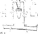
Fig. 1 is a plane, and expression is in conjunction with the shell of the handheld cordless phone of the not packed battery of first embodiment of the present invention,
Fig. 2 is the view along the II-II cross section of Fig. 1,
Fig. 3 is the part zoomed-in view in conjunction with Fig. 2 of the present invention,
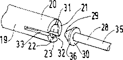
Fig. 4 is jockey the perspective view before connection of expression according to second embodiment of the invention,
Among Fig. 5, the plane of the device in the A presentation graphs 4, B-B cross section and the C-C cross section of B and C presentation graphs 5A,
Fig. 6 is the VI-VI sectional view of Fig. 5, and
Fig. 7 is the broken-open perspective view that locks together the device similar to device among Fig. 4 that assembles by two attaching parts.
Fig. 1 and Fig. 2 represent the shell 1 of handheld cordless phone, this shell forms by two attaching parts are connected together, one of them attaching parts is called anterior 2, another attaching parts are called back 3, this only just can see in Fig. 1, in the top 4 of mobile phone, be provided with rigidity locking element (not shown), be used in a known way two attaching parts 2 and 3 being locked together, described rigidity locking element works together by means of a groove of interaction position on the attaching parts corresponding with the elongated osculum of outer casing bottom.In order to realize the locking of attaching parts from this half-open position, be provided with jockey of the present invention, described jockey can see that this position is corresponding to the groove on the back 3 among Fig. 1 and Fig. 25 in the bottom that battery of mobile phone covers the shell 1 at place, position.
Described two devices are positioned at side, and comprise separately one with the anterior 2 fastening female component that link to each other 6 with one with the back 3 fastening convex parts that link to each other 7.It should be noted that parts 6 and 7 are to make with attaching parts mold pressing simultaneously separately, pressing preferably adopts acrylonitrile-butadiene-styrene terpolymer (ABS) to make.Should also be noted that convex part 7 and female component 6 are not directly to firmly fix on the sidewall that is connected to its attaching parts, and, should be fixedly attached to the bottom of attaching parts at least for female component 6.
Fig. 3 obtains after part among Fig. 28 is amplified six times, can observe jockey from this figure better.Female component has two elasticity uncinuses 11 and 12, it is oppositely arranged symmetrically, the space of determining between uncinus can be pushed open gradually by convex part 7, and in this case, convex part 7 is rod members that utilize two end to link to each other with attaching parts 3.Described two spaces comprise that first of a toroidal inserts space 13 and second space 14 that is called grasping part, the first horn mouth shape of inserting space 13 is the V-shape opening that forms at its place, both ends, ends in second space 14 and insert the space.13 and 14 intersection is provided with two by its concavity shoulder 15 and 16 uncinuses of determining in the space.Convex part 7 has an insertion end 17, as shown in Figure 3, it is big that this insertion end 17 upwards becomes gradually from the bottom, and the size of parts 7 is corresponding with the size of horn mouth 13, can embed in the horn mouth 13 when it is inserted into for the first time with box lunch, attaching parts are locked together.At an upper portion thereof, convex part 7 ends at a general shoulder 18 of this convex part.
Or rather, Fig. 1 is that the jig that the uncinus 11 and 12 by symmetry forms constitutes to embodiments of the invention shown in Figure 3.Shaft-like convex part 7 extends on the plane of symmetry of uncinus 11 and 12 substantially, with uncinus 11 with 12 vertical vertical, and its cross section forms a circular arc downwards, is coupled together by the end of a string with this circular arc on the cross section, and this string is equivalent to described shoulder.Best, general shoulder 18 is formed by two flat pieces of withdrawing slightly, it has the inclination angle identical with the direction in space 13, when owing to bar 7 13 passes when locking to space 14 from the space, make parts 7 have and better prevent the effect returned or the effect of similar harpoon for shoulder 15 and 16, because each flat pieces and contacting of shoulder 15 or 16 reduce into respectively in Fig. 3 section a bit, rather than line is so can provide more fastening connection between parts 6 and 7 when impacting.
For various embodiment of the present invention, provide the method for dismounting of attaching parts.To embodiment shown in Figure 3, after the battery of telephone device (mobile phone) has been removed, can more easily touch jockey for above-mentioned Fig. 1.In order to remove parts 6 and 7, as long as or preferably for this reason and the instrument of design takes off the free end of uncinus 11 and 12 with hand.For the ease of dismounting, the free end of uncinus 11 and 12 shape of honking is prolonged.
The required power of locking that realizes jockey should remain in the rational limit.The number of this power and these jockeys is also proportional with the rigidity of the uncinus 11 of female component 6 and 12 simultaneously.Effective length that can be by changing uncinus and/changing described rigidity by changing them perpendicular to the thickness on Fig. 2 and 3 in-planes.
Jockey according to second embodiment of the present invention is preferably used in the electronic installation bigger than mobile phone, that is, and and the middle-sized device shown in Fig. 4 to 7.It has the of the present invention essential characteristic identical with first embodiment, that is:
Convex part 28 comprises: one and insertion space 23 corresponding insertion ends 29, this insertion end 29 broadens gradually till it arrives a general shoulder of convex part 30.
More precisely, the embodiment of Fig. 4 to 7 is made of a circular casing 19, and this sleeve pipe 19 has three by longitudinal fluting 31,31,33 separated uncinuses 20,21,22.First inserts space 23 is truncated cone shape, and second grasping part 24 is cylindrical.Convex part 28 is made of a claw connector 35 with conical end 36.
The profile of the plane of Fig. 5 A and Fig. 5 B, 5C and Fig. 6 is represented the specific detail of second embodiment of the invention.Clearly (referring to Fig. 5), tapered end 36 and first insert space 23 and have the essentially identical small base of diameter, and the big base of end 36 is bigger than total pedestal in space 23, and two truncated cone shapes 23 and 36 also have essentially identical height.On the other hand, according to first modification, can be as seen from Figure 6, the diameter of the major diameter of end 36 and second grasping part 24 is basic identical.Therefore, (not shown) after parts 19 and 28 interconnect securely, shoulder 30 without any lateral clearance withstand shoulder 25,26 and 27, and when not impacting, uncinus 20,21 and 22 can radially outwards not promoted.The same with first embodiment shown in Fig. 1 to 3, making shoulder 30 withdraw for improving this convex shoulder slightly is useful to the locking of female shoulders 25,26 and 27.The rigidity that should also be noted that uncinus 20,21 and 22 is to strengthen by their curve shape, and described curve shape plays the effect of ribs.Similar to first embodiment, length that can be by changing uncinus and/diameter with sleeve pipe 19 of constant radial thickness changes described rigidity, if described length is long and/or described diameter is less then can judge that rigidity is relatively poor.
Fig. 7 represents another modification of second embodiment of the invention, and the convex part 28 of wherein said device is connected with 41 with their attaching parts 40 respectively after being loaded into female component 39.Should be noted that in the figure second space 43 ends at the outside of first attaching parts 41.And then this second space has the flaring shape that outwards broadens gradually, and for mold pressing sleeve pipe 39, and is the same with its support unit 41, needs the inclination angle in several years.This horn mouth shape can be used for by a proper implements device being taken apart.The shape of this instrument and convex part 28 are complementary, but size is bigger, when operation, make it pass second space 43, so that shift out the end of the uncinus of female component 39 gradually, be released out until tapered end 36, the head of instrument can continue sleeve pipe extrapolated, connects so that throw off fully.
The present invention is not limited only to the foregoing description.Notice in second embodiment camber parts 28 and the attaching parts 40 of Fig. 7 and make by ABS plastic usually, and preferably make by common mold pressing.Yet convex part 28 can be designed to an independent hardware, and securely is connected on plastics or the metal connecting piece in any known mode by its pedestal.A kind of modification in back for example can be connected to wheel hub cover on the wheel hub of a wheel it.
The present invention can reduce the screw that is used to be fastenedly connected two attaching parts, even saves fully for this purpose and the screw that adopts, in addition, for second embodiment, can take attaching parts apart from the outside at an easy rate.
Claims (7)
1, a kind of jockey comprises:
One has recessed shape parts that insert a space and a grasping part, forms at least two female shoulders on the interface between described insertion space and the grasping part;
A convex part that connects described female component, described convex part has an insertion end and the general shoulder of convex; It is characterized in that,
The general shoulder of described convex tilts along the direction towards described insertion end, described female shoulders also tilts a little along identical direction, thereby the contact when described insertion end is inserted in the described grasping part between general shoulder of described convex and the described female shoulders is reduced to a point.
2, jockey as claimed in claim 1 is characterized in that, described female component has with respect to the jig of a symmetry in the face of two uncinuses that claim by one and constitutes; And, longitudinally extending described convex part perpendicular to described uncinus on the described plane of symmetry has a cross section, its shape constitutes on the planes of withdrawal at the circular arc of its insertion portion and two slightly by one, and this plane of withdrawing slightly is at the relative part of its insertion portion complementation and form the general shoulder of described convex part.
3, be used for honeycomb or cordless portable part or be used for the attaching parts of infrared remote controller, it is characterized in that, comprise at least two jockeys as claimed in claim 2, it can touch below the detachable battery of described mobile phone or remote controller.
4, jockey as claimed in claim 1, it is characterized in that, described female component constitutes for columniform sleeve pipe substantially by one, and comprise at least three uncinuses of being separated by longitudinal fluting, described first space forms a truncated cone shape and one of described second space formation is cylindrical; And form convex part by a claw connector with tapering point.
5, jockey as claimed in claim 4 is characterized in that, second space of described female component broadens gradually towards the outside of described first attaching parts.
6, be used to comprise the attaching parts of the electronic installation of at least two jockeys as claimed in claim 5.
As each described jockey in the claim 1,2,4,5, it is characterized in that 7, described convex part is a hardware.
Applications Claiming Priority (2)
| Application Number | Priority Date | Filing Date | Title |
|---|---|---|---|
| FR97/15028 | 1997-11-28 | ||
| FR9715028 | 1997-11-28 |
Publications (2)
| Publication Number | Publication Date |
|---|---|
| CN1219465A CN1219465A (en) | 1999-06-16 |
| CN1096351C true CN1096351C (en) | 2002-12-18 |
Family
ID=9513957
Family Applications (1)
| Application Number | Title | Priority Date | Filing Date |
|---|---|---|---|
| CN98122943A Expired - Fee Related CN1096351C (en) | 1997-11-28 | 1998-11-27 | Joining device for firmly joining plastic joining parts together |
Country Status (7)
| Country | Link |
|---|---|
| US (1) | US6382867B2 (en) |
| EP (1) | EP0919734B1 (en) |
| JP (1) | JPH11254448A (en) |
| KR (1) | KR100572701B1 (en) |
| CN (1) | CN1096351C (en) |
| DE (1) | DE69826812T2 (en) |
| ES (1) | ES2230655T3 (en) |
Families Citing this family (14)
| Publication number | Priority date | Publication date | Assignee | Title |
|---|---|---|---|---|
| DE29920025U1 (en) | 1999-11-15 | 2000-03-30 | Trw Automotive Safety Sys Gmbh | Device for fastening an airbag module to a steering wheel |
| GB2357546B (en) | 1999-12-21 | 2003-08-27 | Nokia Mobile Phones Ltd | Housing assembly for portable electronic apparatus |
| US6688583B2 (en) * | 2000-01-03 | 2004-02-10 | Tmc, Inc. | Fence post finials |
| JP4861048B2 (en) * | 2006-04-27 | 2012-01-25 | 本田技研工業株式会社 | Seat support structure |
| DE202006009036U1 (en) * | 2006-06-08 | 2006-11-16 | Schleich Gmbh | Resting connection for building block shaped play system, includes base and structural units, where resting unit of structural units has projection with bulge diameter and resting unit of base units has bar shaped projection at opening wall |
| JP5020726B2 (en) * | 2007-07-06 | 2012-09-05 | ナイルス株式会社 | Locking structure between two members |
| US7843688B2 (en) * | 2008-06-25 | 2010-11-30 | Nokia Corporation | Latching mechanisms for portable electronic devices |
| TW201135087A (en) * | 2010-04-06 | 2011-10-16 | Giga Byte Tech Co Ltd | Coupling structure for shell |
| FR2975453B1 (en) * | 2011-05-18 | 2014-10-31 | Legrand France | MECHANICAL ASSEMBLY OF PRESS BUTTON TYPE AND APPLICATION TO ELECTRICAL EQUIPMENT |
| JP5938978B2 (en) * | 2012-03-23 | 2016-06-22 | 市光工業株式会社 | Mounting structure for vehicle parts |
| US9897330B2 (en) | 2013-05-29 | 2018-02-20 | Whirlpool Corporation | System and method for mounting undercabinet ventilation hood |
| US10018365B2 (en) | 2013-05-29 | 2018-07-10 | Whirlpool Corporation | System and method for mounting undercabinet ventilation hood |
| DE102015205427A1 (en) * | 2015-03-25 | 2016-09-29 | Robert Bosch Gmbh | Connecting element for mechanically connecting electronic housings |
| US10975618B2 (en) * | 2017-07-26 | 2021-04-13 | Whole Space Industries Ltd | Slat tilt mechanism for window coverings |
Citations (3)
| Publication number | Priority date | Publication date | Assignee | Title |
|---|---|---|---|---|
| US4726705A (en) * | 1985-09-27 | 1988-02-23 | Daniel Gomes | Knock down pivot fastener |
| EP0337227A2 (en) * | 1988-04-14 | 1989-10-18 | Leybold Aktiengesellschaft | Method of making a displacer for the cold finger of a cryogenic refrigerator and displacer made according to this method |
| FR2656165A1 (en) * | 1989-12-19 | 1991-06-21 | Fiat Auto Spa | Tool for disconnecting (unhooking) an electrical connector |
Family Cites Families (25)
| Publication number | Priority date | Publication date | Assignee | Title |
|---|---|---|---|---|
| US437004A (en) * | 1890-09-23 | Alfred j | ||
| FR360591A (en) * | 1905-03-02 | 1906-04-26 | Jean Sebastien Mariani | Snap button |
| US1200223A (en) * | 1916-01-03 | 1916-10-03 | Alexander Nathan | Snap-fastener. |
| US1823229A (en) * | 1930-03-10 | 1931-09-15 | Balbaud Paul | Separable fastener |
| US2832943A (en) * | 1954-12-09 | 1958-04-29 | Cutler Morris | Detachable coupling |
| US2946612A (en) * | 1958-02-24 | 1960-07-26 | Amerock Corp | Self-alining catch |
| GB1441640A (en) * | 1973-11-08 | 1976-07-07 | Zimmer Orthopaedic Ltd | Hand grip |
| DE2547909C3 (en) * | 1975-10-25 | 1979-05-10 | Gebr. Happich Gmbh, 5600 Wuppertal | Coat hooks for sliding arrangement on the handle formation of handles to be arranged in vehicles |
| US4324549A (en) * | 1978-11-13 | 1982-04-13 | Madray George W | Assembly for attaching a dental prosthesis to teeth |
| US4634004A (en) * | 1984-12-11 | 1987-01-06 | Empak Inc. | Magnetic tape security housing |
| US4616953A (en) * | 1985-09-27 | 1986-10-14 | Daniel Gomes | Knock down pivot fastener |
| JPS62299625A (en) * | 1986-06-18 | 1987-12-26 | Matsushita Electric Works Ltd | Frame-type foot warmer |
| JPS6395936A (en) * | 1986-10-13 | 1988-04-26 | Kasai Kogyo Co Ltd | Manufacture of automotive sun-visor |
| AU662740B2 (en) * | 1991-03-15 | 1995-09-14 | Square D Company | Protective snap-together enclosure for current transformers |
| DE9109552U1 (en) * | 1991-08-01 | 1991-09-12 | Siemens Ag, 8000 Muenchen, De | |
| FR2685015B1 (en) * | 1991-12-12 | 1994-04-01 | Staubli Verdol Sa | QUICK ATTACHMENT FOR CONNECTING AT LEAST ONE FUNICULAR ELEMENT TO THE END OF A CORD. |
| JPH05209611A (en) * | 1992-01-30 | 1993-08-20 | Eiko Shioda | Freely removable clamp |
| JP3435206B2 (en) * | 1994-03-29 | 2003-08-11 | ペンタックス株式会社 | Member connection structure |
| US5536917A (en) * | 1994-06-23 | 1996-07-16 | Motorla, Inc. | Housing with integral thin film resistive snap-fits |
| EP0695073A1 (en) * | 1994-07-29 | 1996-01-31 | Landis & Gyr Technology Innovation AG | Telephone handset |
| DE4439272A1 (en) * | 1994-11-03 | 1996-05-09 | Siemens Matsushita Components | Electrical capacitor, in particular electrolytic capacitor |
| US5807012A (en) * | 1995-07-31 | 1998-09-15 | Motorola, Inc. | Coupling apparatus |
| CA2184800C (en) * | 1995-09-26 | 2000-06-27 | Nicholas Mischenko | Radiotelephone handset having a removable, latching faceplate to accommodate a plurality of distinctive telephone appearances |
| CA2185374C (en) * | 1995-11-09 | 2000-01-25 | Trevor J. Aggus | Telephone base including visual display module |
| US5899824A (en) * | 1997-02-12 | 1999-05-04 | Accudart Corporation | Snap-fit dart and adapter |
-
1998
- 1998-11-18 EP EP98203910A patent/EP0919734B1/en not_active Expired - Lifetime
- 1998-11-18 DE DE69826812T patent/DE69826812T2/en not_active Expired - Fee Related
- 1998-11-18 ES ES98203910T patent/ES2230655T3/en not_active Expired - Lifetime
- 1998-11-24 US US09/198,928 patent/US6382867B2/en not_active Expired - Lifetime
- 1998-11-26 KR KR1019980051025A patent/KR100572701B1/en not_active IP Right Cessation
- 1998-11-27 JP JP10336927A patent/JPH11254448A/en not_active Abandoned
- 1998-11-27 CN CN98122943A patent/CN1096351C/en not_active Expired - Fee Related
Patent Citations (3)
| Publication number | Priority date | Publication date | Assignee | Title |
|---|---|---|---|---|
| US4726705A (en) * | 1985-09-27 | 1988-02-23 | Daniel Gomes | Knock down pivot fastener |
| EP0337227A2 (en) * | 1988-04-14 | 1989-10-18 | Leybold Aktiengesellschaft | Method of making a displacer for the cold finger of a cryogenic refrigerator and displacer made according to this method |
| FR2656165A1 (en) * | 1989-12-19 | 1991-06-21 | Fiat Auto Spa | Tool for disconnecting (unhooking) an electrical connector |
Also Published As
| Publication number | Publication date |
|---|---|
| EP0919734B1 (en) | 2004-10-06 |
| CN1219465A (en) | 1999-06-16 |
| US6382867B2 (en) | 2002-05-07 |
| ES2230655T3 (en) | 2005-05-01 |
| JPH11254448A (en) | 1999-09-21 |
| EP0919734A1 (en) | 1999-06-02 |
| KR100572701B1 (en) | 2006-09-27 |
| US20010051071A1 (en) | 2001-12-13 |
| DE69826812T2 (en) | 2005-10-06 |
| DE69826812D1 (en) | 2004-11-11 |
| KR19990045615A (en) | 1999-06-25 |
Similar Documents
| Publication | Publication Date | Title |
|---|---|---|
| CN1096351C (en) | Joining device for firmly joining plastic joining parts together | |
| AU2007200480B2 (en) | Clamping and articulation element | |
| US7028393B2 (en) | Contraction tool | |
| CN1133822C (en) | Tack for fixing button | |
| WO2019054627A1 (en) | Method for manufacturing coupler for joining reinforcing bars | |
| EP1951969B1 (en) | A connector apparatus for releasably connecting together two components, such as a newel post and a newel base, and method | |
| US20020039856A1 (en) | Flat cable connector with additional lead-fixing nodules | |
| CN101265937A (en) | Self locking combination nut | |
| US6001294A (en) | Method of manufacturing a screw connector | |
| CN205888936U (en) | Pliers | |
| CN210092509U (en) | Concentrator with column clamping and fixing structure | |
| JP2003269423A (en) | Fastener for connecting plates | |
| US7052224B2 (en) | Fastener assembly with molded internal helical flutes | |
| CN208706962U (en) | Anti-condensation connecting terminal | |
| CN207425969U (en) | A kind of power battery structure | |
| US11759941B1 (en) | Dead blow hammer | |
| CN212314320U (en) | Solid wood furniture fixing device | |
| US7033231B2 (en) | Radial screw connecting device for an electrical wire | |
| CN219054216U (en) | Elastic sleeve tool | |
| CN215343042U (en) | Clamping position rotation-proof terminal | |
| US20170155221A1 (en) | Double-side and dual-purpose connector | |
| CN220596034U (en) | Anti-blocking vibration disc | |
| US20020068479A1 (en) | Tangless terminal fixed lock | |
| CN217582787U (en) | Magnetic pin screw | |
| CN215762634U (en) | Locking rod and rod connecting structure |
Legal Events
| Date | Code | Title | Description |
|---|---|---|---|
| C06 | Publication | ||
| PB01 | Publication | ||
| C10 | Entry into substantive examination | ||
| SE01 | Entry into force of request for substantive examination | ||
| C14 | Grant of patent or utility model | ||
| GR01 | Patent grant | ||
| C19 | Lapse of patent right due to non-payment of the annual fee | ||
| CF01 | Termination of patent right due to non-payment of annual fee |