CN109570759B - Thin-wall cylinder longitudinal seam laser welding flexible holding device and weld extrusion force control method - Google Patents
Thin-wall cylinder longitudinal seam laser welding flexible holding device and weld extrusion force control method Download PDFInfo
- Publication number
- CN109570759B CN109570759B CN201910040948.2A CN201910040948A CN109570759B CN 109570759 B CN109570759 B CN 109570759B CN 201910040948 A CN201910040948 A CN 201910040948A CN 109570759 B CN109570759 B CN 109570759B
- Authority
- CN
- China
- Prior art keywords
- belt
- power
- shaft
- sides
- holding
- Prior art date
- Legal status (The legal status is an assumption and is not a legal conclusion. Google has not performed a legal analysis and makes no representation as to the accuracy of the status listed.)
- Expired - Fee Related
Links
- 238000003466 welding Methods 0.000 title claims abstract description 65
- 238000001125 extrusion Methods 0.000 title claims abstract description 38
- 238000000034 method Methods 0.000 title claims abstract description 18
- 230000007246 mechanism Effects 0.000 claims abstract description 52
- 230000005540 biological transmission Effects 0.000 claims abstract description 9
- 238000004519 manufacturing process Methods 0.000 abstract description 6
- 230000008859 change Effects 0.000 description 4
- 230000008569 process Effects 0.000 description 4
- 238000010586 diagram Methods 0.000 description 3
- 239000002131 composite material Substances 0.000 description 2
- 230000035515 penetration Effects 0.000 description 2
- 238000003825 pressing Methods 0.000 description 2
- 229910001220 stainless steel Inorganic materials 0.000 description 2
- 239000010935 stainless steel Substances 0.000 description 2
- 239000011324 bead Substances 0.000 description 1
- 230000009286 beneficial effect Effects 0.000 description 1
- 230000007547 defect Effects 0.000 description 1
- 230000006872 improvement Effects 0.000 description 1
- 238000007373 indentation Methods 0.000 description 1
- 238000009434 installation Methods 0.000 description 1
- 239000000463 material Substances 0.000 description 1
- 239000002184 metal Substances 0.000 description 1
- 230000004048 modification Effects 0.000 description 1
- 238000012986 modification Methods 0.000 description 1
- 230000001360 synchronised effect Effects 0.000 description 1
Images




Classifications
-
- B—PERFORMING OPERATIONS; TRANSPORTING
- B23—MACHINE TOOLS; METAL-WORKING NOT OTHERWISE PROVIDED FOR
- B23K—SOLDERING OR UNSOLDERING; WELDING; CLADDING OR PLATING BY SOLDERING OR WELDING; CUTTING BY APPLYING HEAT LOCALLY, e.g. FLAME CUTTING; WORKING BY LASER BEAM
- B23K26/00—Working by laser beam, e.g. welding, cutting or boring
- B23K26/20—Bonding
- B23K26/21—Bonding by welding
-
- B—PERFORMING OPERATIONS; TRANSPORTING
- B23—MACHINE TOOLS; METAL-WORKING NOT OTHERWISE PROVIDED FOR
- B23K—SOLDERING OR UNSOLDERING; WELDING; CLADDING OR PLATING BY SOLDERING OR WELDING; CUTTING BY APPLYING HEAT LOCALLY, e.g. FLAME CUTTING; WORKING BY LASER BEAM
- B23K26/00—Working by laser beam, e.g. welding, cutting or boring
- B23K26/70—Auxiliary operations or equipment
- B23K26/702—Auxiliary equipment
Landscapes
- Engineering & Computer Science (AREA)
- Physics & Mathematics (AREA)
- Optics & Photonics (AREA)
- Plasma & Fusion (AREA)
- Mechanical Engineering (AREA)
- Laser Beam Processing (AREA)
- Lining Or Joining Of Plastics Or The Like (AREA)
Abstract
本发明公开了一种薄壁筒体纵缝激光焊柔性抱紧装置,属于激光焊接技术领域。该装置包括动力传动机构、横向进给机构、柔性圆周抱紧机构和辅助支撑机构。左右两侧通过第一伺服电机自动调节皮带动力轴带动柔性抱紧带,使被焊工件全长度范围内获得圆周等效径向抱紧力,实现焊接接头无间隙配合;柔性生产,提高生产效率,降低工装投入成本。本发明还公开了一种采用上述柔性抱紧装置的焊缝挤压力控制方法,通过第一伺服电机、第二伺服电机的启动配合,利用压力传感器感应工件抱紧压力,实现焊接过程中,焊缝两侧可以获得等效可控挤压力,从而提高了焊缝强度。
The invention discloses a flexible holding device for laser welding of longitudinal seams of a thin-walled cylinder, which belongs to the technical field of laser welding. The device includes a power transmission mechanism, a transverse feeding mechanism, a flexible circumferential gripping mechanism and an auxiliary supporting mechanism. The left and right sides automatically adjust the belt power shaft to drive the flexible clamping belt through the first servo motor, so that the circular equivalent radial clamping force can be obtained within the entire length of the welded workpiece, and the welding joints can be matched without gaps; flexible production, improve production efficiency , reduce tooling input costs. The invention also discloses a welding seam extrusion force control method using the above-mentioned flexible holding device. Equivalent controllable extrusion force can be obtained on both sides of the weld, thereby increasing the strength of the weld.
Description
技术领域technical field
本发明属于激光焊接技术领域,特别是涉及一种薄壁筒体纵缝激光焊柔性抱紧装置及焊缝挤压力控制方法。The invention belongs to the technical field of laser welding, and in particular relates to a flexible holding device for laser welding of a thin-walled cylindrical longitudinal seam and a method for controlling the extrusion force of the welding seam.
背景技术Background technique
薄壁筒体通常指材质为3系和4系不锈钢,壁厚在0.5mm至2.0mm之间,管径在φ100mm至φ600mm之间;纵缝焊接指板材通过卷压或冲压成形后对其纵缝进行焊接;该项技术主要应用于汽车零部件、家电、食品机械和医疗机械等领域。Thin-walled cylinder usually refers to the material of 3 series and 4 series stainless steel, the wall thickness is between 0.5mm and 2.0mm, and the pipe diameter is between φ100mm and φ600mm; Seams are welded; this technology is mainly used in the fields of auto parts, home appliances, food machinery and medical machinery.
薄壁筒体纵缝激光焊焊缝强度与焊接接头间隙及焊缝挤压力大小有着直接关系。由于不锈钢板材屈服强度高,经成形后回弹导致焊接接头存3mm至8mm缝隙。目前,主要采用在纵焊前增加点焊工序或专用工装进行焊接。纵焊接前增加点焊工序对焊接接头间隙控制精度低,激光焊质量不稳定,且后续纵缝焊接依靠上压板压紧,焊缝无径向挤压力,焊缝强度低。专用工装有两种形式:一种是待焊管件经液压推力将工件推送到封闭外导圈通道内,管件被逐渐退出外导圈后焊接,这种方式虽然增加了焊缝挤压力的,但受工件成形尺寸精度影响,无法控制接头间隙和焊缝挤压力大小。外导圈作为专用夹具,制造精度高,投入成本高;工装通用性差,无法实现柔性生产。另一种是半活动激光直缝焊装置,中半国专利号CN201520625164.3,名称为“一种薄壁管件激光直缝焊接装置”,公开日:2015年12月9日。该专利公开了薄壁管件激光直缝焊接方法,通过采用半活动半随形定位装置来进行对缝压紧和焊接。夹具不完全随形造成焊接过程中产品变形和表面划伤;由于待焊工件中间存在缝隙,在半活动工装中焊缝两侧无法获得等效挤压力,带来如焊缝超高、错边、叠边或未焊透等了诸多问题需要解决。There is a direct relationship between the weld strength of the thin-walled cylinder longitudinal seam laser welding and the gap of the welded joint and the extrusion force of the weld. Due to the high yield strength of the stainless steel sheet, the springback after forming results in a gap of 3mm to 8mm in the welded joint. At present, welding is mainly carried out by adding a spot welding process or special tooling before longitudinal welding. Adding a spot welding process before longitudinal welding has low control accuracy for the gap of the welded joint, and the quality of laser welding is unstable, and the subsequent longitudinal seam welding relies on the upper pressure plate to be pressed, the weld has no radial extrusion force, and the weld strength is low. There are two types of special tooling: one is that the pipe fittings to be welded push the workpiece into the closed outer guide ring channel by hydraulic thrust, and the pipe fittings are gradually withdrawn from the outer guide ring and then welded. Although this method increases the welding seam extrusion force, However, affected by the dimensional accuracy of the workpiece forming, it is impossible to control the joint gap and the welding seam extrusion force. As a special fixture, the outer guide ring has high manufacturing precision and high investment cost; the tooling has poor versatility and cannot achieve flexible production. The other is a semi-active laser straight seam welding device, with the Chinese Patent No. CN201520625164.3, titled "A Laser Straight Seam Welding Device for Thin-walled Pipe Fittings", published on December 9, 2015. This patent discloses a laser straight seam welding method for thin-walled pipe fittings, which uses a semi-movable and semi-conformal positioning device to press and weld the seam. The incomplete conformity of the fixture results in product deformation and surface scratches during the welding process; due to the gap between the workpieces to be welded, the equivalent extrusion force cannot be obtained on both sides of the weld in the semi-movable tooling, resulting in such as super high weld and misalignment. Edges, overlapping edges, or lack of penetration are a number of issues that need to be addressed.
因此,亟需一种薄壁筒纵缝激光焊柔性抱紧装置,保证焊接接头在全长度范围内无间隙配合,从而满足筒体激光焊接接头间隙要求;同时需要一种基于该装置的焊缝等效挤压力控制方法,实现对焊缝两侧施加等效挤压力,有效控制焊缝挤压力,从而提高薄壁筒体纵缝激光焊焊缝强度。Therefore, there is an urgent need for a thin-walled cylindrical longitudinal seam laser welding flexible clamping device to ensure that the welded joints are matched with no gaps in the full length range, so as to meet the gap requirements of the cylindrical laser welded joints; at the same time, a welding seam based on the device is needed. The equivalent extrusion force control method realizes the application of equivalent extrusion force on both sides of the weld, effectively controls the extrusion force of the weld, and thus improves the strength of the thin-walled cylindrical longitudinal seam laser welding seam.
发明内容SUMMARY OF THE INVENTION
本发明的目的在于提供一种薄壁筒体纵缝激光焊柔性抱紧装置,能够解决薄壁筒体纵缝激光焊接接头在全长度范围内无间隙配合问题和柔性生产问题。同时,本发明还提出一种采用上述柔性抱紧装置的焊缝挤压力控制方法,解决焊接过程中如何使焊缝两侧获得等效挤压力以及如何控制焊缝挤压力的问题。The purpose of the present invention is to provide a thin-walled cylindrical longitudinal seam laser welding flexible holding device, which can solve the problem of no gap fit and flexible production of the thin-walled cylindrical longitudinal seam laser welded joint in the entire length range. At the same time, the present invention also proposes a welding seam extrusion force control method using the above-mentioned flexible holding device, which solves the problems of how to obtain equivalent extrusion force on both sides of the weld seam and how to control the welding seam extrusion force during the welding process.
本发明所采用的技术方案是提供一种薄壁筒体纵缝激光焊柔性抱紧装置,包括动力连杆机构、横向进给机构、柔性圆周抱紧机构和辅助支撑机构,所述动力连杆机构、横向进给机构和柔性圆周抱紧机构均对称设置。The technical scheme adopted by the present invention is to provide a thin-walled cylindrical body longitudinal seam laser welding flexible holding device, which includes a power link mechanism, a transverse feed mechanism, a flexible circumferential holding mechanism and an auxiliary support mechanism. The mechanism, the transverse feed mechanism and the flexible circumferential gripping mechanism are all symmetrically arranged.
所述动力连杆机构包括连杆、第二伺服电机、第一连接板、第二连接板、连接座、连接销轴、摇杆、传动销轴、动力连接盘、动力轴、轴承和轴承座;所述第一连接板与第二连接板之间设置有动力轴,所述动力轴一端连接轴承,所述轴承位于轴承座内,所述轴承座固定在第二连接板上;所述动力轴的另一端连接第二伺服电机,所述第二伺服电机固定在第一连接板上;所述动力轴通过动力连接盘与摇杆一端连接,所述摇杆的另一端通过传动销轴与连杆的一端连接,所述连杆的另一端通过连接销轴与连接座连接。The power linkage mechanism includes a connecting rod, a second servo motor, a first connecting plate, a second connecting plate, a connecting seat, a connecting pin, a rocker, a transmission pin, a power connecting plate, a power shaft, a bearing and a bearing seat A power shaft is arranged between the first connecting plate and the second connecting plate, one end of the power shaft is connected to a bearing, the bearing is located in the bearing seat, and the bearing seat is fixed on the second connecting plate; the power The other end of the shaft is connected to the second servo motor, which is fixed on the first connecting plate; the power shaft is connected to one end of the rocker through the power connection plate, and the other end of the rocker is connected to the rocker through the transmission pin shaft. One end of the connecting rod is connected, and the other end of the connecting rod is connected with the connecting seat through the connecting pin.
进一步地,所述横向进给机构包括支架、固定连接板、运动臂、固定轴块和导向轴;所述导向轴穿过运动臂的运动槽,通过固定轴块固定在两个支架之间;所述运动臂底部设置有固定连接板;所述支架固定在底板上。Further, the lateral feeding mechanism includes a bracket, a fixed connecting plate, a moving arm, a fixed shaft block and a guide shaft; the guide shaft passes through the movement groove of the moving arm and is fixed between the two brackets through the fixed shaft block; The bottom of the moving arm is provided with a fixed connection plate; the bracket is fixed on the bottom plate.
进一步地,所述柔性圆周抱紧机构包括第一伺服电机、皮带动力轴、轴套、托件衬垫、皮带导向板、压力传感器和抱紧带;所述皮带动力轴置于运动臂的轴孔中,皮带动力轴的一端连接第一伺服电机,另一端与轴套连接;所述第一伺服电机、轴套分别固定在运动臂的两端;所述皮带导向板固定在运动臂顶部,所述压力传感器置于皮带导向板的端部;所述运动臂中每两道立筋之间设置有抱紧带,所述抱紧带贴合在两块皮带导向板上表面,抱紧带的两端分别与双侧的皮带动力轴固定连接;所述托件衬垫放置于位于两块皮带导向板之间的抱紧带上。Further, the flexible circumferential gripping mechanism includes a first servo motor, a belt power shaft, a shaft sleeve, a support pad, a belt guide plate, a pressure sensor and a gripping belt; the belt power shaft is placed on the shaft of the moving arm. In the hole, one end of the belt power shaft is connected to the first servo motor, and the other end is connected to the shaft sleeve; the first servo motor and the shaft sleeve are respectively fixed on both ends of the moving arm; the belt guide plate is fixed on the top of the moving arm, The pressure sensor is placed at the end of the belt guide plate; a holding belt is arranged between every two vertical ribs in the moving arm, and the holding belt is attached to the surface of the two belt guide plates, and the holding belt is The two ends of the belt are respectively fixedly connected with the belt power shafts on both sides; the support pad is placed on the holding belt between the two belt guide plates.
进一步地,所述辅助支撑机构包括底板、支撑座和芯轴;所述支撑座位于两块皮带导向板之间,且与底板固定连接;所述芯轴一端固定在支撑座上,所述芯轴与皮带导向板平行。Further, the auxiliary support mechanism includes a bottom plate, a support seat and a mandrel; the support seat is located between two belt guide plates and is fixedly connected to the bottom plate; one end of the mandrel is fixed on the support seat, and the core The shaft is parallel to the belt guide plate.
进一步地,所述压力传感器与计算机信号连接。Further, the pressure sensor is connected with a computer signal.
本发明还提供了一种采用薄壁筒体纵缝激光焊柔性抱紧装置的焊缝挤压力控制方法,包括以下步骤:The invention also provides a welding seam extrusion force control method using a thin-walled cylinder longitudinal seam laser welding flexible holding device, comprising the following steps:
S1,将待焊的工件套在芯轴上;S1, sleeve the workpiece to be welded on the mandrel;
S2,启动双侧的第二伺服电机,使得两个第二伺服电机的电机轴同时由外向内转动,实现动力连杆机构带动横向进给机构同时向芯轴运动,当运动到工件圆周抱紧轨迹上时,关闭第二伺服电机;S2, start the second servo motors on both sides, so that the motor shafts of the two second servo motors rotate from the outside to the inside at the same time, so that the power link mechanism drives the transverse feed mechanism to move toward the mandrel at the same time. When on the track, turn off the second servo motor;
S3,启动双侧的第一伺服电机,使得两个第一伺服电机的电机轴同时由内向外转动,进而带动两侧的皮带动力轴同时由内向外旋转运动,抱紧带沿着左右皮带导向板向外侧滑动并缠绕在两侧的皮带动力轴上,工件被逐渐抱紧并获得圆周径向压力;随着抱紧带两端不断地被缠绕在皮带动力轴上,抱紧带被拉紧,抱紧力不断增加;作用在压力传感器上的反作用力也在不断增加;S3, start the first servo motors on both sides, so that the motor shafts of the two first servo motors rotate from the inside to the outside at the same time, and then drive the belt power shafts on both sides to rotate from the inside to the outside at the same time, and the holding belt is guided along the left and right belts The plate slides to the outside and is wound on the belt power shaft on both sides, the workpiece is gradually tightened and obtains circumferential radial pressure; as the two ends of the holding belt are continuously wound on the belt power shaft, the holding belt is tightened , the holding force is increasing; the reaction force acting on the pressure sensor is also increasing;
S4,启动计算机中的焊缝挤压力测试程序,当被测压力值大于额定压力值时,双侧的第一伺服电机的电机轴同时由外向内旋转,双侧的皮带动力轴相向运动,抱紧带变松,焊缝挤压力降低;当被测压力值小于额定压力值时,双侧的第一伺服电机的电机轴同时由内向外旋转,双侧的皮带动力轴反向运动,抱紧带被拉紧,工件抱紧力增加,焊缝挤压力不断提高直至达到额定压力值后,关闭第一伺服电机;S4, start the welding seam extrusion force test program in the computer. When the measured pressure value is greater than the rated pressure value, the motor shafts of the first servo motors on both sides rotate from the outside to the inside at the same time, and the belt power shafts on both sides move toward each other. The tightening belt becomes loose, and the extrusion force of the weld is reduced; when the measured pressure value is less than the rated pressure value, the motor shafts of the first servo motors on both sides rotate from the inside to the outside at the same time, and the power shafts of the belts on both sides move in the opposite direction. When the clamping belt is tightened, the clamping force of the workpiece increases, and the extrusion force of the welding seam continues to increase until the rated pressure value is reached, and the first servo motor is turned off;
S5,焊接;S5, welding;
S6,焊接结束后,再启动两侧的第一伺服电机,使得第一伺服电机的电机轴同时由外向内转动,带动两侧的皮带动力轴同时由外向内转动,使得抱紧带松开工件;S6, after the welding is completed, start the first servo motors on both sides, so that the motor shafts of the first servo motors rotate from outside to inside at the same time, and drive the belt power shafts on both sides to rotate from outside to inside at the same time, so that the tightening belt loosens the workpiece ;
S7,取出焊后的工件。S7, take out the workpiece after welding.
本发明的有益效果是:The beneficial effects of the present invention are:
1.采用对称结构设计,双侧同步相向进给,同时突破传统刚性夹紧方式,采用复合材料抱紧工件,可以随着产品外形尺寸变化而变化,通过对筒体施加均匀圆周径向抱紧力,解决了接头错边、叠边问题,从而实现薄壁筒体纵缝激光焊接接头在全长度范围内无间隙配合。1. The symmetrical structure design is adopted, and the two sides are synchronously fed toward each other. At the same time, it breaks through the traditional rigid clamping method. The composite material is used to hold the workpiece, which can change with the change of the product size. By applying a uniform circumferential radial hold to the cylinder It solves the problem of joint misalignment and overlapping, so as to realize the gap-free fit of the thin-walled cylindrical longitudinal seam laser welded joint in the whole length range.
2.通过柔性抱紧装置和压力传感器结合,自动调整焊缝两侧挤压力,根据产品对焊缝挤压力不同要求,自动调节,获得最佳等效挤压力,提高焊缝强度。2. Through the combination of the flexible holding device and the pressure sensor, the extrusion force on both sides of the weld is automatically adjusted. According to the different requirements of the product for the extrusion force of the weld, it is automatically adjusted to obtain the best equivalent extrusion force and improve the strength of the weld.
附图说明Description of drawings
为了更清楚地说明本发明实施例或现有技术中的技术方案,下面将对实施例或现有技术描述中所需要使用的附图作简单地介绍,显而易见地,下面描述中的附图仅仅是本发明的一些实施例,对于本领域普通技术人员来讲,在不付出创造性劳动的前提下,还可以根据这些附图获得其他的附图。In order to explain the embodiments of the present invention or the technical solutions in the prior art more clearly, the following briefly introduces the accompanying drawings that need to be used in the description of the embodiments or the prior art. Obviously, the accompanying drawings in the following description are only These are some embodiments of the present invention. For those of ordinary skill in the art, other drawings can also be obtained according to these drawings without creative efforts.
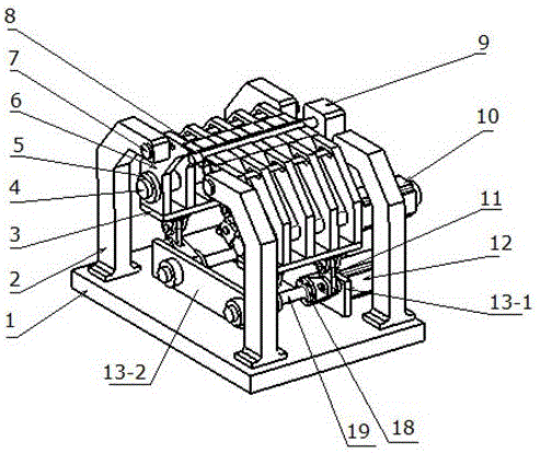
图1是本发明装置的整体结构示意图。FIG. 1 is a schematic diagram of the overall structure of the device of the present invention.
图2是本发明的抱紧带与工件关系示意图。FIG. 2 is a schematic diagram of the relationship between the tightening belt and the workpiece of the present invention.
图3是本发明的动力传动机构分解示意图。3 is an exploded schematic view of the power transmission mechanism of the present invention.
图4是本发明的横向传动机构分解示意图。Figure 4 is an exploded schematic view of the transverse transmission mechanism of the present invention.
图5是本发明的柔性圆周抱紧机构分解示意图。Fig. 5 is an exploded schematic view of the flexible circumferential gripping mechanism of the present invention.
图6是压力传感器安装位置示意图。Figure 6 is a schematic diagram of the installation position of the pressure sensor.
图7是本发明焊缝挤压力控制方法的流程图。FIG. 7 is a flow chart of the welding seam extrusion force control method of the present invention.
图中,1.底板;2.支架;3.固定连接板;4.皮带动力轴;5.轴套;6.运动臂;7.固定轴块 ;8.导向轴 ;9.支撑座;10.第一伺服电机;11.连杆;12.第二伺服电机;13-1.第一连接板;13-2.第二连接板;14.连接座;15.连接销轴;16.摇杆;17.传动销轴;18.动力连接盘;19.动力轴;20.轴承;21.轴承座;22.芯轴;23.托件衬垫;24.皮带导向板;25.压力传感器;26.抱紧带;27.工件。In the figure, 1. Bottom plate; 2. Bracket; 3. Fixed connection plate; 4. Belt power shaft; 5. Shaft sleeve; 6. Movement arm; 7. Fixed shaft block; 8. Guide shaft; 9. Support seat; 10 1. The first servo motor; 11. The connecting rod; 12. The second servo motor; 13-1. The first connecting plate; 13-2. The second connecting plate; 14. The connecting seat; 15. The connecting pin; Rod; 17. Drive pin; 18. Power connection plate; 19. Power shaft; 20. Bearing; 21. Bearing seat; 22. Mandrel; ; 26. Hold the belt; 27. Workpiece.
具体实施方式Detailed ways
下面将结合本发明实施例中的附图,对本发明实施例中的技术方案进行清楚、完整地描述,显然,所描述的实施例仅仅是本发明一部分实施例,而不是全部的实施例。基于本发明中的实施例,本领域普通技术人员在没有做出创造性劳动前提下所获得的所有其他实施例,都属于本发明保护的范围。The technical solutions in the embodiments of the present invention will be clearly and completely described below with reference to the accompanying drawings in the embodiments of the present invention. Obviously, the described embodiments are only a part of the embodiments of the present invention, but not all of the embodiments. Based on the embodiments of the present invention, all other embodiments obtained by those of ordinary skill in the art without creative efforts shall fall within the protection scope of the present invention.
参照附图1。本发明公开了一种薄壁筒体纵缝激光焊柔性抱紧装置,包括动力连杆机构、横向进给机构、柔性圆周抱紧机构和辅助支撑机构;动力连杆机构、横向进给机构和柔性圆周抱紧机构均对称设置。Refer to Figure 1. The invention discloses a flexible clamping device for longitudinal seam laser welding of thin-walled cylinders, comprising a power link mechanism, a transverse feed mechanism, a flexible circumferential clamping mechanism and an auxiliary support mechanism; The flexible circumferential holding mechanisms are symmetrically arranged.
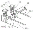
参照附图3。动力连杆机构包括连杆11、第二伺服电机12、第一连接板13-1、第二连接板13-2、连接座14、连接销轴15、摇杆16、传动销轴17、动力连接盘18、动力轴19、轴承20和轴承座21;第一连接板13-1与第二连接板13-2之间设置有动力轴19,动力轴19一端连接轴承20,轴承20位于轴承座21内,轴承座21固定在第二连接板13-2上;动力轴19的另一端连接第二伺服电机12,第二伺服电机12固定在第一连接板13-1上;动力轴19通过动力连接盘18与摇杆16一端连接,摇杆16的另一端通过传动销轴17与连杆11的一端连接,连杆11的另一端通过连接销轴15与连接座14连接。Refer to Figure 3. The power linkage mechanism includes a connecting
参照附图4。横向进给机构包括支架2、固定连接板3、运动臂6、固定轴块7和导向轴8;导向轴8穿过运动臂6的运动槽,通过固定轴块7固定在两个支架2之间;运动臂6底部设置有固定连接板3;支架2固定在底板1上。Refer to Figure 4. The transverse feed mechanism includes a
参照附图5和附图6。柔性圆周抱紧机构包括第一伺服电机10、皮带动力轴4、轴套5、托件衬垫23、皮带导向板24、压力传感器25和抱紧带26;皮带动力轴4置于运动臂6的轴孔中,皮带动力轴4的一端连接第一伺服电机10,另一端与轴套5连接;第一伺服电机10、轴套5分别固定在运动臂6的两端;皮带导向板24固定在运动臂6顶部,压力传感器25置于皮带导向板的端部;运动臂6中每两道立筋之间设置有抱紧带26,抱紧带26贴合在两块皮带导向板24上表面,抱紧带26的两端分别与双侧的皮带动力轴4固定连接;托件衬垫23放置于位于两块皮带导向板24之间的抱紧带26上。同时,抱紧带26将反作用力施加给压力传感器25,可以时时反馈挤压力信息,对焊缝两侧实施可控的等效挤压力。Refer to Figure 5 and Figure 6. The flexible circumferential gripping mechanism includes a
参照附图2。辅助支撑机构包括底板1、支撑座9和芯轴22;支撑座9位于两块皮带导向板24之间,且与底板1固定连接;芯轴22一端固定在支撑座9上,呈悬臂状态,用于取、放件的支撑作用。芯轴22与皮带导向板24平行。压力传感器25与计算机信号连接。Refer to Figure 2. The auxiliary support mechanism includes a base plate 1, a
为了使工件两侧受力均匀,动力连杆机构、横向进给机构和柔性圆周抱紧机构均采用对称结构设计,实现双侧同步相向进给。In order to make the force on both sides of the workpiece evenly, the power link mechanism, the lateral feed mechanism and the flexible circumferential clamping mechanism are all designed with a symmetrical structure to achieve synchronous feeding on both sides.
为了实现快速切换产品规格,突破传统刚性夹紧方式,采用复合材料抱紧带抱紧工件,可以随着产品外形尺寸变化而变化,满足不同规格产品使用,提高生产效率,降低工装费用,同时非金属与工件表面接触,不会对工件外观产生划痕或压痕。In order to quickly switch product specifications and break through the traditional rigid clamping method, composite material holding belts are used to hold the workpiece tightly, which can change with the change of product dimensions to meet the use of products of different specifications, improve production efficiency, and reduce tooling costs. The metal is in contact with the surface of the workpiece without scratches or indentations on the appearance of the workpiece.
对了保证筒体全长度范围内焊接接头无间隙配合,通过多条抱紧带双向同时进给,对筒体施加圆周均匀径向抱紧力。In order to ensure that the welded joints within the full length of the cylinder body have no gaps, the cylinder is fed with a uniform circumferential radial clamping force through multiple clamping belts that are fed in both directions at the same time.
本发明装置的工作原理如下:The working principle of the device of the present invention is as follows:
将待焊工件放置在芯轴22上,启动双侧的第二伺服电机12,使得两个第二伺服电机12的电机轴同时由外向内转动,实现动力连杆机构带动横向进给机构同时向芯轴22运动,动力连杆机构带动横向进给机构同时向中间运动到设定位置(即工件圆周抱紧轨迹上),关闭第二伺服电机12。启动双侧第一伺服电机10,使得两个第一伺服电机10的电机轴同时由内向外转动,进而带动两侧的皮带动力轴4同时由内向外旋转运动,抱紧带26沿着左右皮带导向板24向外滑动并缠绕在两侧皮带动力轴4上,工件27被逐渐抱紧并获得圆周径向压力;随着抱紧带26两端不断地被缠绕在皮带动力轴4上,抱紧力不断增加,同时作用在压力传感器上的反作用力也在不断增加。The workpiece to be welded is placed on the mandrel 22, and the
参照附图7。启动计算机中的焊缝挤压力测试程序,通过压力传感器25测得抱紧带26两侧反压力值,由于该反压力值与焊缝两侧挤压力值相等,所以当被测压力值(即焊缝两侧挤压力值)大于额定压力值时,通过第一伺服电机控制器控制双侧的第一伺服电机10的电机轴同时由外向内旋转,双侧的皮带动力轴4相向运动,抱紧带26松开,焊缝挤压力降低;当被测压力值小于额定压力值时,通过第一伺服电机控制器控制双侧的第一伺服电机10的电机轴同时由内向外旋转,双侧的皮带动力轴4反向运动,抱紧带26被拉紧,工件27抱紧力增加,焊缝挤压力不断提高直至达到额定压力值后第一伺服电机10停止工作,设备开始焊接,焊接后,再启动两侧的第一伺服电机10,使得第一伺服电机10的电机轴同时由外向内转动,带动两侧的皮带动力轴4同时由外向内转动,使得抱紧带26松开工件27。Refer to Figure 7. Start the welding seam extrusion force test program in the computer, and measure the back pressure value on both sides of the holding
本发明还公开了一种采用上述柔性抱紧装置的焊缝等效挤压力控制方法,包括以下步骤:The invention also discloses a method for controlling the equivalent extrusion force of the welding seam using the above-mentioned flexible holding device, comprising the following steps:
S1,将待焊的工件27套在芯轴22上;S1, the
S2,启动双侧的第二伺服电机12,使得两个第二伺服电机12的电机轴同时由外向内转动,实现动力连杆机构带动横向进给机构同时向芯轴22运动,当运动到工件27圆周抱紧轨迹上时,关闭第二伺服电机12;S2, start the
S3,启动双侧的第一伺服电机10,使得两个第一伺服电机10的电机轴同时由内向外转动,进而带动两侧的皮带动力轴4同时由内向外旋转运动,抱紧带26沿着左右皮带导向板24向外侧滑动并缠绕在两侧的皮带动力轴4上,工件27被逐渐抱紧并获得圆周径向压力;随着抱紧带26两端不断地被缠绕在皮带动力轴上,抱紧带26被拉紧,抱紧力不断增加;作用在压力传感器25上的反作用力也在不断增加;S3, start the
S4,启动计算机中的焊缝挤压力测试程序,当被测压力值大于额定压力值时,双侧的第一伺服电机10的电机轴同时由外向内旋转,双侧的皮带动力轴4相向运动,抱紧带26变松,焊缝挤压力降低;当被测压力值小于额定压力值时,双侧的第一伺服电机10的电机轴同时由内向外旋转,双侧的皮带动力轴4反向运动,抱紧带26被拉紧,工件27抱紧力增加,焊缝挤压力不断提高直至达到额定压力值后,关闭第一伺服电机10;S4, start the welding seam extrusion force test program in the computer, when the measured pressure value is greater than the rated pressure value, the motor shafts of the
S5,焊接;S5, welding;
S6,焊接结束后,再启动两侧的第一伺服电机10,使得第一伺服电机10的电机轴同时由外向内转动,带动两侧的皮带动力轴4同时由外向内转动,使得抱紧带26松开工件27;S6, after the welding is completed, start the
S7,取出焊后的工件27。S7, take out the
通过有效控制焊缝两侧挤压力大小,使焊缝两侧获得最佳等效挤压力,解决焊缝错边、未焊透、焊道高、焊缝收缩槽等焊缝质量缺陷,提高焊接强度。By effectively controlling the extrusion force on both sides of the weld, the best equivalent extrusion force on both sides of the weld can be obtained, and the quality defects of the weld such as misalignment, incomplete penetration, high weld bead, and weld shrinkage groove can be solved. Improve weld strength.
以上所述仅为本发明的较佳实施例而已,并非用于限定本发明的保护范围。凡在本发明的精神和原则之内所作的任何修改、等同替换、改进等,均包含在本发明的保护范围内。The above descriptions are only preferred embodiments of the present invention, and are not intended to limit the protection scope of the present invention. Any modification, equivalent replacement, improvement, etc. made within the spirit and principle of the present invention are included in the protection scope of the present invention.
Claims (6)
Priority Applications (1)
| Application Number | Priority Date | Filing Date | Title |
|---|---|---|---|
| CN201910040948.2A CN109570759B (en) | 2019-01-16 | 2019-01-16 | Thin-wall cylinder longitudinal seam laser welding flexible holding device and weld extrusion force control method |
Applications Claiming Priority (1)
| Application Number | Priority Date | Filing Date | Title |
|---|---|---|---|
| CN201910040948.2A CN109570759B (en) | 2019-01-16 | 2019-01-16 | Thin-wall cylinder longitudinal seam laser welding flexible holding device and weld extrusion force control method |
Publications (2)
| Publication Number | Publication Date |
|---|---|
| CN109570759A CN109570759A (en) | 2019-04-05 |
| CN109570759B true CN109570759B (en) | 2020-07-10 |
Family
ID=65915006
Family Applications (1)
| Application Number | Title | Priority Date | Filing Date |
|---|---|---|---|
| CN201910040948.2A Expired - Fee Related CN109570759B (en) | 2019-01-16 | 2019-01-16 | Thin-wall cylinder longitudinal seam laser welding flexible holding device and weld extrusion force control method |
Country Status (1)
| Country | Link |
|---|---|
| CN (1) | CN109570759B (en) |
Families Citing this family (2)
| Publication number | Priority date | Publication date | Assignee | Title |
|---|---|---|---|---|
| CN112247381B (en) * | 2020-08-21 | 2022-08-16 | 长春理工大学 | Guiding preheating and stress-relieving dynamic shape correcting device for thin-wall cylinder laser welding longitudinal joint |
| CN114309949B (en) * | 2022-01-13 | 2024-10-22 | 大匠激光科技(苏州)有限公司 | Round tube laser welding device |
Family Cites Families (11)
| Publication number | Priority date | Publication date | Assignee | Title |
|---|---|---|---|---|
| CN2333479Y (en) * | 1998-05-05 | 1999-08-18 | 庞林华 | Square frame chain pipeline welding clamp |
| CN100423882C (en) * | 2006-11-16 | 2008-10-08 | 华中科技大学 | A welding fixture for welding cylinders |
| CN200967129Y (en) * | 2006-11-16 | 2007-10-31 | 华中科技大学 | Welding assembly jaw for welding cylinder |
| CN100554743C (en) * | 2008-06-04 | 2009-10-28 | 哈尔滨工程大学 | One-piece Remote Pipe Flange Bolting Tool |
| CN101758352B (en) * | 2009-11-17 | 2012-02-08 | 武汉法利普纳泽切割系统有限公司 | Longitudinal-seam laser welding positioning device for thin-wall circular tube |
| CN202411624U (en) * | 2011-12-08 | 2012-09-05 | 成都焊研科技有限责任公司 | Tunnel type full-automatic straight seam welding machine |
| CN203221315U (en) * | 2013-05-07 | 2013-10-02 | 济南力波焊接设备制造有限公司 | Barrel straight seam welding machine keyboard hold-down mechanism |
| CN204171580U (en) * | 2014-11-05 | 2015-02-25 | 重庆拓泰汽车零部件有限公司 | A kind of stack shell joint weld machine |
| CN104874925B (en) * | 2015-06-05 | 2016-05-25 | 南昌航空大学 | A kind of ultra-thin-wall cylinder is with weldering flexible welding clamp device and using method thereof |
| CN206241495U (en) * | 2016-11-09 | 2017-06-13 | 江苏金鑫电器有限公司 | A kind of aluminium alloy longitudinal seam automatic welding connection device |
| CN208348661U (en) * | 2018-05-25 | 2019-01-08 | 廊坊华元机电工程有限公司 | Hydraulic locking apparatus for the construction of horizontal directional drill method Pipeline Crossing Program |
-
2019
- 2019-01-16 CN CN201910040948.2A patent/CN109570759B/en not_active Expired - Fee Related
Also Published As
| Publication number | Publication date |
|---|---|
| CN109570759A (en) | 2019-04-05 |
Similar Documents
| Publication | Publication Date | Title |
|---|---|---|
| CN106312320B (en) | A kind of thin-walled cylinder anti-deformation fixture and the laser melting coating machine for repairing crack | |
| CN110579164B (en) | Synchronous clamping eccentric detection device for round workpiece | |
| CN112247381B (en) | Guiding preheating and stress-relieving dynamic shape correcting device for thin-wall cylinder laser welding longitudinal joint | |
| CN106392451B (en) | A kind of inner support positioner for the welding of carrier rocket tank circular seam of flange | |
| CN108213829A (en) | A kind of staggeredly scalable tooling of spoke type and its adjusting method for agitating friction weldering | |
| CN212858407U (en) | Pipeline and flange welding frock | |
| CN119407439B (en) | A mechanical engineering thin-walled pipe automatic welding device and its use method | |
| CN212946323U (en) | Nonrust steel pipe welding equipment | |
| CN118875563A (en) | Steel plate butt welding equipment | |
| CN120382316A (en) | A pipeline welding robot | |
| JPH0953772A (en) | Connecting structure of stainless steel pipe and molding device of connecting end part | |
| KR101397939B1 (en) | Welding device | |
| CN118951550A (en) | A sheet metal welding device with automatic docking function and a method thereof | |
| CN113996915A (en) | Friction stir welding device with variable speed probe | |
| CN110653482A (en) | Friction stir welding rolling supporting structure | |
| CN109570759A (en) | Thin-wall barrel longitudinal joint Laser Welding flexibility cohesion device and weld seam squeeze force control method | |
| CN121514803A (en) | A welding device for hydraulic cylinder body welds | |
| CN210615662U (en) | A seam joint device and straight seam welding equipment | |
| CN219426016U (en) | Circular seam welding device | |
| CN119747981A (en) | Pipe on-site welding equipment | |
| CN219725130U (en) | Straight welded pipe welding seam deviation preventing device | |
| CN218946804U (en) | Welding frame for flange | |
| JPH0952128A (en) | Method for forming flange on end of stainless steel tube and device for working flange | |
| CN211331938U (en) | Welding platform clamping device | |
| CN104999190B (en) | Fixed seam expanding device and welding equipment for thin-walled plate cylinder |
Legal Events
| Date | Code | Title | Description |
|---|---|---|---|
| PB01 | Publication | ||
| PB01 | Publication | ||
| SE01 | Entry into force of request for substantive examination | ||
| SE01 | Entry into force of request for substantive examination | ||
| GR01 | Patent grant | ||
| GR01 | Patent grant | ||
| CF01 | Termination of patent right due to non-payment of annual fee |
Granted publication date: 20200710 Termination date: 20210116 |
|
| CF01 | Termination of patent right due to non-payment of annual fee |