CN109500168B - Section steel bending processing method - Google Patents
Section steel bending processing method Download PDFInfo
- Publication number
- CN109500168B CN109500168B CN201811388818.XA CN201811388818A CN109500168B CN 109500168 B CN109500168 B CN 109500168B CN 201811388818 A CN201811388818 A CN 201811388818A CN 109500168 B CN109500168 B CN 109500168B
- Authority
- CN
- China
- Prior art keywords
- section steel
- cylinder
- wheel
- bending
- steel
- Prior art date
- Legal status (The legal status is an assumption and is not a legal conclusion. Google has not performed a legal analysis and makes no representation as to the accuracy of the status listed.)
- Active
Links
Images


Classifications
-
- B—PERFORMING OPERATIONS; TRANSPORTING
- B21—MECHANICAL METAL-WORKING WITHOUT ESSENTIALLY REMOVING MATERIAL; PUNCHING METAL
- B21D—WORKING OR PROCESSING OF SHEET METAL OR METAL TUBES, RODS OR PROFILES WITHOUT ESSENTIALLY REMOVING MATERIAL; PUNCHING METAL
- B21D7/00—Bending rods, profiles, or tubes
- B21D7/08—Bending rods, profiles, or tubes by passing between rollers or through a curved die
-
- B—PERFORMING OPERATIONS; TRANSPORTING
- B21—MECHANICAL METAL-WORKING WITHOUT ESSENTIALLY REMOVING MATERIAL; PUNCHING METAL
- B21D—WORKING OR PROCESSING OF SHEET METAL OR METAL TUBES, RODS OR PROFILES WITHOUT ESSENTIALLY REMOVING MATERIAL; PUNCHING METAL
- B21D43/00—Feeding, positioning or storing devices combined with, or arranged in, or specially adapted for use in connection with, apparatus for working or processing sheet metal, metal tubes or metal profiles; Associations therewith of cutting devices
- B21D43/003—Positioning devices
-
- B—PERFORMING OPERATIONS; TRANSPORTING
- B21—MECHANICAL METAL-WORKING WITHOUT ESSENTIALLY REMOVING MATERIAL; PUNCHING METAL
- B21D—WORKING OR PROCESSING OF SHEET METAL OR METAL TUBES, RODS OR PROFILES WITHOUT ESSENTIALLY REMOVING MATERIAL; PUNCHING METAL
- B21D7/00—Bending rods, profiles, or tubes
- B21D7/14—Bending rods, profiles, or tubes combined with measuring of bends or lengths
-
- B—PERFORMING OPERATIONS; TRANSPORTING
- B21—MECHANICAL METAL-WORKING WITHOUT ESSENTIALLY REMOVING MATERIAL; PUNCHING METAL
- B21D—WORKING OR PROCESSING OF SHEET METAL OR METAL TUBES, RODS OR PROFILES WITHOUT ESSENTIALLY REMOVING MATERIAL; PUNCHING METAL
- B21D7/00—Bending rods, profiles, or tubes
- B21D7/16—Auxiliary equipment, e.g. for heating or cooling of bends
Landscapes
- Engineering & Computer Science (AREA)
- Mechanical Engineering (AREA)
- Bending Of Plates, Rods, And Pipes (AREA)
Abstract
Description
技术领域technical field
本发明涉及型钢冷弯成型技术,尤其是型钢冷弯成型的设备。The invention relates to the technology of cold-bending of section steel, in particular to the equipment of cold-bending of section steel.
背景技术Background technique
本发明的顶拉式型钢弯曲机主要用来弯曲工字钢、H型钢等型钢。型钢包括相对设置的前端板、后端板和连接在前端板和后端板之间的中间板。The top-pull type section steel bending machine of the present invention is mainly used for bending section steels such as I-beam and H-beam. The section steel includes a front end plate, a rear end plate and a middle plate connected between the front end plate and the rear end plate.
现有的型钢弯曲机是由主电机、摆线针轮减速器、滚轮、油泵电机、齿轮油泵、溢流阀、电磁换向阀、工作油缸、顶轮及油箱等部件组成,把型钢放在弯曲机上,型钢与摆线针轮减速器带动的滚轮接触后,启动电机油泵组,由电动油泵输出的高压油经溢流阀(可调整所需压力),进入电液阀,由电液阀和点动开关(点进、点退)控制油缸工作,工作油缸推进,将型钢与三个支撑滚轮压紧并在未发生弯曲变形时开始计算,油缸推进的长度进程为每次10mm-15mm,开主电机正转或反转,由主电机带动型钢工作,反复操作,达到所需半径为止。但这些型钢弯曲机在弯曲较小半径时容易造成型钢局部不可控变形和弯曲较大截面型钢时因局部受力过大容易造成型钢不可控变形,主要是造成型钢中间薄板不可控变形,无法满足使用要求。The existing section steel bending machine is composed of main motor, cycloidal pinwheel reducer, roller, oil pump motor, gear oil pump, relief valve, electromagnetic reversing valve, working oil cylinder, top wheel and oil tank. On the bending machine, after the section steel contacts the roller driven by the cycloidal pinwheel reducer, the motor oil pump unit is started, and the high-pressure oil output by the electric oil pump enters the electro-hydraulic valve through the relief valve (the required pressure can be adjusted), and the electro-hydraulic valve is driven by the electro-hydraulic valve. And the jog switch (point in, point back) to control the work of the oil cylinder, the working oil cylinder is advanced, the section steel and the three support rollers are pressed tightly and the calculation starts when there is no bending deformation. The length of the cylinder advancing is 10mm-15mm each time. Turn on the main motor for forward or reverse rotation, and the main motor drives the section steel to work, and repeat the operation until the required radius is reached. However, these section steel bending machines are likely to cause uncontrollable local deformation of the section steel when bending a small radius and uncontrollable deformation of the section steel due to excessive local force when bending a large section steel, mainly causing uncontrollable deformation of the middle sheet of the section steel, which cannot meet the Requirements.
弯曲度是指长条轧件(型、棒、管材)在长度方向上的弯曲程度。每米长度上弯曲的弦高为每米弯曲度;总长度弯曲的总弦高同总长度的比为总弯曲度。现有的型钢弯曲机在弯曲型钢时不能实时调节型钢的弯曲程度,一般需要弯曲多次,才能将型钢的弯曲度控制到预定目标,不能在弯曲过程中根据实际的弯曲效果对弯曲机构进行调整。Bending degree refers to the bending degree of the long strip (shape, bar, pipe) in the length direction. The bending chord height per meter of length is the bending degree per meter; the ratio of the total chord height bending over the total length to the total length is the total bending degree. The existing section steel bending machine cannot adjust the bending degree of the section steel in real time when bending the section steel. Generally, it needs to be bent several times to control the bending degree of the section steel to the predetermined target, and the bending mechanism cannot be adjusted according to the actual bending effect during the bending process. .
发明内容SUMMARY OF THE INVENTION
本发明的目的在于提出一种型钢弯曲加工方法,避免型钢弯曲时因受力不均和缺少限位而容易造成型钢局部不可控变形而无法满足使用要求的问题。The purpose of the present invention is to propose a bending processing method of profiled steel, which avoids the problem that the profiled steel is easily deformed locally uncontrollably due to uneven force and lack of limit during bending and cannot meet the requirements of use.
本发明所加工的型钢包括相对设置的前端板、后端板和连接在前端板和后端板之间的中间板。The profiled steel processed by the present invention includes a front end plate, a rear end plate and a middle plate connected between the front end plate and the rear end plate.
为实现上述目的,本发明的型钢弯曲加工方法通过顶拉式型钢弯曲机进行;顶拉式型钢弯曲机包括型钢限位输送机构、型钢双向同步弯曲装置和弯曲度测量装置;In order to achieve the above object, the section steel bending processing method of the present invention is carried out by a top-pull section steel bending machine; the top-pull section steel bending machine includes a section steel limit conveying mechanism, a section steel two-way synchronous bending device and a curvature measuring device;
型钢限位输送机构包括工作台,工作台的右端为型钢的上料端,工作台的左端为型钢的下料端;工作台左端部设有用于驱动型钢的左驱动装置,工作台右端部设有用于驱动型钢的右驱动装置;左驱动装置和右驱动装置之间的工作台上左右间隔设有若干用于承托矫正型钢的矫正限位装置;工作台左右方向的中部位置设有用于在垂直于型钢长度方向上对型钢施加弯曲力的所述型钢双向同步弯曲装置;型钢双向同步弯曲装置在左右方向上位于两个矫正限位装置之间;The section steel limit conveying mechanism includes a workbench, the right end of the workbench is the feeding end of the section steel, and the left end of the workbench is the unloading end of the section steel; the left end of the workbench is provided with a left drive device for driving the section steel, and the right end of the workbench is provided There is a right drive device for driving the section steel; a number of correction limit devices for supporting the correction section steel are arranged at the left and right intervals on the worktable between the left drive device and the right drive device; The profiled steel bidirectional synchronous bending device for exerting bending force on the profiled steel in a direction perpendicular to the length of the profiled steel;
型钢双向同步弯曲装置包括固定连接在工作台上的支撑架,支撑架顶部沿前后方向平行并排固定设有两道上导轨,支撑架底部沿前后方向平行并排固定设有两道下导轨;支撑架中部前后相对设有顶轮箱和拉轮箱,顶轮箱位于拉轮箱正前方,顶轮箱和拉轮箱的顶部均与上导轨滑动配合且二者的底部均与下导轨滑动配合;顶轮箱内转动连接有顶轮,拉轮箱内上下间隔转动连接有上拉轮和下拉轮,上拉轮和下拉轮之间的间隙与型钢的中间板厚度相适配;上拉轮和下拉轮均用于向后紧压型钢的后端板,顶轮用于向后紧压型钢的前端板;支撑架后部通过拉缸安装座安装有拉缸液压缸,支撑架前部通过顶缸安装座安装有顶缸液压缸,拉缸液压缸的伸出杆铰接有拉缸连接座,拉缸连接座与拉轮箱固定连接;顶缸液压缸的伸出杆铰接有顶缸连接座,顶缸连接座与顶轮箱固定连接;顶轮后端与拉轮后端之间的距离与型钢宽度相适配;The profile steel bidirectional synchronous bending device includes a support frame fixedly connected to the worktable. The top of the support frame is fixed with two upper guide rails in parallel and side by side along the front and rear directions, and the bottom of the support frame is fixed with two lower guide rails in parallel along the front and rear directions. There are a top wheel box and a pull wheel box opposite to the front and back, the top wheel box is located in front of the pull wheel box, the tops of the top wheel box and the pull wheel box are slidingly matched with the upper guide rail, and the bottoms of both are slidingly matched with the lower guide rail; The top pulley is rotatably connected in the wheel box, and the upper pulley and the lower pulley are rotatably connected up and down in the pull wheel box. The wheels are used to press the rear end plate of the section steel backward, and the top wheel is used to press the front end plate of the section steel backward; the rear part of the support frame is installed with a pull cylinder hydraulic cylinder through the pull cylinder mounting seat, and the front part of the support frame passes through the top cylinder. The mounting seat is installed with a top cylinder hydraulic cylinder, the extension rod of the pull cylinder hydraulic cylinder is hinged with a pull cylinder connection seat, and the pull cylinder connection seat is fixedly connected with the pull wheel box; the extension rod of the top cylinder hydraulic cylinder is hinged with a top cylinder connection seat, The top cylinder connecting seat is fixedly connected with the top wheel box; the distance between the rear end of the top wheel and the rear end of the pull wheel is adapted to the width of the section steel;
弯曲度测量装置包括横梁,横梁铰接在型钢限位输送机构的工作台的下料端部;横梁中部固定连接有弯曲度测量用位移传感器,弯曲度测量用位移传感器具有用于测量型钢拱高的伸缩测量杆,伸缩测量杆的自由端与型钢背离其圆心的一侧表面相接;弯曲度测量用位移传感器两侧的横梁上对称设有弦长杆,弦长杆的自由端与型钢背离其圆心的一侧表面相接;The bending degree measuring device includes a beam, and the beam is hinged at the unloading end of the worktable of the section steel limit conveying mechanism; the middle of the beam is fixedly connected with a displacement sensor for bending degree measurement, and the displacement sensor for bending degree measurement has a function for measuring the arch height of the section steel. The telescopic measuring rod, the free end of the telescopic measuring rod is connected with the surface of the side of the profiled steel away from the center of the circle; the beams on both sides of the displacement sensor for bending degree measurement are symmetrically provided with chord length rods, and the free end of the chord length rod is away from the profiled steel. One side of the center of the circle is in contact with each other;
顶轮箱内固定有竖向设置的顶轮轴,顶轮轴通过轴承连接所述顶轮;拉轮箱上部固定有竖向设置的上拉轮轴,拉轮箱下部固定有竖向设置的下拉轮轴;上拉轮轴通过轴承连接所述上拉轮,下拉轮轴通过轴承连接所述下拉轮;所述横梁与型钢限位输送机构的工作台之间连接有拉簧;所述弦长杆的自由端和伸缩测量杆的自由端均呈锥形,且尖端朝向型钢;左驱动装置和右驱动装置结构相同,均由上至下包括电动机、与电动机输出轴传动连接的减速器、自下而上与减速器输出轴相连接的联轴器以及用于通过摩擦力驱动型钢的主动轮,主动轮与被输送的型钢的后端板相压接;主动轮的轴自下而上与联轴器相连接;主动轮通过轴承安装于主动箱体上,主动箱体固定在工作台上;矫正限位装置包括中空的固定架,每套矫正限位装置的固定架在被输送的型钢前后两侧对称设有两套;每套矫正限位装置的两个固定架下部通过轴承安装有用于承托型钢的托辊,每套矫正限位装置的两个固定架上部设有用于限定型钢顶部位置的压辊;压辊通过轴承转动连接有滑动座,托辊通过轴承转动连接有固定座,固定座与固定架固定连接;滑动座向上固定连接有受力筒,受力筒内插设有调节丝杠,调节丝杠向上伸出固定架且其顶部连接有水平设置的把手;所述受力筒中部设有螺纹孔,所述调节丝杠与螺纹孔相应的部分设有环形凹槽,受力筒通过螺纹孔螺纹连接有定位螺栓,定位螺栓伸入所述环形凹槽;A vertically arranged top wheel shaft is fixed in the top wheel box, and the top wheel shaft is connected to the top wheel through a bearing; the upper part of the pull wheel box is fixed with a vertically arranged upper pull wheel axle, and the lower part of the pull wheel box is fixed with a vertically arranged pull down wheel shaft; The upper pulley shaft is connected to the upper pulley through a bearing, and the lower pulley shaft is connected to the lower pulley through a bearing; a tension spring is connected between the cross beam and the working table of the section steel limit conveying mechanism; the free end of the chord length rod and The free ends of the telescopic measuring rods are all tapered, and the tip faces the profile steel; the left drive device and the right drive device have the same structure, including a motor, a reducer connected to the motor output shaft from top to bottom, and a bottom-to-top and speed reducer. The coupling connected with the output shaft of the conveyor and the driving wheel used to drive the section steel by friction, the driving wheel is crimped with the rear end plate of the section steel being conveyed; the shaft of the driving wheel is connected with the coupling from bottom to top ;The driving wheel is installed on the driving box through the bearing, and the driving box is fixed on the worktable; the correction limit device includes a hollow fixing frame, and the fixing frame of each set of correction limit device is symmetrically arranged on the front and rear sides of the conveyed section steel. There are two sets; the lower parts of the two fixed frames of each set of correction limit devices are installed with rollers for supporting the profile steel through bearings, and the upper parts of the two fixed frames of each set of correction limit devices are provided with pressure rollers for limiting the top position of the profile steel ; The pressure roller is connected with a sliding seat through the bearing rotation, the idler is connected with a fixed seat through the bearing rotation, and the fixed seat is fixedly connected with the fixed frame; The adjusting screw extends upward from the fixing frame, and the top is connected with a horizontally arranged handle; the middle of the force-receiving cylinder is provided with a threaded hole, and the corresponding part of the adjusting screw and the threaded hole is provided with an annular groove, and the force-receiving cylinder passes through The threaded hole is threadedly connected with a positioning bolt, and the positioning bolt extends into the annular groove;
本发明的型钢弯曲加工方法按以下步骤进行:The section steel bending processing method of the present invention is carried out according to the following steps:
第一步骤是准备步骤;The first step is the preparation step;
先通过旋转把手,确保各压辊与托辊之间的距离大于型钢的前端板和后端板的高度;First, by rotating the handle, make sure that the distance between each pressing roller and the idler is greater than the height of the front end plate and the rear end plate of the section steel;
第二步骤是初始上料步骤;将型钢由左至右依次穿过各矫正限位装置以及所述型钢双向同步弯曲装置,使各矫正限位装置处的型钢由各矫正限位装置的压辊和托辊之间穿过,并使型钢双向同步弯曲装置处的型钢由上拉轮和下拉轮之间的间隙处穿过;使型钢的前端板向前与顶轮后端相接,使型钢的后端板向前与上拉轮和下拉轮的后端相接;然后,调节旋转把手,使压辊向下与型钢相接触;The second step is the initial feeding step; the profiled steel is passed through each correction limit device and the profile steel bidirectional synchronous bending device in turn from left to right, so that the profile steel at each correction limiter is pressed by the rollers of each correction limiter. Pass through between the roller and the idler, and make the section steel at the two-way synchronous bending device of section steel pass through the gap between the upper pulley and the lower pulley; make the front end plate of the section steel forward and connect with the rear end of the top wheel, so that the section steel The rear end plate of the upper and lower pulleys is forwardly connected to the rear ends of the upper pulley and the lower pulley; then, adjust the rotating handle so that the pressing roller contacts the profile steel downwards;
第三步骤是弯曲加工步骤;The third step is a bending step;
使拉缸液压缸和顶缸液压缸同步动作,拉缸液压缸的伸出杆通过拉缸连接座、拉轮箱、上拉轮轴和下拉轮轴带动上拉轮和下拉轮向后拉动型钢的后端板,顶缸液压缸的伸出杆通过顶缸连接座、顶轮箱、顶轮轴和顶轮向后顶压型钢的前端板,型钢由于其前端板和后端板同步受力而发生弯曲;The pulling cylinder hydraulic cylinder and the top cylinder hydraulic cylinder act synchronously. The end plate, the extension rod of the hydraulic cylinder of the top cylinder presses the front end plate of the profile steel backward through the top cylinder connecting seat, the top wheel box, the top wheel shaft and the top wheel, and the profile steel is bent due to the simultaneous force of its front end plate and the rear end plate. ;
同步启动左驱动装置和右驱动装置的电动机,电动机通过减速器、联轴器驱动主动轮旋转,主动轮通过摩擦力驱动型钢向左移动,移动中的型钢在通过型钢双向同步弯曲装置时由于其前端板和后端板同步受力而发生弯曲;弯曲后的型钢向左送出工作台。The motors of the left drive device and the right drive device are started synchronously. The motor drives the driving wheel to rotate through the reducer and the coupling. The driving wheel drives the profile steel to move to the left through friction. The front-end plate and the rear-end plate are simultaneously subjected to force to bend; the bent section steel is sent to the left of the workbench.
在第三步骤中还包括有弯曲度调整操作;弯曲度调整操作是:The third step also includes a curvature adjustment operation; the curvature adjustment operation is:
型钢在向左离开工作台时,拉簧能够通过自身的弹力自动拉动横梁,使弦长杆和伸缩测量杆均紧压在型钢上;When the section steel leaves the workbench to the left, the tension spring can automatically pull the beam through its own elastic force, so that the chord length rod and the telescopic measuring rod are pressed tightly on the section steel;
加工同一批次的型钢具有统一的目标弯曲度,目标弯曲度对应有预定拱高;加工过程中,通过弯曲度测量装置测量加工后型钢的实测拱高;The profile steel processed in the same batch has a uniform target curvature, and the target curvature corresponds to a predetermined arch height; during the processing, the measured arch height of the processed profile steel is measured by the curvature measuring device;
如果实测拱高低于预定拱高,说明型钢的弯曲程度低于目标弯曲度,此时对型钢双向同步弯曲装置进行调整,加大顶缸液压缸的伸出杆和拉缸液压缸的伸出杆的伸出量,从而增大型钢的弯曲程度;If the measured arch height is lower than the predetermined arch height, it means that the bending degree of the section steel is lower than the target bending degree. At this time, adjust the bidirectional synchronous bending device of the section steel, and increase the extension rod of the hydraulic cylinder of the top cylinder and the extension rod of the hydraulic cylinder of the pulling cylinder. The protrusion amount, thereby increasing the bending degree of the steel;
如果实测拱高高于预定拱高,说明型钢的弯曲程度高于目标弯曲度,此时对型钢双向同步弯曲装置进行调整,减少顶缸液压缸的伸出杆和拉缸液压缸的伸出杆的伸出量,从而减小型钢的弯曲程度;If the measured arch height is higher than the predetermined arch height, it means that the bending degree of the section steel is higher than the target bending degree. At this time, adjust the bidirectional synchronous bending device of the section steel to reduce the extension rod of the hydraulic cylinder of the top cylinder and the extension rod of the hydraulic cylinder of the pulling cylinder. The amount of protrusion, thereby reducing the bending degree of the steel;
通过弯曲度调整操作将型钢的弯曲度控制在目标弯曲度范围。Control the curvature of the section steel within the target curvature range through the curvature adjustment operation.
顶拉式型钢弯曲机还包括有电控装置,弯曲度测量用位移传感器、拉缸液压缸和顶缸液压缸分别连接电控装置;拉缸安装座上设有用于测量拉缸液压缸的伸出杆位移量的拉缸位移传感器,顶缸安装座上设有用于测量顶缸液压缸的伸出杆位移量的顶缸位移传感器,顶缸位移传感器和拉缸位移传感器分别连接电控装置;The top-pull type steel bending machine also includes an electric control device. The displacement sensor for bending degree measurement, the pull-cylinder hydraulic cylinder and the top-cylinder hydraulic cylinder are respectively connected to the electric control device; The pulling cylinder displacement sensor for the displacement of the outgoing rod, the top cylinder mounting seat is provided with a top cylinder displacement sensor for measuring the displacement of the extending rod of the top cylinder hydraulic cylinder, and the top cylinder displacement sensor and the pulling cylinder displacement sensor are respectively connected to the electric control device;
在进行弯曲度调整操作时,电控装置接收弯曲度测量用位移传感器的信号,相应调整顶缸液压缸的伸出杆和拉缸液压缸的伸出杆的伸出量;电控装置通过接收拉缸位移传感器和顶缸位移传感器的信号,对顶缸液压缸的伸出杆和拉缸液压缸的伸出杆的伸出量进行精确调整。During the bending adjustment operation, the electronic control device receives the signal of the displacement sensor for bending measurement, and adjusts the extension of the extension rod of the hydraulic cylinder of the top cylinder and the extension rod of the hydraulic cylinder of the pulling cylinder accordingly; The signals of the displacement sensor of the pulling cylinder and the displacement sensor of the top cylinder are used to precisely adjust the extension of the extension rod of the hydraulic cylinder of the head cylinder and the extension rod of the hydraulic cylinder of the pulling cylinder.
本发明的型钢弯曲加工方法工序安排紧凑高效,能够充分利用型钢限位输送机构对型钢的输送功能和限位功能,在型钢被弯曲的同时防止型钢局部变形过度,从而保证型钢品质。本发明的型钢弯曲加工方法通过上拉轮、下拉轮和顶轮,在保证滚动摩擦(滚动摩擦力较滑动摩擦力大大降低,从而节约能耗)力的前提下,对型钢两端同时进行拉和顶两个动作,在相较滑动摩擦减小型钢输送中的摩擦力的同时,使型钢受力更为均匀,与以往相比大幅降低了弯曲过程中发生不可控变形的概率。The profiled steel bending processing method of the present invention has compact and efficient process arrangement, can fully utilize the conveying function and the limiting function of the profiled steel limit conveying mechanism for the profiled steel, prevents the profiled steel from being excessively deformed locally while the profiled steel is bent, thereby ensuring the profiled steel quality. The section steel bending processing method of the present invention uses the upper pulley, the lower pulley and the top pulley, and under the premise of ensuring rolling friction (rolling friction is greatly reduced compared with sliding friction, thereby saving energy consumption), the two ends of the section steel are simultaneously pulled. Compared with the sliding friction, the two actions of Heding reduce the frictional force during the conveying of the section steel, and at the same time make the section steel more evenly stressed, which greatly reduces the probability of uncontrollable deformation during the bending process compared with the past.
不同型材具有不同的回弹性质,因此即便型钢双向同步弯曲装置的工作状态完全一样,用来加工不同型材,也会出现弯曲度不同的现象。本发明的型钢弯曲加工方法通过弯曲度测量装置能够实时监控型钢双向同步弯曲装置对型钢的实际弯曲效果,从而得以相应调整型钢双向同步弯曲装置,与以往缺少实时监测型钢弯曲度的技术相比,一次弯曲成型合格率高,提高了加工效率和加工精度。通过电控装置则提高了加工型钢的自动化程度,有利于提高加工效率和精度。Different profiles have different resilience properties, so even if the working state of the profiled steel bidirectional synchronous bending device is exactly the same, when used to process different profiles, the phenomenon of different bending degrees will occur. The section steel bending processing method of the present invention can monitor the actual bending effect of the section steel bidirectional synchronous bending device on the section steel in real time through the bending degree measuring device, so that the section steel bidirectional synchronous bending device can be adjusted accordingly. The qualified rate of one-time bending forming is high, which improves the processing efficiency and processing accuracy. Through the electronic control device, the automation degree of processing section steel is improved, which is beneficial to improve the processing efficiency and precision.
工作时,本发明中的顶缸液压缸和拉缸液压缸同步动作,顶缸液压缸向后顶压型钢(工字钢或H型钢)的前部,同时拉缸液压缸向后拉动型钢的后部,从而使型钢发生弯曲。型钢在弯曲过程中,前部和后部同时受力,因而受力更为均匀,与以往相比大幅降低了弯曲过程中发生不可控变形的概率,提高产品的合格率,在整体上提高产品的品质。When working, the hydraulic cylinder of the top cylinder and the hydraulic cylinder of the pull cylinder in the present invention act synchronously, and the hydraulic cylinder of the top cylinder presses the front part of the section steel (I-beam or H-section steel) backward, and at the same time, the pull-cylinder hydraulic cylinder pulls the back of the section steel. rear, so that the profile steel is bent. During the bending process of the section steel, the front and rear parts are stressed at the same time, so the force is more uniform, which greatly reduces the probability of uncontrollable deformation during the bending process compared with the past, improves the qualification rate of the product, and improves the product as a whole. quality.
左驱动装置和右驱动装置结构简单,便于安装,通过摆线针轮减速器可以降低主动轮的转速,控制型钢的前进速度。本发明通过主动轮与型钢后端板之间的摩擦力带动型钢运动,传动过程稳定可靠。型钢双向同步弯曲装置对型钢施加弯曲力时,矫正限位装置能够在输送型钢的过程中将型钢限定在预定位置,防止型钢局部变形过度、导致降低型钢品质甚至产生废品。The left driving device and the right driving device are simple in structure and easy to install, and the speed of the driving wheel can be reduced by the cycloidal pinwheel reducer to control the forward speed of the section steel. The invention drives the profile steel to move through the friction force between the driving wheel and the profile steel rear end plate, and the transmission process is stable and reliable. When the profiled steel bidirectional synchronous bending device exerts bending force on the profiled steel, the correction limit device can limit the profiled steel to a predetermined position during the process of conveying the profiled steel, preventing the profiled steel from being excessively deformed locally, resulting in a reduction in the quality of the profiled steel and even generation of waste products.
由于对型钢施加拉力或推力的是能够转动的轮子(上拉轮、下拉轮以及顶轮),因此能够一边向型钢施加弯曲变形力,同时使型钢连续不断地通过上拉轮、下拉轮以及顶轮向下游方向(图1所示的左向)运动,从而对经过型钢双向同步弯曲装置的型钢不断进行冷弯作业。Since it is the rotatable wheels (upper pulley, lower pulley and top pulley) that exert pulling or pushing force on the section steel, the bending deformation force can be applied to the section steel while the section steel continuously passes through the upper pulley, the lower pulley and the top pulley. The wheel moves in the downstream direction (leftward as shown in Figure 1), so that the cold-bending operation of the section steel passing through the section steel bidirectional synchronous bending device is continuously performed.
通过旋转把手,可以通过调节丝杠调节压辊所受到的压力,在保证限位作用的前提下尽可能减小压辊受到的压力可以降低压辊与型钢之间的摩擦力,从而降低型钢输送过程中的能耗。By rotating the handle, the pressure on the pressure roller can be adjusted by adjusting the lead screw, and the pressure on the pressure roller can be reduced as much as possible on the premise of ensuring the limiting effect, which can reduce the friction between the pressure roller and the profile steel, thereby reducing the profile steel conveying. energy consumption in the process.
环形凹槽的设置,使得定位螺栓不会妨碍调节丝杠的旋转,同时又使调节丝杠、定位螺栓和受力筒在上下方向上形成联动关系,使得调节丝杠的上下运动可以通过受力筒和滑动座转化为压辊的上下运动。如果没有定位螺栓和受力筒以及环形凹槽,则调节丝杠只能对压辊施加向下的压力,不能将压辊向上提起来。The annular groove is arranged so that the positioning bolt will not hinder the rotation of the adjusting screw, and at the same time, the adjusting screw, the positioning bolt and the force cylinder form a linkage relationship in the up and down direction, so that the up and down movement of the adjusting screw can pass the force The barrel and sliding seat are converted into the up and down movement of the pressure roller. If there is no positioning bolt, force cylinder and annular groove, the adjusting screw can only exert downward pressure on the pressure roller, and cannot lift the pressure roller upward.
本发明中的型钢双向同步弯曲装置安装在型钢限位输送机构的工作台上,位于型钢输送路径上,在型钢通过时不断进行冷弯作业,工作效率较高,产品质量较以往得到较大提升。The profiled steel bidirectional synchronous bending device in the present invention is installed on the workbench of the profiled steel limit conveying mechanism, and is located on the profiled steel conveying path. The cold bending operation is continuously performed when the profiled steel passes through, the work efficiency is high, and the product quality is greatly improved compared with the past. .
上导轨和下导轨不仅起到运动导向作用,还起到稳定箱体结构(包括顶轮箱和拉轮箱),防止因箱体变形影响上拉轮和下拉轮的相对位置关系的作用。The upper guide rail and the lower guide rail not only play the role of motion guidance, but also stabilize the box structure (including the top wheel box and the pull wheel box) to prevent the relative positional relationship between the upper pulley and the lower pulley due to the deformation of the box.
弯曲度测量装置能够在顶拉式型钢弯曲机工作时,在顶拉式型钢弯曲机工作台的下料端,实时测量通过弯曲度测量装置的型钢的弯曲度(由拱高决定),从而在被加工的一段型钢的弯曲度刚开始出现偏差、被加工的型钢还正在通过顶拉式型钢弯曲机时,就对型钢双向同步弯曲装置进行调整,保证后续通过顶拉式型钢弯曲机的型钢被弯曲至预定的弯曲度。The bending degree measuring device can measure the bending degree of the steel passing through the bending degree measuring device (determined by the arch height) in real time at the unloading end of the working table of the top pulling type steel bending machine when the top-pulling type steel bending machine is working. As soon as the bending degree of the processed section steel begins to deviate, and the processed section steel is still passing through the top-pull section steel bending machine, adjust the section steel bidirectional synchronous bending device to ensure that the section steel passing through the top-pull section steel bending machine will be Bend to a predetermined degree of curvature.
拉簧能够通过自身的弹力自动拉动横梁,使弦长杆和伸缩测量杆均紧压在型钢上,这样就解放了工作人员,工作中工作人员无须另外采取措施保证弦长杆和伸缩测量杆均紧压在型钢上。The tension spring can automatically pull the beam through its own elastic force, so that the chord rod and the telescopic measuring rod are pressed against the steel, which frees the staff, and the staff does not need to take additional measures to ensure that the chord rod and the telescopic measuring rod are both Press firmly on the profiled steel.
弦长杆的自由端和伸缩测量杆的自由端均呈锥形,且尖端朝向型钢。这样的结构,使得两根弦长杆之间的长度更加精确,也使伸缩测量杆的伸缩长度更加精准,提高型钢弯曲度的测量精度。Both the free end of the chord rod and the free end of the telescopic measuring rod are tapered with the tip facing the section steel. Such a structure makes the length between the two chord rods more accurate, and also makes the telescopic length of the telescopic measuring rod more accurate, and improves the measurement accuracy of the bending degree of the section steel.
对于同一批次的加工对象(型钢),型钢弯曲后,弯曲度测量用位移传感器测量出的拱高是固定的。加工过程中,如果实测拱高低于预定拱高,则说明型钢的弯曲程度较低;反之,如果实测拱高高于预定拱高,则说明型钢的弯曲程度较高。这两种情况下,都需要对型钢双向同步弯曲装置进行调整,使得实测拱高等于预定拱高。调整时,既可以由工作人员根据弯曲度测量装置的测量结果进行手动调整,也可以由顶拉式型钢弯曲机的电控装置进行自动调整。实测拱高等于预定拱高,则表明型钢的弯曲程度刚好,不需要调整顶拉式型钢弯曲机的工作状态。For the same batch of processed objects (section steel), after the section steel is bent, the arch height measured by the displacement sensor for bending degree measurement is fixed. During the processing, if the measured arch height is lower than the predetermined arch height, it means that the bending degree of the section steel is low; on the contrary, if the measured arch height is higher than the predetermined arch height, it means that the bending degree of the section steel is high. In both cases, it is necessary to adjust the profile steel bidirectional synchronous bending device so that the measured arch height is equal to the predetermined arch height. When adjusting, it can be adjusted manually by the staff according to the measurement results of the bending measuring device, or can be adjusted automatically by the electric control device of the top-pull type steel bending machine. If the measured arch height is equal to the predetermined arch height, it indicates that the bending degree of the section steel is just right, and there is no need to adjust the working state of the top-pull section steel bending machine.
附图说明Description of drawings
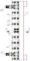
图1是本发明的结构示意图;Fig. 1 is the structural representation of the present invention;
图2是图1中B处的放大图;Fig. 2 is the enlarged view of B place in Fig. 1;
图3是使用状态下本发明的俯视结构示意图;Fig. 3 is the top view structure schematic diagram of the present invention under the use state;
图4是图2的B-B向视图;FIG. 4 is a view taken along the line BB of FIG. 2;
图5是图4中C处的放大图;Fig. 5 is the enlarged view at C place in Fig. 4;
图6是左驱动装置和右驱动装置的结构示意图;Fig. 6 is the structural representation of the left drive device and the right drive device;
图7是图3中A处的放大图;Fig. 7 is the enlarged view of A place in Fig. 3;
图8是图1的A-A向视图。FIG. 8 is a view taken along the line AA of FIG. 1 .
具体实施方式Detailed ways
如图1至图8所示,本发明提供了一种型钢弯曲加工方法,通过顶拉式型钢弯曲机进行;型钢8(工字钢或H型钢)包括相对设置的前端板10、后端板11和连接在前端板10和后端板11之间的中间板12;本发明的顶拉式型钢弯曲机包括型钢限位输送机构、型钢双向同步弯曲装置和弯曲度测量装置;As shown in FIGS. 1 to 8 , the present invention provides a method for bending a section steel, which is carried out by a top-pull section steel bending machine; the section steel 8 (I-beam or H-beam) includes a
型钢限位输送机构包括工作台1,工作台1的右端为型钢8的上料端2,工作台1的左端为型钢8的下料端3;The section steel limit conveying mechanism includes a
工作台1左端部设有用于驱动型钢8的左驱动装置31,工作台1右端部设有用于驱动型钢8的右驱动装置32;The left end of the
左驱动装置31和右驱动装置32之间的工作台1上左右间隔设有若干用于承托矫正型钢8的矫正限位装置33;A plurality of
工作台1左右方向的中部位置设有用于在垂直于型钢8长度方向上对型钢8施加弯曲力的所述型钢双向同步弯曲装置;型钢双向同步弯曲装置在左右方向上位于两个矫正限位装置33之间;The middle position of the
型钢双向同步弯曲装置包括固定连接在工作台1上的支撑架,支撑架顶部沿前后方向平行并排固定设有两道上导轨13,支撑架底部沿前后方向平行并排固定设有两道下导轨14;The profiled steel bidirectional synchronous bending device includes a support frame fixedly connected to the
支撑架中部前后相对设有顶轮箱15和拉轮箱16,顶轮箱15位于拉轮箱16正前方,顶轮箱15和拉轮箱16的顶部均与上导轨13滑动配合且二者的底部均与下导轨14滑动配合;The
顶轮箱15内转动连接有顶轮17,拉轮箱16内上下间隔转动连接有上拉轮18和下拉轮19,上拉轮18和下拉轮19之间的间隙与型钢8的中间板12厚度相适配;上拉轮18和下拉轮19均用于向后紧压型钢8的后端板11,顶轮17用于向后紧压型钢8的前端板10;The top pulley 17 is rotatably connected in the
支撑架后部通过拉缸安装座20安装有拉缸液压缸21,支撑架前部通过顶缸安装座22安装有顶缸液压缸23,拉缸液压缸21的伸出杆铰接有拉缸连接座24,拉缸连接座24与拉轮箱16固定连接;顶缸液压缸23的伸出杆铰接有顶缸连接座25,顶缸连接座25与顶轮箱15固定连接;顶轮17后端与拉轮后端之间的距离与型钢8宽度相适配。支撑架由所述拉缸安装座20、顶缸安装座22、两道上导轨13和两道下导轨14组成。The rear part of the support frame is installed with a pulling cylinder
弯曲度测量装置包括横梁4,横梁4铰接在型钢限位输送机构的工作台1的下料端3部;横梁4中部固定连接有弯曲度测量用位移传感器5,弯曲度测量用位移传感器5具有用于测量型钢8拱高的伸缩测量杆6,伸缩测量杆6的自由端与型钢8背离其圆心的一侧表面相接;弯曲度测量用位移传感器5两侧的横梁4上对称设有弦长杆7,弦长杆7的自由端与型钢8背离其圆心的一侧表面相接。The bending degree measuring device includes a
顶轮箱15内固定有竖向设置的顶轮轴26,顶轮轴26通过轴承连接所述顶轮17;拉轮箱16上部固定有竖向设置的上拉轮轴27,拉轮箱16下部固定有竖向设置的下拉轮轴28;上拉轮轴27通过轴承连接所述上拉轮18,下拉轮轴28通过轴承连接所述下拉轮19。The
所述横梁4与型钢限位输送机构的工作台1之间连接有拉簧9;所述弦长杆7的自由端和伸缩测量杆6的自由端均呈锥形,且尖端朝向型钢8。这样的结构,使得两根弦长杆7之间的长度更加精确,也使伸缩测量杆6的伸缩长度更加精准,提高型钢8弯曲度的测量精度。A tension spring 9 is connected between the
测量型钢8弯曲度时,两根弦长杆7长度固定,因此两根弦长杆7自由端之间的距离(即被测型钢段的弦长)固定。进而,伸缩测量杆6测量出的被测型钢段的拱高就仅由型钢8的弯曲度来决定,拱高与弯曲度之间具有一一对应的关系。通过伸缩测量杆6测量出的被测型钢段的拱高就可换算出型钢8的弯曲度。换算方法是常规技术,具体不再详述。When measuring the bending degree of the
左驱动装置31和右驱动装置32结构相同,均由上至下包括电动机35、与电动机35输出轴传动连接的摆线针轮减速器36、自下而上与摆线针轮减速器36的输出轴相连接的十字滑块联轴器37以及用于通过摩擦力驱动型钢8的主动轮39,主动轮39与被输送的型钢8的后端板11相压接;主动轮39的轴自下而上与十字滑块联轴器37相连接;主动轮39通过轴承安装于主动箱体38上,主动箱体38固定在工作台1上。The
矫正限位装置33包括中空的固定架40,每套矫正限位装置33的固定架40在被输送的型钢8前后两侧对称设有两套;The correcting and limiting
每套矫正限位装置33的两个固定架40下部通过轴承安装有用于承托型钢8的托辊41,每套矫正限位装置33的两个固定架40上部设有用于限定型钢8顶部位置的压辊42;The lower parts of the two fixing
压辊42通过轴承转动连接有滑动座43,托辊41通过轴承转动连接有固定座44,固定座44与固定架40固定连接;滑动座43向上固定连接有受力筒45,受力筒45内插设有调节丝杠46,调节丝杠46向上伸出固定架40且其顶部连接有水平设置的把手47。The
所述受力筒45中部设有螺纹孔,所述调节丝杠46与螺纹孔相应的部分设有环形凹槽48,受力筒45通过螺纹孔螺纹连接有定位螺栓49,定位螺栓49伸入所述环形凹槽48。环形凹槽48的设置,使得定位螺栓49不会妨碍调节丝杠46的旋转,同时又使调节丝杠46、定位螺栓49和受力筒45在上下方向上形成联动关系,使得调节丝杠46的上下运动可以通过受力筒45和滑动座43转化为压辊42的上下运动。如果没有定位螺栓49和受力筒45以及环形凹槽48,则调节丝杠46只能对压辊42施加向下的压力,不能将压辊42向上提起来。A threaded hole is provided in the middle of the
电控装置可以采用51单片机、52单片机以及PLC等,为常规技术,图未示。The electronic control device can use 51 single-chip microcomputer, 52 single-chip microcomputer and PLC, etc., which are conventional technologies, and are not shown in the figure.
本发明的型钢弯曲加工方法按以下步骤进行:The section steel bending processing method of the present invention is carried out according to the following steps:
第一步骤是准备步骤;The first step is the preparation step;
先通过旋转把手47,确保各压辊42与托辊41之间的距离大于型钢8的前端板10和后端板11的高度;First, by rotating the
第二步骤是初始上料步骤;将型钢8由左至右依次穿过各矫正限位装置33以及所述型钢双向同步弯曲装置,使各矫正限位装置33处的型钢8由各矫正限位装置33的压辊42和托辊41之间穿过,并使型钢双向同步弯曲装置处的型钢8由上拉轮18和下拉轮19之间的间隙处穿过;使型钢8的前端板10向前与顶轮17后端相接,使型钢8的后端板11向前与上拉轮18和下拉轮19的后端相接。The second step is the initial feeding step; the
然后,调节旋转把手47,使压辊42向下与型钢8相接触;既实现压辊42和托辊41在上下方向上对型钢8进行限位,又不使压辊42与型钢8之间的摩擦力过大,从而降低型钢8输送过程中的能耗。Then, adjust the
第三步骤是弯曲加工步骤;The third step is a bending step;
使拉缸液压缸21和顶缸液压缸23同步动作,拉缸液压缸21的伸出杆通过拉缸连接座24、拉轮箱16、上拉轮轴27和下拉轮轴28带动上拉轮18和下拉轮19向后拉动型钢8的后端板11,顶缸液压缸23的伸出杆通过顶缸连接座25、顶轮箱15、顶轮轴26和顶轮17向后顶压型钢8的前端板10,型钢8由于其前端板10和后端板11同步受力而发生弯曲;The pulling cylinder
由于型钢8在弯曲过程中,前部和后部同时受力,因而型钢8各部分受力更为均匀,与以往相比大幅降低了弯曲过程中发生不可控变形的概率。Since the front part and the rear part of the
同步启动左驱动装置31和右驱动装置32的电动机35,电动机35通过摆线针轮减速器36、十字滑块联轴器37驱动主动轮39旋转,主动轮39通过摩擦力驱动型钢8向左移动,移动中的型钢8在通过型钢双向同步弯曲装置时由于其前端板10和后端板11同步受力而发生弯曲;The
弯曲后的型钢8向左送出工作台1。The
在第三步骤中还包括有弯曲度调整操作;弯曲度调整操作是:The third step also includes a curvature adjustment operation; the curvature adjustment operation is:
型钢8在向左离开工作台1时,拉簧9能够通过自身的弹力自动拉动横梁4,使弦长杆7和伸缩测量杆6均紧压在型钢8上;这样就解放了工作人员,工作中工作人员无须另外采取措施保证弦长杆7和伸缩测量杆6均紧压在型钢8上。When the
准确地说,型钢8被弯曲后,每段弯曲的型钢8均为弧线,具有圆心,弦长杆7和伸缩测量杆6均紧压在型钢8背离其圆心的一侧表面。To be precise, after the
弦长杆7和伸缩测量杆6均紧压在型钢8上,这样才能保证伸缩测量杆6测量的拱高是准确的拱高值。Both the chord length rod 7 and the
加工同一批次的型钢8具有统一的目标弯曲度,目标弯曲度对应有预定拱高,即型钢8弯曲至目标弯曲度后,弯曲度测量用位移传感器5测量出的拱高是固定的,为预定拱高。加工过程中,通过弯曲度测量装置测量加工后型钢8的实测拱高;The profiled
如果实测拱高低于预定拱高,说明型钢8的弯曲程度低于目标弯曲度,此时对型钢双向同步弯曲装置进行调整,加大顶缸液压缸23的伸出杆和拉缸液压缸21的伸出杆的伸出量,从而增大型钢8的弯曲程度;If the measured arch height is lower than the predetermined arch height, it means that the bending degree of the
如果实测拱高高于预定拱高,说明型钢8的弯曲程度高于目标弯曲度,此时对型钢双向同步弯曲装置进行调整,减少顶缸液压缸23的伸出杆和拉缸液压缸21的伸出杆的伸出量,从而减小型钢8的弯曲程度;If the measured arch height is higher than the predetermined arch height, it means that the bending degree of the
通过弯曲度调整操作将型钢8的弯曲度控制在目标弯曲度范围及预定的公差范围内。The curvature of the shaped
如果实测拱高等于预定拱高,则表明型钢8的弯曲程度刚好,不需要调整顶拉式型钢弯曲机的工作状态。If the measured arch height is equal to the predetermined arch height, it indicates that the bending degree of the
顶拉式型钢弯曲机还包括有电控装置,弯曲度测量用位移传感器5、拉缸液压缸21和顶缸液压缸23分别连接电控装置;拉缸安装座20上设有用于测量拉缸液压缸21的伸出杆位移量的拉缸位移传感器29,顶缸安装座22上设有用于测量顶缸液压缸23的伸出杆位移量的顶缸位移传感器30,顶缸位移传感器30和拉缸位移传感器29分别连接电控装置;The top-pull type steel bending machine also includes an electric control device. The
在进行弯曲度调整操作时,电控装置接收弯曲度测量用位移传感器5的信号,相应调整顶缸液压缸23的伸出杆和拉缸液压缸21的伸出杆的伸出量;电控装置通过接收拉缸位移传感器29和顶缸位移传感器30的信号,对顶缸液压缸23的伸出杆和拉缸液压缸21的伸出杆的伸出量进行精确调整。通过拉缸位移传感器29和顶缸位移传感器30可以精确监控拉缸液压缸21和顶缸液压缸23的动作,从而使拉缸液压缸21和顶缸液压缸23的动作幅度与预定值(取决于预定的型钢弯曲程度)相同。During the bending adjustment operation, the electronic control device receives the signal of the
当然,顶缸液压缸23的伸出杆和拉缸液压缸21的伸出杆的伸出量也可以由工作人员根据弯曲度测量装置的测量结果进行人工控制和调整。Of course, the extension amount of the extension rod of the top cylinder
以上实施例仅用以说明而非限制本发明的技术方案,尽管参照上述实施例对本发明进行了详细说明,本领域的普通技术人员应当理解:依然可以对本发明进行修改或者等同替换,而不脱离本发明的精神和范围的任何修改或局部替换,其均应涵盖在本发明的权利要求范围当中。The above embodiments are only used to illustrate rather than limit the technical solutions of the present invention. Although the present invention has been described in detail with reference to the above embodiments, those of ordinary skill in the art should understand that the present invention can still be modified or equivalently replaced without departing from the Any modification or partial replacement of the spirit and scope of the present invention should be included in the scope of the claims of the present invention.
Claims (3)
Priority Applications (1)
| Application Number | Priority Date | Filing Date | Title |
|---|---|---|---|
| CN201811388818.XA CN109500168B (en) | 2018-11-21 | 2018-11-21 | Section steel bending processing method |
Applications Claiming Priority (1)
| Application Number | Priority Date | Filing Date | Title |
|---|---|---|---|
| CN201811388818.XA CN109500168B (en) | 2018-11-21 | 2018-11-21 | Section steel bending processing method |
Publications (2)
| Publication Number | Publication Date |
|---|---|
| CN109500168A CN109500168A (en) | 2019-03-22 |
| CN109500168B true CN109500168B (en) | 2020-07-31 |
Family
ID=65749379
Family Applications (1)
| Application Number | Title | Priority Date | Filing Date |
|---|---|---|---|
| CN201811388818.XA Active CN109500168B (en) | 2018-11-21 | 2018-11-21 | Section steel bending processing method |
Country Status (1)
| Country | Link |
|---|---|
| CN (1) | CN109500168B (en) |
Families Citing this family (3)
| Publication number | Priority date | Publication date | Assignee | Title |
|---|---|---|---|---|
| CN112570514B (en) * | 2019-09-30 | 2022-11-11 | 比亚迪股份有限公司 | Section bar top bending machine and section bar top bending forming method |
| CN113579023B (en) * | 2021-06-23 | 2023-03-10 | 新乡市中智重工机械设备有限公司 | Section steel bending method based on laser measurement |
| CN113607089B (en) * | 2021-06-23 | 2023-11-10 | 新乡市中智重工机械设备有限公司 | Profile steel bending method based on visual measurement |
Family Cites Families (5)
| Publication number | Priority date | Publication date | Assignee | Title |
|---|---|---|---|---|
| CN87205433U (en) * | 1987-11-27 | 1988-10-05 | 华北石油管理局第一油田建设公司 | Combined apparatus for push bending steel shapes through intermediate-frequency heating |
| CN2491146Y (en) * | 2001-07-12 | 2002-05-15 | 余波 | Push-pull roller type cold bender |
| CN1156671C (en) * | 2002-04-19 | 2004-07-07 | 吉林大学 | Curved surface measurer |
| CN100478095C (en) * | 2005-12-30 | 2009-04-15 | 上海船舶工艺研究所 | Machining apparatus for digital control rib cold bending machining and products produced thereby |
| CN203853419U (en) * | 2014-05-16 | 2014-10-01 | 四川工程职业技术学院 | Section steel bending machine |
-
2018
- 2018-11-21 CN CN201811388818.XA patent/CN109500168B/en active Active
Also Published As
| Publication number | Publication date |
|---|---|
| CN109500168A (en) | 2019-03-22 |
Similar Documents
| Publication | Publication Date | Title |
|---|---|---|
| CN212285382U (en) | A steel plate straightening machine | |
| CN208116438U (en) | It is a kind of for aligning the straightener and its feed device of camber | |
| CN113547005B (en) | Positive and negative bending equipment of section bar of variable camber | |
| CN104525766B (en) | A kind of plate feeding device | |
| CN109226351B (en) | A fully automatic H-beam horizontal straightening machine | |
| CN109317539A (en) | A straightening method and straightening device and guide rail straightening machine using the same | |
| CN219296767U (en) | guide wheel | |
| CN109127782B (en) | Straightening machine | |
| CN114345987A (en) | Steel plate flattening device | |
| CN217017978U (en) | Guiding mechanism for outlet plate blank of finishing mill | |
| CN109500168A (en) | Fashioned iron bend processing method | |
| CN205110414U (en) | U shaped steel forming production line equipment | |
| CN209020981U (en) | A kind of horizontal straightening machine of full-automatic H profile steel | |
| CN209035206U (en) | Push-pull-type formed steel bending machine | |
| CN109290408B (en) | Top-pull type steel bending machine | |
| CN115475892A (en) | Flat steel straightening and feeding machine | |
| CN115255033A (en) | Servo-driven plate leveling device and leveling control method | |
| CN206810893U (en) | A compact combined straightening equipment of a turning machine and a flattening machine | |
| CN110756626B (en) | A multi-specification special-shaped channel steel adaptive 3D cold bending forming device | |
| CN212944721U (en) | Straightening device for aluminum-plastic composite board production | |
| CN221500044U (en) | Feeder for steel belt discharging device | |
| CN222058521U (en) | A boiler container metal plate leveling device | |
| CN218283303U (en) | Metal thin-wall plate edge folding and bending forming equipment capable of automatically adjusting roller shaft | |
| CN209035205U (en) | I-steel bi-directional synchronization bending apparatus | |
| CN220739007U (en) | Belted steel orthotic devices suitable for hot tandem rolling coiler |
Legal Events
| Date | Code | Title | Description |
|---|---|---|---|
| PB01 | Publication | ||
| PB01 | Publication | ||
| SE01 | Entry into force of request for substantive examination | ||
| SE01 | Entry into force of request for substantive examination | ||
| GR01 | Patent grant | ||
| GR01 | Patent grant | ||
| TR01 | Transfer of patent right | ||
| TR01 | Transfer of patent right |
Effective date of registration: 20210629 Address after: 453000 No.16, sizhuangding Industrial Park, Muye District, Xinxiang City, Henan Province Patentee after: Xinxiang Zhongzhi Heavy Industry Machinery Equipment Co.,Ltd. Address before: 450018 room 710, 7th floor, building 3, Xiangsheng street, Zhengdong New District, Zhengzhou City, Henan Province Patentee before: HENAN ZHONGZHI HEAVY MACHINERY EQUIPMENT Co.,Ltd. |