Method and device for drying granular materials
Technical Field
The invention belongs to the technical field of drying, and particularly relates to a method and a device for drying granular materials in a vertical static device.
Background
The rotary drum dryer is a large-scale horizontal drying mobile device, transfers and dries materials by using a drum rotation and air convection mode, has large handling capacity, but has lower thermal efficiency when the temperature of hot air is not high. Therefore, various types of improved structures have been developed, in which a steam pipe rotary drum dryer indirectly heated by steam has been used, and the thermal efficiency is greatly improved.
The steam pipe rotary drum dryer is a large-scale energy-saving drying device, has the advantages of obvious reliable operation, energy conservation and the like in the industry needing to treat materials in large scale, can be widely applied to drying various non-viscous powder granular materials, and obtains materials for popularization and application such as drying of PTA, TA, HDPE, lignite, coking coal, white carbon black, calcium carbonate, copper concentrate, lead concentrate, sulfur concentrate and the like, and calcining of gypsum, heavy alkali and the like.
Although steam pipe rotary drum dryers have their distinct advantages, they still suffer from the following disadvantages: 1. the device is horizontally placed, and the occupied area is large. 2. Low filling rate and large equipment investment. 3. The cylinder body needs to be driven by a motor to rotate, and power consumption is high.
Disclosure of Invention
In order to solve the above-mentioned drawbacks of the prior art, the present invention provides a method and an apparatus for drying particulate materials, which solves the problems of the prior art.
The invention is realized by the following technical scheme.
A method of drying particulate material comprising the steps of:
1) the particle materials enter from a feeding pipe at the upper part of the drying device, are indirectly heated by a heat medium in a heat exchanger in the drying device, the temperature of the materials is raised to 80-150 ℃, moisture evaporated from the particle materials is taken away by carrier gas, and the dried materials are discharged from a pipe joint at the lower part of the drying device;
2) carrier gas entering the carrier gas distributor through the carrier gas guide pipe is uniformly distributed into the material layer through the carrier gas angle pipe, and water evaporated by the carrier gas carrying the particle material passes through gaps among the materials, is collected by a tail gas collector formed by the tail gas angle pipe and then is discharged through the tail gas guide pipe;
3) and the carrier gas is dedusted in the deduster through the tail gas outlet pipe, then is conveyed to the cooler through the induced draft fan, and the cooled tail gas in the cooler is discharged after reaching the standard.
Preferably, the carrier gas is introduced into the carrier gas distributor from the carrier gas inlet pipe to the carrier gas conduit by the blower.
The invention also provides a device for drying the granular materials, which comprises a bin body, wherein the bin body is formed by connecting a bin body, a conical joint and a pipe joint; the bin body is sequentially provided with a tail gas collector, a heat exchanger and a carrier gas distributor from top to bottom; wherein, the tail gas collector, the heat exchanger and the carrier gas distributor are respectively fixedly connected with the bin body; the tail gas collector, the heat exchanger and the carrier gas distributor form a drying unit.
Preferably, 1 or more drying units can be arranged in the bin body.
Preferably, the top of the bin body is provided with a cover plate, and the feeding pipe is arranged on the cover plate.
Preferably, the tail gas collector is formed by connecting a plurality of tail gas transverse angle pipes and tail gas longitudinal angle pipes in a staggered manner, and the tail gas longitudinal angle pipes are communicated with the tail gas transverse angle pipes; the tail gas guide pipe is communicated with the tail gas transverse corner pipe and led out from the side wall of the bin body.
Preferably, the heat exchanger is of a rectangular frame structure formed by connecting a plurality of transverse pipes and a plurality of longitudinal pipes in a staggered manner, a plurality of vertical pipes are vertically welded along the rectangular frame to form a three-dimensional frame pipe, and the vertical pipes are distributed on the intersection points of the transverse pipes and the longitudinal pipes and the middle parts of adjacent intersection points; the horizontal pipe, the longitudinal pipe and the vertical pipe are communicated with each other; the top horizontal pipe is provided with an outlet, the bottom horizontal pipe is provided with an inlet, and the inlets are respectively led out from the side wall of the bin body.
Preferably, the carrier gas distributor is formed by connecting a plurality of carrier gas transverse angle pipes and carrier gas longitudinal angle pipes in a staggered manner, and the carrier gas transverse angle pipes are communicated with the carrier gas longitudinal angle pipes; the carrier gas conduit is communicated with the carrier gas transverse angle pipe and is led out from the side wall of the bin body.
Preferably, the bin body of the bin body is rectangular, circular, semicircular, oval, prismatic or polygonal with mutually unequal side lengths.
Compared with a rotary drum dryer, the device has the following beneficial effects under the conditions of treating the same material, the same treatment capacity and achieving the same drying effect:
1. granular materials are filled in the bin body, so that the contact area between the materials and the heat exchanger is large, and the filling rate is high; namely, the effective heating area is large, and the required total heat exchange area is small; and the required equipment has small volume and small device specification.
2. The device adopts a vertical static device, the materials fall in the device by the self gravity, the power consumption is low, and the investment cost is low.
Drawings
The accompanying drawings, which are included to provide a further understanding of the invention and are incorporated in and constitute a part of this application, illustrate embodiment(s) of the invention and together with the description serve to explain the principles of the invention:
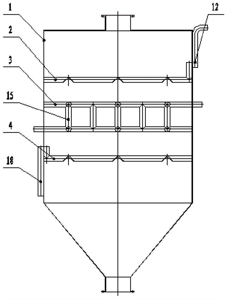
FIG. 1 is a schematic view of a drying apparatus according to the present invention;
FIG. 2 is a schematic view of the cartridge body structure;
FIG. 3 is a schematic view of an exhaust collector;
FIG. 4 is a schematic diagram of a heat exchanger;
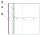
FIG. 5 is a schematic view of a carrier gas distributor;
FIG. 6 is a flow chart of the process of the present invention.
In the figure: 1. the device comprises a bin body, 2, a tail gas collector, 3, a heat exchanger, 4, a carrier gas distributor, 5, a feeding pipe, 6, a cover plate, 7, a bin body, 8, a conical joint, 9, a pipe joint, 10, a tail gas longitudinal angle pipe, 11, a tail gas transverse angle pipe, 12, a tail gas guide pipe, 13, a transverse pipe, 14, a longitudinal pipe, 15, a vertical pipe, 16, a carrier gas longitudinal angle pipe, 17, a carrier gas transverse angle pipe, 18, a carrier gas guide pipe, 19, a drying device, 20, an air blower, 21, a dust remover, 22, an induced draft fan, 23, a cooler, 24, a carrier gas inlet pipe, 25, a tail gas outlet pipe, 26, a heat medium inlet pipe, 27 and a heat medium outlet pipe.
Detailed Description
The present invention will now be described in detail with reference to the drawings and specific embodiments, wherein the exemplary embodiments and descriptions of the present invention are provided to explain the present invention without limiting the invention thereto.
As shown in fig. 1 and 2, the device for drying granular materials of the invention comprises a bin body 1, wherein the bin body 1 is formed by connecting a bin body 7, a conical joint 8 and a pipe joint 9; the top of the bin body 7 is provided with a cover plate 6, and the feeding pipe 5 is arranged on the cover plate 6. The bin body 7 is sequentially provided with a tail gas collector 2, a heat exchanger 3 and a carrier gas distributor 4 from top to bottom. Wherein, the tail gas collector 2, the heat exchanger 3 and the carrier gas distributor 4 are respectively fixedly connected with the bin body 7. The tail gas collector 2, the heat exchanger 3 and the carrier gas distributor 4 form a drying unit. Within the housing 7, 1 or more drying units may be arranged. The bin body 7 of the device can be rectangular, circular, semicircular, oval, prismatic or polygonal with mutually unequal side lengths.
As shown in fig. 3, the exhaust gas collector 2 is formed by connecting a plurality of exhaust gas transverse angle pipes 11 and exhaust gas longitudinal angle pipes 10 in a staggered manner, and the exhaust gas longitudinal angle pipes 10 are communicated with the exhaust gas transverse angle pipes 11. The tail gas guide pipe 12 is communicated with the tail gas transverse corner pipe 11 and is led out from the side wall of the bin body 7.
As shown in fig. 4, the heat exchanger 3 is formed by connecting a plurality of transverse pipes 13 and a plurality of longitudinal pipes 14 in a staggered manner to form a rectangular frame structure, a plurality of vertical pipes 15 are vertically welded along the rectangular frame to form a three-dimensional frame pipe, and the vertical pipes 15 are distributed on the intersection points of the transverse pipes 13 and the longitudinal pipes 14 and in the middle of the adjacent intersection points. The cross pipe 13, the longitudinal pipe 14 and the stand pipe 15 are communicated with each other. The top horizontal pipe 13 is provided with a heat exchange medium inlet, and the bottom horizontal pipe 13 is provided with a heat exchange medium outlet which are respectively led out along the side wall of the bin body 7.
As shown in fig. 5, similar to the structure of the exhaust collector 2, the carrier gas distributor 4 is provided with a carrier gas transverse angular pipe 16 and a carrier gas longitudinal angular pipe 16, a plurality of carrier gas transverse angular pipes 17 are connected with the carrier gas longitudinal angular pipe 16 in a staggered manner, and the carrier gas transverse angular pipes 17 are communicated with the carrier gas longitudinal angular pipe 16. The carrier gas conduit 18 is communicated with the carrier gas transverse angle pipe 17 and led out from the side wall of the bin body 7.
As shown in fig. 6, the working process of the device of the present invention is as follows:
the granular material enters the drying device through the feeding pipe 5 at the upper part of the drying device 19, is indirectly heated by the heat medium in the heat exchanger 3 in the drying device, the temperature of the material is raised to 80-150 ℃, moisture evaporated from the granular material is taken away by carrier gas, and the dried material is discharged from the lower pipe joint 9 of the drying device. Carrier gas enters the carrier gas distributor 4 from a carrier gas inlet pipe 24 to a carrier gas guide pipe 18 by an air blower 20, the carrier gas is uniformly distributed in the carrier gas longitudinal angle pipe 16 and the carrier gas transverse angle pipe 17 to enter the material layer, the carrier gas uniformly passes through gaps among the particle materials, the carrier gas carries evaporated moisture to pass through the gaps among the materials, and the moisture is collected by a tail gas collector 2 consisting of a tail gas longitudinal angle pipe 10 and a tail gas transverse angle pipe 11 and then is discharged out of the drying device by a tail gas guide pipe 12; and the tail gas is introduced into a dust remover 21 through a tail gas outlet pipe 25 for dust removal, then is conveyed to a cooler 23 through a draught fan 22, and is cooled in the cooler 23 and discharged after reaching the standard.
Examples
The invention is further illustrated by the following 3 drying examples.
Taking drying lignite as an example, the analogy of the present invention to a steam pipe rotary drum dryer is listed below:
| |
steam pipe rotary drum dryer
|
The drying device
|
| Drying the material
|
Brown coal
|
Brown coal
|
| Particle size of material mm
|
6~30
|
6~30
|
| Feed rate, t/h
|
53
|
53
|
| Feed water content%
|
21%
|
21%
|
| Discharge water content%
|
5%
|
5%
|
| Steam consumption, t/h
|
14
|
14
|
| Device specification, m
|
Phi 3.5m × 28m (outer diameter × length)
|
3.1m 13m (base X height)
|
| Filling rate%
|
20%
|
43%
|
| Power consumption, kW
|
185
|
12
|
| Coefficient of equipment investment
|
100
|
40 |
Under the conditions of treating the same material, treating the same treatment amount and achieving the same drying effect, the device has the advantages of small heat exchange area, small device specification, high filling rate, low power consumption and low investment cost.
The present invention is not limited to the above-mentioned embodiments, and based on the technical solutions disclosed in the present invention, those skilled in the art can make some substitutions and modifications to some technical features without creative efforts according to the disclosed technical contents, and these substitutions and modifications are all within the protection scope of the present invention.