Medical waste classification collecting box
Technical Field
The invention relates to the technical field of medical treatment and health, in particular to a medical waste classification and collection box.
Background
The medical garbage refers to the polluted garbage produced by hospitals, such as used cotton balls, sandcloths, disposable medical appliances, postoperative wastes, overdue medicines and the like, because the medical garbage has the characteristics of space pollution, acute infection, latent pollution and the like, serious environmental pollution can be caused by improper treatment, and the polluted garbage can also become a source of epidemic diseases, so that the medical garbage is collected and classified by a special collecting box in the market, the possible environmental pollution caused by the medical garbage is reduced, but the existing medical garbage classifying and collecting box has a single function, in the process of delivering the garbage, non-sterile gas in the collecting box easily overflows from a throwing port to cause peripheral environmental pollution, the influence on the body health of personnel throwing in the garbage and recovering the garbage is caused, meanwhile, no disinfection measures are arranged near the collecting box, and after a plastic bag loaded with the medical garbage is crushed, the medical waste is easy to scatter, so that germs are diffused to form medical accidents.
Disclosure of Invention
The invention provides a medical waste classifying and collecting box, which can effectively solve the problems that the existing medical waste classifying and collecting box in the background technology has single function, unsterilized gas in the collecting box easily overflows from a throwing opening in the process of delivering waste to cause pollution to the surrounding environment and influence on the body health of people throwing the waste and recovering the waste, meanwhile, no disinfection measures are arranged near the collecting box, and medical waste is easy to scatter after a plastic bag loading the medical waste is broken, so that germs are easy to diffuse, and medical accidents are caused.
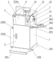
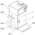
In order to achieve the purpose, the invention provides the following technical scheme: a medical waste classification collecting box comprises a box body, wherein a box door is hinged to the middle of the front end face of the box body, a throwing port is formed in the top of the front end face of the box body, a rain-proof cover is welded to the top of the box body, a centrifugal fan is installed in the middle of the surface of one side of the rain-proof cover, the input end of the centrifugal fan is electrically connected with the output end of a power supply, an exhaust box is embedded and installed at the top end of the rain-proof cover corresponding to the top end of the throwing port, an exhaust hopper is welded to the bottom end of the exhaust box, an exhaust branch pipe is installed at one end of the exhaust box, a choke plate is rotatably connected to the position of one side, corresponding to the exhaust branch pipe, of the exhaust box, a traction rope is installed at one end of the choke plate, a buckle is installed at one end of, the rain-proof cover is characterized in that one end of the elastic rope is fixedly connected with one end of the wind-blocking plate, the position, corresponding to the exhaust branch pipe, of the top end of the rain-proof cover is welded with the liquid storage box, the middle of the liquid storage box is rotatably connected with the stand column, power fan blades are installed at the bottom of the stand column, the top end of the stand column is welded with the top plate, and the bottom end of the top plate.
Preferably, the limit blocks are symmetrically welded at the positions, corresponding to the two sides of the traction rope, of the edge of the top end of the rain cover.
Preferably, one end of the air exhaust box is fixedly connected with the top end of the centrifugal fan through a vent pipe.
Preferably, the exhaust branch pipe is shaped like a Chinese character ji.
Preferably, the box body is provided with a block-up assembly at the bottom, and the block-up assembly comprises a base plate, a receiving chamber, a limiting fixture block, an adjusting spring, a block-up plate, a gasket, a clamping groove, a notch, a sliding clamping column, an adjusting plate, a first clamping plate, a second clamping plate and a reset spring;
the welding of bottom half has the bed plate, the inside storage cavity that has seted up of bed plate, it has spacing fixture block to accomodate cavity bottom symmetrical welding, accomodate the inside terminal surface of cavity and install adjusting spring, the bed hedgehopping board is installed to adjusting spring one end, a bed hedgehopping board terminal surface bonds has the gasket, the draw-in groove has all been seted up on bed hedgehopping board both sides surface, accomodate the inside bilateral symmetry of cavity and seted up the notch, the inside sliding connection of notch has the slip card post, slip card post top is connected with the regulating plate through the rotation of monaural ring installed part, slip card post both sides surface middle part has all welded first cardboard, slip card post both sides surface tip has all welded the second cardboard, reset spring is installed to a second cardboard terminal surface, reset spring one end and notch inner wall fixed connection.
Preferably, the outer surface of the cross section of the raised plate is matched with the inner edge of the cross section of the receiving cavity.
Preferably, the number of the adjusting springs is three.
Preferably, a disinfection component is mounted on one end face of the middle of the box body, and the disinfection component comprises a fixed lug plate, a mounting plate, an ultraviolet disinfection lamp, a disinfection wet tissue storage box, a fixed threaded sleeve, a butterfly bolt and a cover plate;
the utility model discloses a disinfection box, including box, mounting panel, ultraviolet disinfection lamp, mounting panel bottom mid-mounting, mounting panel bottom end electric connection, the input of ultraviolet disinfection lamp and the output electric connection of power, the welding of mounting panel top has the wet piece of cloth receiver of disinfection, the welding of the inside top of the wet piece of cloth receiver of disinfection has fixed swivel nut, fixed swivel nut top is connected with butterfly bolt through the thread engagement, the apron is installed through sealed bearing in the butterfly bolt top.
Preferably, the box middle part one end face corresponds fixed otic placode both sides position department and all has welded the backup pad, the horizontal height in backup pad top is the same with the horizontal height of mounting panel bottom.
Preferably, a liquid storage assembly is mounted on one side of the box body and comprises a liquid storage box, observation glass, a screw, a drainage plate, a screw hole, a crank, a drainage pipe and a water inlet;
the utility model discloses a box, including box, water storage tank, screw rod, crank, water storage tank, water storage box bottom, drain pipe, the welding of box one side has the liquid storage tank, observation glass is installed in the embedding of liquid storage tank terminal surface limit portion, the screw rod is installed on the liquid storage tank top, the screw rod mid-mounting has the drain bar, the screw has been seted up at the drain bar middle part, the screw rod passes through the thread engagement with the screw and is connected, the crank is installed on the screw rod top, the water inlet is installed to a liquid storage tank top tip, the.
Compared with the prior art, the invention has the beneficial effects that: the invention has scientific and reasonable structure and safe and convenient use:
1. the exhaust box and the exhaust funnel are arranged, air flow generated by the centrifugal fan passes through the exhaust funnel, the vent pipe enters the exhaust box, and the vent pipe is sprayed out through the exhaust funnel to form an air wall, so that the condition that harmful gas in the box body overflows in the process of putting medical waste is effectively avoided, and the harmful gas is prevented from overflowing through a throwing opening to cause environmental pollution.
2. The gas through exhaust branch promotes power flabellum, discharges after the antiseptic solution in holding the liquid box is moist, effectively disinfects all ring edge borders, guarantees the clean air near medical waste collection box, and the gas of exhaust branch combustion gas promotes power flabellum simultaneously, drives stand, roof and dispersion flabellum and rotates for gas after the moist can be irregular to peripheral diffusion, improves the disinfection effect.
3. Through pulling choke plate, the effect of cooperation elasticity rope can effectively be adjusted the air output of hopper and exhaust branch to can choose to plug up one of them, play the effect of single use, the effectual switching of two kinds of functions of being convenient for is used.
4. Through taking out and accomodating the bed hedgehopping board, the user of the different heights of being convenient for drops into rubbish and throws in the mouth, avoids leading to rubbish to put in the person because of the height and uses inconveniently, has set up slip card post and regulating plate simultaneously, through stepping on the regulating plate both ends, realizes the slip block of slip card post, can be convenient will slide the card post and take out from the draw-in groove, make things convenient for taking out and accomodating of bed hedgehopping board.
5. Set up the disinfection subassembly, when medical waste is touched by accident to the relevant personnel, through the inside wet piece of cloth of placing of ultraviolet ray disinfection lamp and the wet piece of cloth receiver of disinfection, can effectually disinfect, avoid the germ to the infringement of human body and the emergence of medical accident, set up fixed swivel nut simultaneously, apron and butterfly bolt, reduce the wet piece of cloth and the outside air contact of the inside wet piece of cloth of placing of the wet piece of cloth receiver of disinfection, improve the life of the wet piece of cloth of disinfection, guarantee the result of use that disinfects and use.
6. The liquid storage assembly is arranged, the crank is rotated to drive the screw to rotate, the screw is meshed with the screw hole in a matched mode, the extruding plate extrudes downwards, disinfectant is extruded into the liquid storage box through the drain pipe, disinfectant in the liquid storage box is effectively supplemented, the observation glass is arranged, disinfectant content in the liquid storage box can be observed conveniently, and then disinfectant can be added through the water inlet in time.
Drawings
The accompanying drawings, which are included to provide a further understanding of the invention and are incorporated in and constitute a part of this specification, illustrate embodiments of the invention and together with the description serve to explain the principles of the invention and not to limit the invention.
In the drawings:
FIG. 1 is a schematic structural view of the present invention;
FIG. 2 is a schematic structural view of the present invention;
FIG. 3 is a schematic view of the mounting structure of the buckle of the present invention;
FIG. 4 is a schematic view of the installation structure of the elastic cord of the present invention;
FIG. 5 is a schematic view of the mounting structure of the power fan blade of the present invention;
FIG. 6 is a schematic view of the installation structure of the drain board according to the present invention;
FIG. 7 is a schematic view of the construction of the sterilization assembly of the present invention;
FIG. 8 is a schematic view of the construction of the mat height assembly of the present invention;
FIG. 9 is a schematic structural view of region A of FIG. 8 according to the present invention;
reference numbers in the figures: 1. a box body; 2. a box door; 3. throwing in the mouth; 4. a rain cover; 5. a step-up assembly; 501. a base plate; 502. a receiving chamber; 503. a limiting clamping block; 504. adjusting the spring; 505. a step-up plate; 506. a gasket; 507. a card slot; 508. a notch; 509. sliding the clamping column; 510. an adjusting plate; 511. a first clamping plate; 512. a second clamping plate; 513. a return spring;
6. a sterilizing assembly; 601. fixing the ear plate; 602. mounting a plate; 603. an ultraviolet disinfection lamp; 604. a sterilized wet tissue storage box; 605. fixing the threaded sleeve; 606. a butterfly bolt; 607. a cover plate;
7. a centrifugal fan; 8. a venting box; 9. an exhaust funnel; 10. a breather pipe; 11. an exhaust branch pipe; 12. a choke plate; 13. a hauling rope; 14. a retaining ring; 15. fixing a column; 16. a fixed block; 17. an elastic cord; 18. a limiting block; 19. a reservoir cartridge; 20. a column; 21. a power fan blade; 22. a top plate; 23. dispersing fan blades;
24. a liquid storage assembly; 2401. a liquid storage tank; 2402. observing glass; 2403. a screw; 2404. a drain plate; 2405. a screw hole; 2406. a crank; 2407. a drain pipe; 2408. a water inlet; 25. and a support plate.
Detailed Description
The preferred embodiments of the present invention will be described in conjunction with the accompanying drawings, and it will be understood that they are described herein for the purpose of illustration and explanation and not limitation.
Example (b): as shown in figures 1-9, the invention provides a technical scheme, a medical waste classifying and collecting box comprises a box body 1, a box door 2 is hinged in the middle of the front end face of the box body 1, a throwing port 3 is arranged at the top of the front end face of the box body 1, a rain cover 4 is welded at the top of the box body 1, a centrifugal fan 7 is arranged in the middle of the surface of one side of the rain cover 4, the model of the centrifugal fan 7 is 150FLJ15/17, the input end of the centrifugal fan 7 is electrically connected with the output end of a power supply, an exhaust box 8 is embedded and installed at the position, corresponding to the top end of the throwing port 3, of the top end of the rain cover 4, in order to introduce air flow generated by the centrifugal fan 7 into an exhaust box 8, one end of the exhaust box 8 is fixedly connected with the top end of the centrifugal fan 7 through an air pipe 10, an exhaust funnel 9 is welded at the bottom end, a traction rope 13 is arranged at one end of the wind-proof plate 12, in order to avoid the stability of the traction rope 13 in the pulling process and reduce the shaking of the traction rope 13, limiting blocks 18 are symmetrically welded at the positions, corresponding to the two sides of the traction rope 13, of the edge part of the top end of the rain-proof cover 4, a retaining ring 14 is arranged at one end of the traction rope 13, a fixing column 15 is welded at the middle part of the side surface of the rain-proof cover 4, a fixing block 16 is arranged on the side surface, opposite to the wind-proof plate 12, of the inside of the wind exhaust box 8, an elastic rope 17 is arranged at one end of the fixing block 16, one end of the, in order to avoid the backflow of disinfectant in the liquid storage box 19, the exhaust branch pipe 11 is shaped like a Chinese character ji, the middle part of the liquid storage box 19 is rotatably connected with an upright post 20, the bottom of the upright post 20 is provided with power fan blades 21, the top end of the upright post 20 is welded with a top plate 22, and the bottom end of the top plate 22 is welded with dispersing fan blades 23 at equal intervals.
The bottom of the box body 1 is provided with a padding assembly 5, and the padding assembly 5 comprises a base plate 501, a receiving chamber 502, a limiting fixture block 503, an adjusting spring 504, a padding plate 505, a gasket 506, a clamping groove 507, a notch 508, a sliding clamping column 509, an adjusting plate 510, a first clamping plate 511, a second clamping plate 512 and a return spring 513;
the bottom of the box body 1 is welded with a base plate 501, a receiving chamber 502 is arranged in the base plate 501, limiting clamping blocks 503 are symmetrically welded at the bottom end of the receiving chamber 502, an adjusting spring 504 is arranged on one end face in the receiving chamber 502, a heightening plate 505 is arranged at one end of the adjusting spring 504, in order to ensure that the limiting clamping blocks 503 can effectively clamp the heightening plate 505 and ensure that the heightening plate 505 cannot fall off when moving, the outer surface of the cross section of the heightening plate 505 is matched with the inner edge of the cross section of the receiving chamber 502, in order to ensure that the adjusting spring 504 can stably pull the heightening plate 505, the number of the adjusting springs 504 is three, gaskets 506 are bonded on one end face of the heightening plate 505, clamping grooves 507 are respectively arranged on the two side surfaces of the heightening plate 505, notches 508 are symmetrically arranged on two sides in the receiving chamber 502, a sliding clamping column 509, first cardboard 511 all welds in the middle part of the surface of the both sides of slip card post 509, and second cardboard 512 all welds in one end portion of the surface of the both sides of slip card post 509, and reset spring 513 is installed to a terminal surface of second cardboard 512, and reset spring 513 one end and notch 508 inner wall fixed connection.
A disinfection component 6 is arranged on one end face of the middle part of the box body 1, and the disinfection component 6 comprises a fixed ear plate 601, a mounting plate 602, an ultraviolet disinfection lamp 603, a disinfection wet tissue storage box 604, a fixed threaded sleeve 605, a butterfly bolt 606 and a cover plate 607;
a fixed ear plate 601 is welded on one end face of the middle part of the box body 1, the bottom end of the fixed ear plate 601 is rotatably connected with a mounting plate 602, in order to support the mounting plate 602 and avoid the situation that one end of the mounting plate 602 is tilted and damaged due to the overweight of articles, the supporting plates 25 are welded on the positions of one end surface of the middle part of the box body 1 corresponding to the two sides of the fixed lug plate 601, the horizontal height of the top end of the supporting plate 25 is the same as the horizontal height of the bottom end of the mounting plate 602, an ultraviolet disinfection lamp 603 is mounted in the middle of the bottom end of the mounting plate 602, the model of the ultraviolet disinfection lamp 603 is UVC-21W, the input end of the ultraviolet disinfection lamp 603 is electrically connected with the output end of a power supply, a disinfection wet tissue storage box 604 is welded at the top end of the mounting plate 602, a fixed threaded sleeve 605 is welded at the top end inside the disinfection wet tissue storage box 604, a butterfly bolt 606 is connected to the top end of the fixed threaded sleeve 605 through threaded engagement, and a.
A liquid storage assembly 24 is arranged on one side of the box body 1, and the liquid storage assembly 24 comprises a liquid storage tank 2401, observation glass 2402, a screw rod 2403, a drain plate 2404, a screw hole 2405, a crank 2406, a drain pipe 2407 and a water inlet 2408;
the welding of box 1 one side has liquid reserve tank 2401, observation glass 2402 is installed in the embedding of liquid reserve tank 2401 terminal surface limit portion, screw rod 2403 is installed at liquid reserve tank 2401 top, screw rod 2403 mid-mounting has drain bar 2404, screw 2405 has been seted up at drain bar 2404 middle part, screw rod 2403 is connected through threaded engagement with screw 2405, crank 2406 is installed on screw rod 2403 top, water inlet 2408 is installed to liquid reserve tank 2401 top end, drain pipe 2407 is installed to liquid reserve tank 2401 bottom terminal surface, the other end surface of drain pipe 2407 and hold liquid box 19 top welded connection.
The working principle and the using process of the invention are as follows: when the medical waste classification collecting box is used, a plurality of collecting boxes are placed side by side, the collecting boxes corresponding to medical waste classification are selected through patterns printed on the box door 2, an employee card is attached to a code scanning position on the upper portion of the box body 1, a corresponding side switch is pressed down, the throwing port 3 is automatically opened, a medical waste bag is thrown into the collecting boxes through the throwing port 3, the medical waste classification collecting box can be positioned through the GPS positioner in the middle of the top end of the box body 1, the medical waste classification collecting box is prevented from being lost, and after medical waste is fully collected in the medical waste classification collecting box, the full-load warning early warning lamp can flash to remind a waste disposer to treat the medical waste in the medical waste classification collecting box;
before medical waste is thrown, a user needs to pull the retaining ring 14 first, so that the pulling rope 13 pulls the choke plate 12, the retaining ring 14 is clamped on the fixed column 15, the choke plate 12 blocks the exhaust branch pipe 11, airflow generated by the centrifugal fan 7 enters the exhaust box 8 through the vent pipe 10 and is exhausted through the exhaust hopper 9, an air wall is formed in front of the throwing port 3, harmful gas generated by the medical waste in the box body 1 is prevented from overflowing, after the medical waste is thrown in, the retaining ring 14 is taken down from the fixed column 15, the choke plate 12 is pulled to the fixed block 16 under the action of the elastic rope 17, the choke plate 12 blocks the airflow entering the exhaust hopper 9, the airflow is guided into the exhaust branch pipe 11, the airflow exhausted from the exhaust branch pipe 11 is wetted by disinfectant in the liquid storage box 19, the power fan blade 21 is pushed to drive the upright column 20 to rotate, and the airflow wetted by the disinfectant is blocked by the top plate 22, as the dispersion fan blades 23 and the top plate 22 rotate along with the upright posts 20, the air flow wetted by the disinfectant is effectively and irregularly diffused to the periphery, and the vicinity of the medical garbage collection box is disinfected;
when the height of a user is not suitable for operating and opening the throwing port 3, the long part of the adjusting plate 510 can be stepped, so that the adjusting plate 510 extrudes the base plate 501 to drive the sliding clamping column 509 to move outwards, the purpose that the sliding clamping column 509 is drawn out from the clamping groove 507 is achieved, the heightening plate 505 is popped out under the action of the adjusting spring 504, the user steps on the heightening plate 505 to conveniently operate and throw in medical waste, after throwing is completed, the end part of the adjusting plate 510 is stepped, the adjusting plate 510 tilts, the sliding clamping column 509 contracts towards the accommodating chamber 502 under the action of the reset spring 513, then the heightening plate 505 is kicked by the toes to retract into the accommodating chamber 502, the sliding clamping column 509 is clamped into the clamping groove 507 again in the retracting process of the heightening plate 505 to form fixation, and the next use is waited;
when the related personnel touch the medical waste accidentally, the mounting plate 602 is rotated to enable the mounting plate 602 to rotate out, then the butterfly bolt 606 is rotated, the cover plate 607 is lifted through the action of the fixed threaded sleeve 605 and the butterfly bolt 606, a user takes the sterilized wet tissues in the sterilized wet tissue storage box 604 to wipe and sterilize, then the ultraviolet sterilizing lamp 603 is powered on, the contact part of the user is sterilized under the ultraviolet sterilizing lamp 603 to achieve the function of timely sterilizing, the harmful substances of the medical waste are prevented from being diffused in time due to treatment, the mounting plate 602 is rotated again after the use is finished, and the mounting plate 602 is prevented from interfering the walking of the personnel and using the collecting box;
when disinfectant needs to be supplemented into the liquid storage box 19, the crank 2406 is rotated, the screw 2403 is driven, the thread matching effect of the screw 2403 and the screw 2405 is achieved, the drain board 2404 is extruded downwards, the extrusion pressure is large, the flow of the screw 2403 and the screw 2405 is small, a large amount of water flows into the liquid storage box 19 through the drain pipe 2407, disinfectant consumed in the liquid storage box 19 is supplemented, the disinfectant is observed through the observation glass 2402, the disinfectant in the liquid storage box 2401 is almost used up, the crank 2406 is rotated, the drain board 2404 is moved to the middle of the liquid storage box 2401, the disinfectant is poured into the liquid storage box 2401 through the water inlet 2408, the disinfectant flows downwards slowly through the screw 2403 and the screw 2405, and the disinfectant in the liquid storage box 2401 is supplemented.
Finally, it should be noted that: although the present invention has been described in detail with reference to the foregoing embodiments, it will be apparent to those skilled in the art that changes may be made in the embodiments and/or equivalents thereof without departing from the spirit and scope of the invention. Any modification, equivalent replacement, or improvement made within the spirit and principle of the present invention should be included in the protection scope of the present invention.