Automobile battery disassembling and recycling device
Technical Field
The invention belongs to the technical field of battery disassembly, and particularly relates to an automobile battery disassembling and recycling device.
Background
The appearance of automobiles drives the development of corresponding industries, some of the industries promote the development of automobiles and bring the progress of human society, but the pollution is serious, the living environment of people is seriously influenced, in order to realize sustainable development, meanwhile, in order to recycle useful substances in waste batteries, people often need to disassemble automobile batteries, but the traditional battery disassembly needs manual operation, although traditional equipment can only replace partial manpower, the weight of the waste batteries of the two automobiles is large, the waste batteries contain corrosive acid and various harmful substances, the disassembly is careless or even can explode, and the recovery efficiency is low after the disassembly.
Disclosure of Invention
The invention aims to solve the problems and provide a disassembling and recycling device for an automobile battery, which is safer, saves labor and has high resource recycling efficiency.
In order to solve the above problems, the present invention provides a technical solution: a device for disassembling and recycling an automobile battery comprises a feeding mechanism and a processing mechanism, wherein the feeding mechanism comprises a base, a vertical rod, a transverse plate, a lifting mechanism and a mechanical claw, a guide wheel is arranged on the lower side of the base and is in transmission connection with a guide rail, the guide wheel comprises a first guide wheel and a second guide wheel, the first guide wheel is fixed at one end of a first rotating shaft, the other end of the first rotating shaft is in transmission connection with a first reducer output shaft through a first coupler, a first gear is arranged at one end, close to the first coupler, of the first rotating shaft, the first gear is in meshing connection with one end of the first driving shaft through a second gear, the other end of the first driving shaft is in meshing connection with a third gear through another second gear, the third gear is fixed on the side surface of a second rotating shaft, a brake pad is arranged at the left end of the second rotating shaft and is in matching connection with a brake, and the other, first reduction gear output pivot department is equipped with the tachymeter, tachymeter and ARM treater signal connection, just the ARM treater sets up between driving motor and first reduction gear, driving motor and first reduction gear are connected through a V belt transmission, driving motor is through first electric box and power electric connection, just driving motor and ARM treater signal connection.
The top ends of the bases of the two guide rails are fixedly connected with the vertical rods, the top ends of the two vertical rods are respectively fixedly connected with the front end and the rear end of the transverse plate, the front end of the upper side of the transverse plate is fixedly connected with a translation motor, the translation motor is electrically connected with a power supply through a second electric box, the end part of a rotating shaft of the translation motor is fixedly connected with a first driving chain wheel, the first driving chain wheel is in transmission connection with a first driven chain wheel through a first chain, the first driven chain wheel is fixed at one end of an input rotating shaft of a second speed reducer, the second speed reducer is fixed at the upper side of a cavity of the transverse plate, an output rotating shaft of the second speed reducer is in transmission connection with the second driving chain wheel through a second coupling, an auxiliary chain wheel is arranged on the transverse plate far away from one side of the second driving chain wheel, the second driving chain wheel is in transmission connection, the second driven chain wheel is fixed in the middle of a third rotating shaft, third guide wheels are arranged at two ends of the third rotating shaft, and the third guide wheels are in transmission connection with the tracks on the transverse plate.
A third rotating shaft of the lifting mechanism is rotatably connected with a suspension block through a plurality of rolling bearings, a third speed reducer is fixedly connected at the lower end of the suspension block and is fixedly connected with a first lifting motor through a base, the first lifting motor is electrically connected with a power supply, the rotating shaft of the first lifting motor is rotatably connected with the third speed reducer, the third speed reducer is rotatably connected with a fourth gear, the fourth gear is meshed with one end of a second transmission shaft through a fifth gear, the other end of the second transmission shaft is respectively meshed with a sixth gear and a seventh gear through another fifth gear, the seventh gear is rotatably connected with a third transmission shaft, a winding wheel is arranged on the third transmission shaft, the sixth gear is rotatably connected with the fourth transmission shaft, a winding wheel is arranged on the fourth transmission shaft, a first cable is arranged on the winding wheel, and the other ends of the two first cables are fixedly connected with a first fixing plate, the lower side of the first fixing plate is rotatably connected with the fixing block of the mechanical claw through a rotary steering engine.
The gripper comprises a fixing block, telescopic rods and clamping plates, wherein four side faces of the fixing block are fixedly connected with the bottom end of one telescopic rod respectively, and the top end of each telescopic rod is fixedly connected with the clamping plate.
Processing mechanism handles the case including cutting room, refuse tank, first processing case and second, evenly be equipped with a plurality of water knives in the cutting room, the cutting room downside is equipped with the gesture adjusting plate, gesture adjusting plate downside is equipped with the cutting squeeze roll, cutting squeeze roll below is equipped with one row of cylinder, the cylinder leads to first processing case to the left bank, just the cylinder downside is the refuse tank, first processing bottom of the case side is equipped with the opening and handles the case with the second and link up, just the opening part is equipped with the second filter screen.
The side wall of the processing mechanism is fixedly connected with a second fixed plate above the first processing box, a transformer, a fixed frame, a water pump and a second lifting motor are sequentially arranged on the second fixed plate from left to right, the transformer, the water pump and the second lifting motor are all electrically connected with a power supply, the fixing frame is fixedly connected with one end of a second cable, the second cable passes through a guide wheel on a first filter screen at the bottom of the first treatment box and is fixedly connected with a rotating shaft of a second lifting motor, a through hole is arranged at the left side of the first filter screen, one end of the water pipe is respectively connected with the bottoms of the first treatment box and the second treatment box through a through hole, the other end is communicated with the water pump, the positive pole and the negative pole of the transformer are respectively electrically connected with the positive pole metal recovery rod and the negative pole metal recovery rod through leads, and the positive pole metal recovery rod and the negative pole metal recovery rod are separated through an ion exchange membrane.
Preferably, the method comprises the following steps: the fixed block and the bottom side face of the clamping plate are both provided with infrared detectors, and the inner side face of the clamping plate is provided with an anti-skid block.
Preferably, the method comprises the following steps: the roller is made of a heating resistor and is electrically connected with a power supply.
The invention has the beneficial effects that: the automatic water jet cutting machine is simple and practical in structure, full automation is achieved through the feeding mechanism, manpower is saved, efficiency is improved, water jet cutting is more environment-friendly and safer, efficiency is higher, the first processing box and the second processing box perform disassembling processing on batteries, recycling of available materials is achieved, and materials of the production cost of new batteries are saved.
Drawings
FIG. 1 is a block diagram of the present invention;
FIG. 2 is a view of the base structure of the present invention;
FIG. 3 is an internal structure view of the cross plate of the present invention;
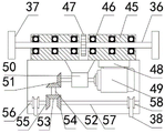
FIG. 4 is a view of the lift structure of the present invention;
FIG. 5 is a bottom view of the gripper of the present invention;
FIG. 6 is a view of the structure of the processing mechanism of the present invention;
FIG. 7 is an enlarged view of a portion of the present invention A.
In the figure: 1. a feeding mechanism; 2. a processing mechanism; 3. a guide rail; 4. a base; 5. a guide wheel; 6. a vertical rod; 7. a transverse plate; 8. a translation motor; 9. a lifting mechanism; 10. a gripper; 11. a drive motor; 12. a first electrical box; 13. a first decelerator; 14. a first V-belt; 15. an ARM processor; 16. a velocimeter; 17. a first coupling; 18. a first rotating shaft; 19. a first gear; 20. a first guide wheel; 21. a second gear; 22. a first drive shaft; 23. a third gear; 24. a second rotating shaft; 25. a second guide wheel; 26. a brake; 27. a brake pad; 28. a second electrical box; 29. a first drive sprocket; 30. a first chain; 31. a first driven sprocket; 32. a second decelerator; 33. a second coupling; 34. a second drive sprocket; 35. a second chain; 36. a third rotating shaft; 37. a third guide wheel; 38. a first cable; 39. a first fixing plate; 40. rotating the steering engine; 41. a fixed block; 42. a telescopic rod; 43. a splint; 44. anti-skid blocks; 45. a suspension block; 46. a rolling bearing; 47. a second driven sprocket; 48. a base; 49. a first lift motor; 50. a third speed reducer; 51. a fourth gear; 52. a second drive shaft; 53. a fifth gear; 54. a sixth gear; 55. a seventh gear; 56. a third drive shaft; 57. a fourth drive shaft; 58. a winding wheel; 59. an infrared detector; 60. a cutting chamber; 61. water jet; 62. a posture adjusting plate; 63. cutting the extrusion roller; 64. a drum; 65. a waste bin; 66. A first treatment tank; 67. a second treatment tank; 68. a second lift motor; 69. a water pump; 70. a fixed mount 71, a transformer 72, a second cable; 73. a second fixing plate; 74. a wire; 75. a water pipe; 76. a positive electrode metal recovery rod; 77. an ion exchange membrane; 78. a negative metal recovery rod; 79. a first filter screen; 80. a second filter screen; 81. a guide wheel.
Detailed Description
As shown in fig. 1 to 7, the following technical solutions are adopted in the present embodiment: the utility model provides a recovery unit is disassembled to car battery, includes feed mechanism 1 and processing mechanism 2, feed mechanism 1 includes base 4, montant 6, diaphragm 7, elevating system 9 and gripper 10, 4 downside of base is equipped with guide pulley 5 and is connected with the transmission of guide rail 3, guide pulley 5 includes first guide pulley 20 and second guide pulley 25, first guide pulley 20 is fixed in first pivot 18 one end, the first pivot 18 other end is connected with first reduction gear 13 output shaft through first shaft coupling 17, first pivot 18 is close to first shaft coupling 17 one end and is equipped with first gear 19, first gear 19 is connected with first transmission 22 one end meshing through second gear 21, the first pivot 22 other end is connected with third gear 23 meshing through another second gear 21, third gear 23 is fixed in second pivot 24 side, 24 left end of second pivot is equipped with brake block 27, brake block 27 and the cooperation of stopper 26 are connected, the 24 other ends of second pivot and 25 fixed connection of second guide pulley, first reduction gear 13 output pivot department is equipped with tachymeter 16, tachymeter 16 and ARM treater 15 signal connection, just ARM treater 15 sets up between driving motor 11 and first reduction gear 13, driving motor 11 and first reduction gear 13 are connected through the transmission of first V belt 14, driving motor 11 is through first electric box 12 and power electric connection, just driving motor 11 and ARM treater 15 signal connection.
The top ends of the bases 4 on the two guide rails 3 are fixedly connected with the vertical rods 6, the top ends of the two vertical rods 6 are respectively fixedly connected with the front end and the rear end of the transverse plate 7, the front end of the upper side of the transverse plate 7 is fixedly connected with the translation motor 8, the translation motor 8 is electrically connected with the power supply through the second electric box 28, the end part of the rotating shaft of the translation motor 8 is fixedly connected with the first driving sprocket 29, the first driving sprocket 29 is in transmission connection with the first driven sprocket 31 through the first chain 30, the first driven sprocket 31 is fixed at one end of the input rotating shaft of the second speed reducer 32, the second speed reducer 32 is fixed at the upper side of the cavity of the transverse plate 7, the output rotating shaft of the second speed reducer 32 is in rotation connection with the second driving sprocket 34 through the second coupler 33, the auxiliary sprocket is arranged on the transverse plate 7 far away from one side of the second driving sprocket 34, and the second, the second chain 35 is in transmission connection with a second driven chain wheel 47 on the lifting mechanism 9, the second driven chain wheel 47 is fixed in the middle of the third rotating shaft 36, third guide wheels 37 are arranged at two ends of the third rotating shaft 36, and the third guide wheels 37 are in transmission connection with a track on the transverse plate 7.
The third rotating shaft 36 of the lifting mechanism 9 is rotatably connected with the suspension block 45 through a plurality of rolling bearings 46, the lower end of the suspension block 45 is fixedly connected with a third reducer 50 and is fixedly connected with a first lifting motor 49 through a base 48, the first lifting motor 49 is electrically connected with a power supply, the rotating shaft of the first lifting motor 49 is rotatably connected with the third reducer 50, the third reducer 50 is rotatably connected with a fourth gear 51, the fourth gear 51 is meshed and connected with one end of a second transmission shaft 52 through a fifth gear 53, the other end of the second transmission shaft 52 is respectively meshed and connected with a sixth gear 54 and a seventh gear 55 through another fifth gear 53, the seventh gear 55 is rotatably connected with a third transmission shaft 56, a winding wheel 58 is arranged on the third transmission shaft 56, the sixth gear 54 is rotatably connected with a fourth transmission shaft 57, a winding wheel 58 is arranged on the fourth transmission shaft 57, the reel 58 is provided with first cables 38, the other ends of the two first cables 38 are fixedly connected with a first fixing plate 39, and the lower side of the first fixing plate 39 is rotatably connected with a fixing block 41 of the gripper 10 through a rotary steering engine 40.
The gripper 10 comprises a fixing block 41, an expansion link 42 and a clamping plate 43, wherein four side surfaces of the fixing block 41 are respectively fixedly connected with the bottom end of the expansion link 42, and the top end of the expansion link 42 is fixedly connected with the clamping plate 43.
Processing apparatus 2 includes cutting chamber 60, refuse tank 65, first processing case 66 and second processing case 67, evenly be equipped with a plurality of water knives 61 in the cutting chamber 60, cutting chamber 60 downside is equipped with gesture adjusting plate 62, gesture adjusting plate 62 downside is equipped with cutting squeeze roll 63, cutting squeeze roll 63 below is equipped with one row of cylinder 64, be equipped with heating resistor in the cylinder 64, and with power electric connection, cylinder 64 leads to first processing case 66 to the left bank, just cylinder 64 downside is refuse tank 65, first processing case 66 bottom side is equipped with the opening and handles case 67 with the second and link up, just the opening part is equipped with second filter screen 80, is equipped with the valve in the second filter screen 80.
Above the first processing box 66, the side wall of the processing mechanism 2 is fixedly connected with a second fixing plate 73, a transformer 71, a fixing frame 70, a water pump 69 and a second lifting motor 68 are sequentially arranged on the second fixing plate 73 from left to right, the transformer 71, the water pump 69 and the second lifting motor 68 are all electrically connected with a power supply, the fixing frame 70 is fixedly connected with one end of a second cable 72, the second cable 72 passes through a guide wheel 81 on a first filter screen 79 at the bottom side of the first processing box 66 and is fixedly connected with a rotating shaft of the second lifting motor 68, a through hole is arranged on the left side of the first filter screen 79, one end of a water pipe 75 is respectively connected with the bottoms of the first processing box (66) and the second processing box (67) through the through hole, a valve is arranged at the bottom connection part, the other end of the water pump 69 is connected with a through hole, the positive pole and the negative pole of the transformer 71 are respectively electrically connected with a positive metal recovery rod 76, the positive electrode metal recovery rod 76 and the negative electrode metal recovery rod 78 are separated by an ion exchange membrane 77. The infrared detectors 59 are arranged on the bottom side surfaces of the fixing block 41 and the clamping plate 43, and the anti-skid blocks 44 are arranged on the inner side surface of the clamping plate 43.
The working principle is as follows: when the invention works, the guide wheel 5 reciprocates left and right on the track 3, the lifting mechanism 9 reciprocates back and forth on the transverse plate 7 to adjust the position of the mechanical claw 10, the infrared detector 59 positions the placed automobile battery, then the lifting mechanism 9 adjusts the mechanical claw 10 to descend to grab the battery, the battery is placed in the cutting chamber 60, the water knife 61 cuts the battery, the cut battery is extruded by the cutting and extruding roller 63 and falls onto the roller 64, after the roller heats the battery under the action of the power supply, the plastic shell of the battery is melted under the action of high temperature and becomes liquid to flow into the waste box 65, the metal impurities of the battery enter the first processing box 66 to be dissolved under the treatment of acid in the first processing box 66, the impurities left after the metal with recycling value is decomposed by the acid are filtered by the first filter screen 79, the acid of the processed waste battery enters the second processing box 67 to be electrolyzed, recovering the material in the treating liquid under the action of electrolysis.
While there have been shown and described what are at present considered to be the fundamental principles of the invention and its essential features and advantages, it will be understood by those skilled in the art that the invention is not limited by the embodiments described above, which are merely illustrative of the principles of the invention, but that various changes and modifications may be made therein without departing from the spirit and scope of the invention as defined by the appended claims and their equivalents.