CN109227667B - Cutting and grinding device for decorative board construction - Google Patents
Cutting and grinding device for decorative board construction Download PDFInfo
- Publication number
- CN109227667B CN109227667B CN201811005251.3A CN201811005251A CN109227667B CN 109227667 B CN109227667 B CN 109227667B CN 201811005251 A CN201811005251 A CN 201811005251A CN 109227667 B CN109227667 B CN 109227667B
- Authority
- CN
- China
- Prior art keywords
- supporting
- assembly
- polishing
- decorative
- cutting
- Prior art date
- Legal status (The legal status is an assumption and is not a legal conclusion. Google has not performed a legal analysis and makes no representation as to the accuracy of the status listed.)
- Expired - Fee Related
Links
- 238000010276 construction Methods 0.000 title claims abstract description 19
- 238000005498 polishing Methods 0.000 claims abstract description 82
- 238000003825 pressing Methods 0.000 claims description 20
- 230000008878 coupling Effects 0.000 claims description 6
- 238000010168 coupling process Methods 0.000 claims description 6
- 238000005859 coupling reaction Methods 0.000 claims description 6
- 230000000694 effects Effects 0.000 description 3
- 238000007517 polishing process Methods 0.000 description 2
- 101000623895 Bos taurus Mucin-15 Proteins 0.000 description 1
- 230000004075 alteration Effects 0.000 description 1
- 230000009286 beneficial effect Effects 0.000 description 1
- 238000005034 decoration Methods 0.000 description 1
- 230000006872 improvement Effects 0.000 description 1
- 238000009434 installation Methods 0.000 description 1
- 230000004048 modification Effects 0.000 description 1
- 238000012986 modification Methods 0.000 description 1
- 238000005457 optimization Methods 0.000 description 1
- 230000001681 protective effect Effects 0.000 description 1
- 238000006467 substitution reaction Methods 0.000 description 1
- 230000007306 turnover Effects 0.000 description 1
Images



Classifications
-
- B—PERFORMING OPERATIONS; TRANSPORTING
- B26—HAND CUTTING TOOLS; CUTTING; SEVERING
- B26D—CUTTING; DETAILS COMMON TO MACHINES FOR PERFORATING, PUNCHING, CUTTING-OUT, STAMPING-OUT OR SEVERING
- B26D1/00—Cutting through work characterised by the nature or movement of the cutting member or particular materials not otherwise provided for; Apparatus or machines therefor; Cutting members therefor
- B26D1/01—Cutting through work characterised by the nature or movement of the cutting member or particular materials not otherwise provided for; Apparatus or machines therefor; Cutting members therefor involving a cutting member which does not travel with the work
- B26D1/12—Cutting through work characterised by the nature or movement of the cutting member or particular materials not otherwise provided for; Apparatus or machines therefor; Cutting members therefor involving a cutting member which does not travel with the work having a cutting member moving about an axis
- B26D1/14—Cutting through work characterised by the nature or movement of the cutting member or particular materials not otherwise provided for; Apparatus or machines therefor; Cutting members therefor involving a cutting member which does not travel with the work having a cutting member moving about an axis with a circular cutting member, e.g. disc cutter
- B26D1/157—Cutting through work characterised by the nature or movement of the cutting member or particular materials not otherwise provided for; Apparatus or machines therefor; Cutting members therefor involving a cutting member which does not travel with the work having a cutting member moving about an axis with a circular cutting member, e.g. disc cutter rotating about a movable axis
- B26D1/18—Cutting through work characterised by the nature or movement of the cutting member or particular materials not otherwise provided for; Apparatus or machines therefor; Cutting members therefor involving a cutting member which does not travel with the work having a cutting member moving about an axis with a circular cutting member, e.g. disc cutter rotating about a movable axis mounted on a movable carriage
-
- B—PERFORMING OPERATIONS; TRANSPORTING
- B24—GRINDING; POLISHING
- B24B—MACHINES, DEVICES, OR PROCESSES FOR GRINDING OR POLISHING; DRESSING OR CONDITIONING OF ABRADING SURFACES; FEEDING OF GRINDING, POLISHING, OR LAPPING AGENTS
- B24B27/00—Other grinding machines or devices
- B24B27/0076—Other grinding machines or devices grinding machines comprising two or more grinding tools
-
- B—PERFORMING OPERATIONS; TRANSPORTING
- B24—GRINDING; POLISHING
- B24B—MACHINES, DEVICES, OR PROCESSES FOR GRINDING OR POLISHING; DRESSING OR CONDITIONING OF ABRADING SURFACES; FEEDING OF GRINDING, POLISHING, OR LAPPING AGENTS
- B24B41/00—Component parts such as frames, beds, carriages, headstocks
- B24B41/04—Headstocks; Working-spindles; Features relating thereto
- B24B41/042—Balancing mechanisms
-
- B—PERFORMING OPERATIONS; TRANSPORTING
- B24—GRINDING; POLISHING
- B24B—MACHINES, DEVICES, OR PROCESSES FOR GRINDING OR POLISHING; DRESSING OR CONDITIONING OF ABRADING SURFACES; FEEDING OF GRINDING, POLISHING, OR LAPPING AGENTS
- B24B41/00—Component parts such as frames, beds, carriages, headstocks
- B24B41/04—Headstocks; Working-spindles; Features relating thereto
- B24B41/047—Grinding heads for working on plane surfaces
-
- B—PERFORMING OPERATIONS; TRANSPORTING
- B24—GRINDING; POLISHING
- B24B—MACHINES, DEVICES, OR PROCESSES FOR GRINDING OR POLISHING; DRESSING OR CONDITIONING OF ABRADING SURFACES; FEEDING OF GRINDING, POLISHING, OR LAPPING AGENTS
- B24B41/00—Component parts such as frames, beds, carriages, headstocks
- B24B41/06—Work supports, e.g. adjustable steadies
-
- B—PERFORMING OPERATIONS; TRANSPORTING
- B24—GRINDING; POLISHING
- B24B—MACHINES, DEVICES, OR PROCESSES FOR GRINDING OR POLISHING; DRESSING OR CONDITIONING OF ABRADING SURFACES; FEEDING OF GRINDING, POLISHING, OR LAPPING AGENTS
- B24B7/00—Machines or devices designed for grinding plane surfaces on work, including polishing plane glass surfaces; Accessories therefor
- B24B7/10—Single-purpose machines or devices
- B24B7/16—Single-purpose machines or devices for grinding end-faces, e.g. of gauges, rollers, nuts, piston rings
- B24B7/17—Single-purpose machines or devices for grinding end-faces, e.g. of gauges, rollers, nuts, piston rings for simultaneously grinding opposite and parallel end faces, e.g. double disc grinders
-
- B—PERFORMING OPERATIONS; TRANSPORTING
- B26—HAND CUTTING TOOLS; CUTTING; SEVERING
- B26D—CUTTING; DETAILS COMMON TO MACHINES FOR PERFORATING, PUNCHING, CUTTING-OUT, STAMPING-OUT OR SEVERING
- B26D5/00—Arrangements for operating and controlling machines or devices for cutting, cutting-out, stamping-out, punching, perforating, or severing by means other than cutting
- B26D5/08—Means for actuating the cutting member to effect the cut
-
- B—PERFORMING OPERATIONS; TRANSPORTING
- B26—HAND CUTTING TOOLS; CUTTING; SEVERING
- B26D—CUTTING; DETAILS COMMON TO MACHINES FOR PERFORATING, PUNCHING, CUTTING-OUT, STAMPING-OUT OR SEVERING
- B26D7/00—Details of apparatus for cutting, cutting-out, stamping-out, punching, perforating, or severing by means other than cutting
- B26D7/22—Safety devices specially adapted for cutting machines
Landscapes
- Engineering & Computer Science (AREA)
- Mechanical Engineering (AREA)
- Life Sciences & Earth Sciences (AREA)
- Forests & Forestry (AREA)
- Finish Polishing, Edge Sharpening, And Grinding By Specific Grinding Devices (AREA)
Abstract
The invention discloses a cutting and polishing device for decorative board construction, which can rapidly polish the upper surface and the lower surface of a decorative board, has high polishing efficiency, simultaneously supports the decorative board on a clamping and positioning guide assembly, can polish and move the decorative board only by pushing the decorative board to move along the length direction by hands during polishing, can obtain the polished decorative board with required specification and length only by cutting the decorative board by using a cutting assembly after polishing to the required length, has stable support and stable motion during polishing, can rapidly polish and cut the decorative board, can adapt to the clamping and polishing of decorative boards with different thicknesses, can be adjusted according to the width of the decorative board, can adapt to the requirements of decorative boards with different widths, and has strong applicability, is suitable for construction occasions of various decorative plates.
Description
Technical Field
The invention relates to a cutting and polishing device for decorative plate construction, and belongs to the technical field of decorative plate auxiliary construction equipment.
Background
At present, with the continuous improvement of decoration quality of people, decorative plates are applied more and more. To the decorative board, when decorating, in order to guarantee decorative quality and pleasing to the eye, when decorative board installation with cut, generally need polish the decorative board, and present polishing generally adopts the manual operation polisher to go on, this kind of mode need polish each face of decorative board, when the decorative board is heavier, polishing and turn-over of decorative board are very troublesome, and, after polishing, carry again and cut to the cutting machine on, this kind of mode intensity of labour is very big, and, the effect of polishing and the precision of cutting are all not ideal, the efficiency of the cutting of polishing is influenced, simultaneously, to polishing cutting quality.
Aiming at the problems, the invention provides a cutting and polishing device for decorative plate construction, which can greatly improve the polishing effect and cutting precision of decorative plates and reduce the labor intensity.
Disclosure of Invention
In order to achieve the purpose, the invention provides the following technical scheme: the cutting and polishing device for decorative board construction comprises a first supporting component, a second supporting component, a clamping and positioning guide component, an upper polishing component, a lower polishing component and a cutting component, wherein the first supporting component and the second supporting component are respectively arranged at two ends of the decorative board to be polished and cut in the width direction, the distance between the first supporting component and the second supporting component is adjustable so as to adapt to the requirements of decorative boards with different widths, the upper parts of the first supporting component and the second supporting component are provided with the clamping and positioning guide components which are oppositely arranged, the clamping and positioning guide components can adapt to the clamping and guiding movement of decorative boards with different thicknesses, the clamping and positioning guide components are used for clamping and guiding the width edge of the decorative board to be cut and polished, the upper polishing component is connected and arranged above the decorative board to be cut and polished on the first supporting component, the lower polishing component is arranged below the to-be-cut polishing decorative plate on the first supporting component in a connected mode, and the cutting component is arranged in front of the to-be-cut polishing decorative plate in the length direction in a connected mode or in front of the second supporting component in the connected mode.
Further, as a preferred choice, the clamping and positioning guide assembly comprises a fixed seat, a lower fixed support assembly, an upper fixed plate, a movable pressing limit assembly, an adjusting nut, a connecting screw rod, a guide rod and a guide sleeve, wherein the fixed seat is fixedly arranged on the support assembly I or the support assembly II in a vertically extending manner, the lower end of the fixed seat is horizontally and fixedly connected with the lower fixed support assembly, the top of the fixed seat is provided with the upper fixed plate in a horizontally extending manner, the fixed seat is provided with the movable pressing limit assembly which is positioned between the lower fixed support assembly and the upper fixed plate in a vertically sliding manner, the top of the pressing limit assembly is fixedly connected with the connecting screw rod and the guide rod which are vertically and upwardly extending, the connecting screw rod upwardly extends out of the connecting hole of the upper fixed plate, and the lower end face of the adjusting nut in threaded connection with the connecting screw rod abuts against the upper end face, the upper fixing plate is provided with a guide sleeve matched with the guide rod in a guide mode, the position, corresponding to the guide rod, of the upper fixing plate is adjusted through rotating the adjusting nut, the distance between the lower fixing support assembly and the movable pressing limiting assembly is adjusted, and the decorative plate to be clamped is limited between the lower fixing support assembly and the movable pressing limiting assembly.
Further, as preferred, lower fixed stay subassembly compresses tightly spacing subassembly with the activity and all includes backup pad, back shaft and rotation wheel, the back shaft horizontally stretches into in the backup pad, the backup pad is provided with a plurality of race in its horizontal direction array, be provided with in the race and install and just can wind the axis pivoted rotation wheel of back shaft at the back shaft, the outer circumference terminal surface that rotates the wheel stretches out the upper surface or the lower surface of backup pad, it supports the decorative board to rotate the wheel to be convenient for remove the decorative board.
Further, as preferred, the end of the movable pressing limiting component is provided with a sliding seat, and the sliding seat can slide up and down on the fixed seat for adjustment.
Further, as preferred, the supporting component I and the supporting component II have the same structure and respectively comprise a rack, a supporting seat and a movable supporting wheel, the bottom of the rack is provided with a plurality of movable supporting wheels, the top of the rack is provided with the supporting seat, the clamping and positioning guide component is fixed on the side wall of the supporting seat, and the rack is of a frame structure.
Further, as the preferred, the top of supporting seat of supporting component one or supporting component two is provided with the upper prop that vertical direction extends, an organic whole is provided with the extension end perpendicular to it on the upper prop, go up the removable connection setting of subassembly of polishing on the extension end.
Further, as preferred, go up the subassembly of polishing and include joint support seat, bracing piece, slide, adjust cylinder one and elasticity piece of polishing, wherein, the one end of joint support seat is connected extend to serve, the last fixed being provided with of joint support seat adjust cylinder one, the other end connection of joint support seat is provided with the bracing piece, elasticity piece of polishing is fixed on the slide, the slide can along bracing piece sliding arrangement, the slide is connected adjust cylinder one's piston end, through adjust cylinder one adjusts the position of slide, the piece of polishing of elasticity piece lower extreme supports and leans on the decorative board up end of waiting to cut and polish.
Further, as preferred, the subassembly of polishing down includes adjust cylinder two, support guide pin bushing, carriage release lever and elasticity piece of polishing, the setting that support guide pin bushing can reciprocate is in the one end that is close to support component two of the frame of support component one, the setting that adjust cylinder two can reciprocate is in one of keeping away from support component two of the frame of support component one is served, it is provided with to connect on the piston rod of adjust cylinder two the carriage release lever, the carriage release lever passes but support guide pin bushing's guiding hole horizontal slip sets up, the tip of carriage release lever sets up the elasticity piece of polishing, the polishing dish of elasticity piece of polishing supports and leans on waiting to cut the lower terminal surface of the decorative board of polishing.
Further, as preferred, elasticity piece of polishing includes grinding motor, shaft coupling, connection pad, vertical disc, spring, removal dish and the dish of polishing, wherein, grinding motor's output passes through the shaft coupling is connected to the central point of connection pad puts, the outer periphery edge department of connection pad extends fixedly connected with vertical disc, be provided with the removal dish that can reciprocate in the vertical disc, remove the dish with nonrotatable setting between the vertical disc, remove the dish with be provided with many between the connection pad the spring, removable being provided with on the terminal surface of keeping away from the spring of removal dish the dish of polishing.
Further, as the optimization, the cutting assembly comprises a cutting saw, a cutting motor and a transverse moving assembly, the cutting saw is driven by the cutting motor to rotate, and the transverse moving assembly controls the cutting saw to move in the width direction of the decorative plate to be cut, so that the cutting of the decorative plate to be cut is realized.
Compared with the prior art, the invention has the beneficial effects that:
the decorative board cutting and polishing device can rapidly polish the upper surface and the lower surface of the decorative board at the same time, has high polishing efficiency, meanwhile, the decorative plate is supported on the clamping and positioning guide assembly, and only the decorative plate needs to be pushed by hand to move along the length direction of the decorative plate when being polished, the polishing movement of the decorative plate can be realized, when the decorative plate is polished to the required length, the decorative plate is cut only by utilizing the cutting assembly, the polished decorative plate with the required specification and length can be obtained, the support is stable and the motion is stable in the polishing process, the polishing and cutting treatment of the decorative plate can be rapidly realized, meanwhile, the clamping, positioning and guiding assembly of the invention can adapt to the clamping and polishing of decorative plates with different thicknesses, in addition, the invention can be adjusted according to the width of the decorative plate, meets the requirements of decorative plates with different widths, has strong applicability and is suitable for construction occasions of various decorative plates.
Drawings
FIG. 1 is a schematic top view of a cutting and polishing device for decorative board construction according to the present invention;
FIG. 2 is a schematic structural view of a cutting and polishing device for decorative board construction according to the present invention;
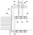
FIG. 3 is a schematic structural view of a clamping, positioning and guiding assembly of the cutting and polishing device for decorative board construction of the present invention;
FIG. 4 is a schematic structural view of an elastic polishing member of the cutting and polishing device for decorative panel construction according to the present invention;
Detailed Description
The technical solutions in the embodiments of the present invention will be clearly and completely described below with reference to the drawings in the embodiments of the present invention, and it is obvious that the described embodiments are only a part of the embodiments of the present invention, and not all of the embodiments. All other embodiments, which can be derived by a person skilled in the art from the embodiments given herein without making any creative effort, shall fall within the protection scope of the present invention.
Referring to fig. 1-4, the present invention provides a technical solution: cutting and grinding device for decorative board construction comprises a first supporting component 14, a second supporting component 21, a clamping and positioning guide component 2, an upper grinding component 3, a lower grinding component and a cutting component, wherein the first supporting component 14 and the second supporting component 21 are respectively arranged at two ends of the decorative board to be ground and cut in the width direction, the distance between the first supporting component 14 and the second supporting component 21 is adjustable so as to meet the requirements of decorative boards with different widths, the clamping and positioning guide components 2 which are oppositely arranged are arranged on the upper portions of the first supporting component 14 and the second supporting component 21, the clamping and positioning guide components 2 can adapt to clamping and guiding movement of decorative boards with different thicknesses, the clamping and positioning guide components 2 are used for clamping and guiding the width edges of the decorative board to be ground and cut, the upper grinding component 3 is connected and arranged above the decorative board to be ground and cut on the first supporting component 14, the lower polishing assembly is connected and arranged below the decorative plate to be cut and polished on the supporting assembly I14, and the cutting assembly is connected and arranged in front of the decorative plate to be cut and polished in the length direction or in front of the supporting assembly I or the supporting assembly II.
In this embodiment, as shown in fig. 3, the clamping, positioning and guiding assembly includes a fixing base 25, a lower fixing and supporting assembly 26, an upper fixing plate 27, a movable pressing and limiting assembly 29, an adjusting nut 33, a connecting screw 34, a guiding rod 35 and a guiding sleeve 36, wherein the fixing base 25 is fixedly disposed on the supporting assembly one or the supporting assembly two in a vertically extending manner, the lower end of the fixing base 25 is horizontally and fixedly connected with the lower fixing and supporting assembly 26, the top of the fixing base 25 is provided with the upper fixing plate 27 in a horizontally extending manner, the fixing base 25 is provided with the movable pressing and limiting assembly 29 between the lower fixing and the upper fixing plate in a vertically sliding manner, the top of the pressing and limiting assembly 29 is fixedly connected with the connecting screw 34 and the guiding rod 35 in a vertically extending manner, the connecting screw 34 extends upwards out of the connecting hole of the upper fixing plate 27, and the lower end face of an adjusting nut 33 in threaded connection on the connecting screw rod 34 is abutted against the upper end face of the upper fixing plate 27, a guide sleeve 36 which is matched with the guide rod 35 in a guide way is arranged at a position, corresponding to the guide rod 35, on the upper fixing plate 27, the adjustment of the distance between the lower fixed supporting component and the movable pressing limiting component is realized by rotating the adjusting nut 33, and the decorative plate to be clamped is limited between the lower fixed supporting component and the movable pressing limiting component.
As a preferred embodiment, as shown in fig. 3, the lower fixed supporting assembly and the movable pressing limiting assembly each include a supporting plate, a supporting shaft 30 and a rotating wheel 31, the supporting shaft 30 horizontally extends into the supporting plate, the supporting plate is provided with a plurality of wheel grooves in a horizontal direction array, the wheel grooves are internally provided with the rotating wheels 31 which are mounted on the supporting shaft 30 by bearings 32 and can rotate around the axis of the supporting shaft, the outer circumferential end surfaces of the rotating wheels 31 extend out of the upper surface or the lower surface of the supporting plate, and the rotating wheels 31 support the decorative plate so as to move the decorative plate.
The end part of the movable pressing limiting component is provided with a sliding seat 28, and the sliding seat 28 can be adjusted on the fixed seat in a vertical sliding mode.
As shown in fig. 1, the first support assembly and the second support assembly have the same structure and each include a frame, a support seat 1 and a movable support wheel 17, the bottom of the frame is provided with a plurality of movable support wheels 17, the top of the frame is provided with the support seat 1, the clamping and positioning guide assembly is fixed on the side wall of the support seat 1, and the frame is of a frame structure.
The top of supporting seat of supporting component one or supporting component two is provided with the upper prop 9 that vertical direction extends, an organic whole is provided with the perpendicular extension end with it on the upper prop 9, go up the removable connection setting of subassembly of polishing and be in extend and serve.
As shown in fig. 2, the upper polishing assembly comprises a connection support seat 23, a support rod 4, a slide seat 24, a first adjusting cylinder 10 and an elastic polishing piece, wherein one end of the connection support seat 23 is connected to the extension end, the first adjusting cylinder 10 is fixedly arranged on the connection support seat 23, the support rod 4 is connected to the other end of the connection support seat 23, the elastic polishing piece is fixed on the slide seat 24, the slide seat 24 can be arranged along the support rod 4 in a sliding manner, the slide seat 24 is connected to the piston end of the first adjusting cylinder 10, the position of the slide seat is adjusted through the first adjusting cylinder 10, and a polishing disc at the lower end of the elastic polishing piece abuts against the upper end face of a decorative board to be cut and polished.
The lower polishing assembly comprises a second adjusting cylinder 15, a second supporting guide sleeve 16, a moving rod 18 and an elastic polishing piece, the second supporting guide sleeve 16 can be arranged at one end, close to the second supporting assembly, of the first supporting assembly, the second adjusting cylinder 15 can be arranged at one end, far away from the second supporting assembly, of the first supporting assembly, the moving rod 18 is connected to the piston rod of the second adjusting cylinder 15, the moving rod 18 penetrates through a guide hole of the first supporting guide sleeve 16 and can be arranged in a horizontal sliding mode, the end portion of the moving rod 18 is provided with the elastic polishing piece, and a polishing disc of the elastic polishing piece abuts against the lower end face of the decorative plate to be cut and polished.
Elastic grinding member includes grinding motor 11, shaft coupling 12, connection pad 37, vertical disc 38, spring 40, removal dish 41 and grinding disk 39, wherein, grinding motor 11's output passes through shaft coupling 12 is connected to the central point of connection pad 37 puts, the outer periphery edge of connection pad 37 extends fixedly connected with vertical disc 38, be provided with the removal dish 41 that can reciprocate in the vertical disc 38, remove dish 41 with can not rotate the setting between the vertical disc 38, remove dish 41 with be provided with many between the connection pad 37 spring 40, removable being provided with on the terminal surface of keeping away from the spring of removal dish 41 grinding disk 39.
In addition, the cutting assembly comprises a cutting saw 6, a cutting motor 8 and a transverse moving assembly 5, the cutting saw 6 is driven by the cutting motor 8 to rotate, the transverse moving assembly controls the cutting saw to move in the width direction of the decorative plate to be cut so as to cut the decorative plate, and protective covers 7 are arranged on two sides of the cutting saw.
The decorative board cutting and polishing device can rapidly polish the upper surface and the lower surface of the decorative board at the same time, has high polishing efficiency, meanwhile, the decorative plate is supported on the clamping and positioning guide assembly, and only the decorative plate needs to be pushed by hand to move along the length direction of the decorative plate when being polished, the polishing movement of the decorative plate can be realized, when the decorative plate is polished to the required length, the decorative plate is cut only by utilizing the cutting assembly, the polished decorative plate with the required specification and length can be obtained, the support is stable and the motion is stable in the polishing process, the polishing and cutting treatment of the decorative plate can be rapidly realized, meanwhile, the clamping, positioning and guiding assembly of the invention can adapt to the clamping and polishing of decorative plates with different thicknesses, in addition, the invention can be adjusted according to the width of the decorative plate, meets the requirements of decorative plates with different widths, has strong applicability and is suitable for construction occasions of various decorative plates.
Although embodiments of the present invention have been shown and described, it will be appreciated by those skilled in the art that changes, modifications, substitutions and alterations can be made in these embodiments without departing from the principles and spirit of the invention, the scope of which is defined in the appended claims and their equivalents.
Claims (4)
1. The cutting and polishing device for decorative board construction is characterized by comprising a first supporting component, a second supporting component, a clamping and positioning guide component, an upper polishing component, a lower polishing component and a cutting component, wherein the first supporting component and the second supporting component are respectively arranged at two ends of the decorative board to be polished and cut in the width direction, the distance between the first supporting component and the second supporting component is adjustable so as to adapt to the requirements of decorative boards with different widths, the upper parts of the first supporting component and the second supporting component are provided with the clamping and positioning guide components which are oppositely arranged, the clamping and positioning guide components can adapt to the clamping and guiding movement of decorative boards with different thicknesses, the clamping and positioning guide components are used for clamping and guiding the width edge of the decorative board to be cut and polished, the upper polishing component is connected and arranged above the decorative board to be cut and polished on the first supporting component, the lower grinding assembly is connected and arranged below the decorative plate to be cut and ground on the first support assembly, and the cutting assembly is connected and arranged in front of the decorative plate to be cut and ground in the length direction on the first support assembly or the second support assembly;
the clamping, positioning and guiding assembly comprises a fixed seat, a lower fixed supporting assembly, an upper fixed plate, a movable pressing and limiting assembly, an adjusting nut, a connecting screw rod, a guide rod and a guide sleeve, wherein the fixed seat extending in the vertical direction is fixedly arranged on the first supporting assembly or the second supporting assembly, the lower end of the fixed seat is horizontally and fixedly connected with the lower fixed supporting assembly, the top of the fixed seat is provided with the upper fixed plate extending in the horizontal direction, the movable pressing and limiting assembly positioned between the lower fixed supporting assembly and the upper fixed plate is arranged on the fixed seat in a vertically sliding manner, the top of the pressing and limiting assembly is fixedly connected with the connecting screw rod and the guide rod extending vertically and upwards, the connecting screw rod extends upwards out of a connecting hole of the upper fixed plate, and the lower end face of the adjusting nut in threaded connection on the connecting screw rod is abutted against the upper end face, a guide sleeve which is in guide fit with the guide rod is arranged on the upper fixing plate at a position corresponding to the guide rod, the adjustment of the distance between the lower fixed supporting assembly and the movable pressing limiting assembly is realized by rotating the adjusting nut, and the decorative plate to be clamped is limited between the lower fixed supporting assembly and the movable pressing limiting assembly;
the lower fixed supporting assembly and the movable pressing limiting assembly respectively comprise a supporting plate, a supporting shaft and rotating wheels, the supporting shaft horizontally extends into the supporting plate, a plurality of wheel grooves are formed in the supporting plate in an array mode in the horizontal direction, the rotating wheels which are installed on the supporting shaft and can rotate around the axis of the supporting shaft are arranged in the wheel grooves, the outer circumferential end faces of the rotating wheels extend out of the upper surface or the lower surface of the supporting plate, and the rotating wheels support the decorative plate so as to move the decorative plate;
an upper support column extending in the vertical direction is arranged at the top of the supporting seat of the supporting assembly I or the supporting assembly II, an extending end perpendicular to the upper support column is integrally arranged on the upper support column, and the upper grinding assembly is detachably connected to the extending end;
the upper polishing assembly comprises a connecting support seat, a support rod, a sliding seat, a first adjusting cylinder and an elastic polishing piece, wherein one end of the connecting support seat is connected to the extending end, the first adjusting cylinder is fixedly arranged on the connecting support seat, the other end of the connecting support seat is provided with the support rod in a connecting manner, the elastic polishing piece is fixed on the sliding seat, the sliding seat can be arranged along the support rod in a sliding manner, the sliding seat is connected to the piston end of the first adjusting cylinder, the position of the sliding seat is adjusted through the first adjusting cylinder, and a polishing disc at the lower end of the elastic polishing piece abuts against the upper end face of a decorative plate to be cut and polished;
the lower polishing assembly comprises a second adjusting cylinder, a second supporting guide sleeve, a moving rod and an elastic polishing piece, the second supporting guide sleeve is arranged at one end, close to the second supporting assembly, of the rack of the first supporting assembly in a vertically movable mode, the second adjusting cylinder is arranged at one end, far away from the second supporting assembly, of the rack of the first supporting assembly in a vertically movable mode, the moving rod is connected to a piston rod of the second adjusting cylinder, the moving rod penetrates through a guide hole of the first supporting guide sleeve in a horizontally sliding mode, the elastic polishing piece is arranged at the end portion of the moving rod, and a polishing disc of the elastic polishing piece abuts against the lower end face of a to-be-cut polished decorative plate;
elastic polishing piece includes polishing motor, shaft coupling, connection pad, vertical disc, spring, removal dish and the mill of polishing, wherein, polishing motor's output passes through the shaft coupling is connected to the central point of connection pad puts, the outer periphery edge department of connection pad extends fixedly connected with vertical disc, be provided with the removal dish that can reciprocate in the vertical disc, remove the dish with nonrotation sets up between the vertical disc, remove the dish with be provided with many between the connection pad the spring, removable being provided with on the terminal surface of keeping away from the spring of removal dish the mill of polishing.
2. The cutting and grinding device for decorative panel construction according to claim 1, characterized in that: the end part of the movable pressing limiting component is provided with a sliding seat, and the sliding seat is arranged on the fixed seat and can be adjusted in a vertical sliding mode.
3. The cutting and grinding device for decorative panel construction according to claim 1, characterized in that: the first supporting assembly and the second supporting assembly are identical in structure and respectively comprise a rack, a supporting seat and a movable supporting wheel, the bottom of the rack is provided with a plurality of movable supporting wheels, the supporting seat is arranged at the top of the rack, the clamping and positioning guide assembly is fixed on the side wall of the supporting seat, and the rack is of a frame structure.
4. The cutting and grinding device for decorative panel construction according to claim 1, characterized in that: the cutting assembly comprises a cutting saw, a cutting motor and a transverse moving assembly, the cutting saw is driven by the cutting motor to rotate, and the transverse moving assembly controls the cutting saw to move in the width direction of the decorative plate to be cut so as to cut the decorative plate.
Priority Applications (1)
| Application Number | Priority Date | Filing Date | Title |
|---|---|---|---|
| CN201811005251.3A CN109227667B (en) | 2018-08-30 | 2018-08-30 | Cutting and grinding device for decorative board construction |
Applications Claiming Priority (1)
| Application Number | Priority Date | Filing Date | Title |
|---|---|---|---|
| CN201811005251.3A CN109227667B (en) | 2018-08-30 | 2018-08-30 | Cutting and grinding device for decorative board construction |
Publications (2)
| Publication Number | Publication Date |
|---|---|
| CN109227667A CN109227667A (en) | 2019-01-18 |
| CN109227667B true CN109227667B (en) | 2020-12-29 |
Family
ID=65068991
Family Applications (1)
| Application Number | Title | Priority Date | Filing Date |
|---|---|---|---|
| CN201811005251.3A Expired - Fee Related CN109227667B (en) | 2018-08-30 | 2018-08-30 | Cutting and grinding device for decorative board construction |
Country Status (1)
| Country | Link |
|---|---|
| CN (1) | CN109227667B (en) |
Families Citing this family (12)
| Publication number | Priority date | Publication date | Assignee | Title |
|---|---|---|---|---|
| CN110587420A (en) * | 2019-10-25 | 2019-12-20 | 湖南达时精密塑胶模具有限公司 | Production equipment for processing water surface plate |
| CN110757320A (en) * | 2019-12-11 | 2020-02-07 | 湖北华品科技发展有限公司 | Copper strips removes oxide layer device for photovoltaic module |
| CN111571413B (en) * | 2020-06-02 | 2021-04-27 | 重庆水利电力职业技术学院 | Automatic burnishing device of ornamental material processing usefulness |
| CN112045740A (en) * | 2020-08-09 | 2020-12-08 | 应嘉迪 | Plastics cutting platform of moulding plastics convenient to upset material |
| CN112571221A (en) * | 2020-12-12 | 2021-03-30 | 安徽卓尔航空科技有限公司 | Screw surface grinding device |
| CN112692934A (en) * | 2020-12-23 | 2021-04-23 | 李海超 | Integrated cutting and polishing device suitable for floors with different thicknesses |
| CN113305915B (en) * | 2021-05-27 | 2022-10-21 | 安徽杰蓝特新材料有限公司 | PE solid wall pipe cutting equipment with fixed knot constructs |
| CN114310509B (en) * | 2021-12-30 | 2025-06-17 | 苏州诺富微电子有限公司 | A gallium arsenide wafer horizontal cutting device |
| CN114347185A (en) * | 2021-12-30 | 2022-04-15 | 邓曼 | Synchronous cutting and end surface polishing device for building materials and using method thereof |
| CN115488749A (en) * | 2022-11-08 | 2022-12-20 | 常州喷丝板厂有限公司 | Polishing and grinding machine for machining high-performance carbon fiber spinneret plate |
| CN118123651A (en) * | 2024-04-17 | 2024-06-04 | 漳州市芗城区长鑫家具有限公司 | An automatic grinding production line for wood products |
| CN120920926A (en) * | 2025-08-26 | 2025-11-11 | 泰州市一瑾机械有限公司 | Gear laser cutting device for hardware cutting |
Citations (6)
| Publication number | Priority date | Publication date | Assignee | Title |
|---|---|---|---|---|
| JP2015160250A (en) * | 2014-02-26 | 2015-09-07 | 光洋機械工業株式会社 | Double-head surface grinding method and double-head surface grinding machine |
| CN105643709A (en) * | 2016-03-14 | 2016-06-08 | 湖州中辰建设有限公司 | Clamp used for cutting thermal insulating decorative board |
| CN206084748U (en) * | 2016-09-18 | 2017-04-12 | 兴科电子科技有限公司 | elastic grinding head |
| CN206998549U (en) * | 2017-07-04 | 2018-02-13 | 苏州亨达尔工业材料有限公司 | A kind of sheet material double face synchronization burnishing device |
| CN206998486U (en) * | 2017-07-26 | 2018-02-13 | 烟台职业学院 | A kind of two-sided sanding apparatus of grinding tool manufacture |
| CN108453598A (en) * | 2018-03-02 | 2018-08-28 | 汤蒙琪 | A kind of machinery iron lumber surface bilayer synchronizes polissoir |
Family Cites Families (4)
| Publication number | Priority date | Publication date | Assignee | Title |
|---|---|---|---|---|
| JP5717303B1 (en) * | 2013-11-15 | 2015-05-13 | 大昌精機株式会社 | Horizontal double-sided surface grinding machine |
| JP6407773B2 (en) * | 2015-03-13 | 2018-10-17 | 日本碍子株式会社 | Honeycomb structure manufacturing method and grinding wheel |
| CN204504922U (en) * | 2015-04-02 | 2015-07-29 | 贺尔碧格阀业(常州)有限公司 | A kind of can the grinding structure of Double face grinding |
| CN106312769B (en) * | 2016-09-23 | 2018-12-07 | 山东大学 | A kind of two-sided grinding device for gas flame cuttiug plate |
-
2018
- 2018-08-30 CN CN201811005251.3A patent/CN109227667B/en not_active Expired - Fee Related
Patent Citations (6)
| Publication number | Priority date | Publication date | Assignee | Title |
|---|---|---|---|---|
| JP2015160250A (en) * | 2014-02-26 | 2015-09-07 | 光洋機械工業株式会社 | Double-head surface grinding method and double-head surface grinding machine |
| CN105643709A (en) * | 2016-03-14 | 2016-06-08 | 湖州中辰建设有限公司 | Clamp used for cutting thermal insulating decorative board |
| CN206084748U (en) * | 2016-09-18 | 2017-04-12 | 兴科电子科技有限公司 | elastic grinding head |
| CN206998549U (en) * | 2017-07-04 | 2018-02-13 | 苏州亨达尔工业材料有限公司 | A kind of sheet material double face synchronization burnishing device |
| CN206998486U (en) * | 2017-07-26 | 2018-02-13 | 烟台职业学院 | A kind of two-sided sanding apparatus of grinding tool manufacture |
| CN108453598A (en) * | 2018-03-02 | 2018-08-28 | 汤蒙琪 | A kind of machinery iron lumber surface bilayer synchronizes polissoir |
Also Published As
| Publication number | Publication date |
|---|---|
| CN109227667A (en) | 2019-01-18 |
Similar Documents
| Publication | Publication Date | Title |
|---|---|---|
| CN109227667A (en) | Decorative panel construction cutting grinding device | |
| CN204397569U (en) | A kind of belt sander of fine-tuning abrasive band | |
| CN205685193U (en) | A kind of Novel rotary trimming device | |
| CN212665630U (en) | Prevent grinding device for plywood of work piece dislocation | |
| CN116572020A (en) | A continuous finishing device for elongated channel steel | |
| CN217017111U (en) | Rotary spraying device for hardware processing | |
| CN220312736U (en) | Cutter grinding device with variable grinding angle | |
| CN216463784U (en) | Auxiliary polishing frame of angle grinder | |
| CN117340730A (en) | Edge chamfering equipment for wood chopping board processing | |
| CN214080566U (en) | Automatic plane grinding machine | |
| CN211565440U (en) | Adjustable multi-angle polishing device | |
| CN218551465U (en) | Processing, trimming and fixing equipment for sports cap | |
| CN102744747B (en) | Semi-automatic wood lathe | |
| CN209970465U (en) | Surface grinding machine for bearing convenient to fix a position | |
| CN221269883U (en) | Saw blade sharpening device for saw blade machining | |
| CN215847629U (en) | Positioning mechanism for toothless circular saw blade polishing machine | |
| CN218697540U (en) | Guiding mechanism of fishing rod water mill device | |
| CN214817236U (en) | Plastic steel window glass surface equipment of polishing | |
| CN223981595U (en) | A trimmer for aluminum profile alloy processing | |
| CN213731033U (en) | Polishing equipment for production of hardware of communication equipment | |
| CN223012666U (en) | Auxiliary knife sharpening machine | |
| CN210938495U (en) | Edge grinding machine for stone processing | |
| CN112518544B (en) | Movable polishing machine | |
| CN220699131U (en) | Full-automatic grinding device | |
| CN218592622U (en) | Abrasive machine is used in processing of shoes material auxiliary material |
Legal Events
| Date | Code | Title | Description |
|---|---|---|---|
| PB01 | Publication | ||
| PB01 | Publication | ||
| SE01 | Entry into force of request for substantive examination | ||
| SE01 | Entry into force of request for substantive examination | ||
| CB03 | Change of inventor or designer information | ||
| CB03 | Change of inventor or designer information |
Inventor after: Quan Feng Inventor after: Yang Shifu Inventor before: Quan Feng |
|
| GR01 | Patent grant | ||
| GR01 | Patent grant | ||
| CF01 | Termination of patent right due to non-payment of annual fee | ||
| CF01 | Termination of patent right due to non-payment of annual fee |
Granted publication date: 20201229 |