CN109160002B - Method for recycling cigarette carton wrapper - Google Patents
Method for recycling cigarette carton wrapper Download PDFInfo
- Publication number
- CN109160002B CN109160002B CN201811398811.6A CN201811398811A CN109160002B CN 109160002 B CN109160002 B CN 109160002B CN 201811398811 A CN201811398811 A CN 201811398811A CN 109160002 B CN109160002 B CN 109160002B
- Authority
- CN
- China
- Prior art keywords
- conveying
- frame
- box
- pressing
- baffle
- Prior art date
- Legal status (The legal status is an assumption and is not a legal conclusion. Google has not performed a legal analysis and makes no representation as to the accuracy of the status listed.)
- Active
Links
- 235000019504 cigarettes Nutrition 0.000 title claims abstract description 58
- 238000000034 method Methods 0.000 title claims abstract description 24
- 238000004064 recycling Methods 0.000 title claims abstract description 19
- 238000007731 hot pressing Methods 0.000 claims abstract description 51
- 238000005452 bending Methods 0.000 claims abstract description 33
- 238000004806 packaging method and process Methods 0.000 claims abstract description 19
- 238000004519 manufacturing process Methods 0.000 claims abstract description 14
- 238000007493 shaping process Methods 0.000 claims abstract description 14
- 238000007789 sealing Methods 0.000 claims abstract description 11
- 239000000463 material Substances 0.000 claims description 87
- 230000007246 mechanism Effects 0.000 claims description 76
- 238000003825 pressing Methods 0.000 claims description 48
- 238000010438 heat treatment Methods 0.000 claims description 30
- 230000000712 assembly Effects 0.000 claims description 11
- 238000000429 assembly Methods 0.000 claims description 11
- 230000009471 action Effects 0.000 claims description 6
- 229910000831 Steel Inorganic materials 0.000 claims description 3
- 239000010959 steel Substances 0.000 claims description 3
- 230000006835 compression Effects 0.000 claims description 2
- 238000007906 compression Methods 0.000 claims description 2
- 241000252254 Catostomidae Species 0.000 claims 2
- 210000001503 joint Anatomy 0.000 claims 2
- QNRATNLHPGXHMA-XZHTYLCXSA-N (r)-(6-ethoxyquinolin-4-yl)-[(2s,4s,5r)-5-ethyl-1-azabicyclo[2.2.2]octan-2-yl]methanol;hydrochloride Chemical group Cl.C([C@H]([C@H](C1)CC)C2)CN1[C@@H]2[C@H](O)C1=CC=NC2=CC=C(OCC)C=C21 QNRATNLHPGXHMA-XZHTYLCXSA-N 0.000 claims 1
- 230000006978 adaptation Effects 0.000 claims 1
- 239000010985 leather Substances 0.000 claims 1
- 230000001133 acceleration Effects 0.000 description 17
- 238000010586 diagram Methods 0.000 description 8
- 230000008569 process Effects 0.000 description 6
- 230000000694 effects Effects 0.000 description 4
- 239000003292 glue Substances 0.000 description 3
- 238000012546 transfer Methods 0.000 description 3
- 244000176261 Viburnum cassinoides Species 0.000 description 2
- 238000013461 design Methods 0.000 description 2
- 238000006073 displacement reaction Methods 0.000 description 2
- 238000007639 printing Methods 0.000 description 2
- 238000012545 processing Methods 0.000 description 2
- 238000003860 storage Methods 0.000 description 2
- 230000009286 beneficial effect Effects 0.000 description 1
- 230000000903 blocking effect Effects 0.000 description 1
- 230000008859 change Effects 0.000 description 1
- 238000006243 chemical reaction Methods 0.000 description 1
- 230000005484 gravity Effects 0.000 description 1
- 239000013072 incoming material Substances 0.000 description 1
- 230000003993 interaction Effects 0.000 description 1
- 238000012423 maintenance Methods 0.000 description 1
- 230000004048 modification Effects 0.000 description 1
- 238000012986 modification Methods 0.000 description 1
- 238000012858 packaging process Methods 0.000 description 1
- 230000033764 rhythmic process Effects 0.000 description 1
- 238000001179 sorption measurement Methods 0.000 description 1
Images



Classifications
-
- B—PERFORMING OPERATIONS; TRANSPORTING
- B65—CONVEYING; PACKING; STORING; HANDLING THIN OR FILAMENTARY MATERIAL
- B65B—MACHINES, APPARATUS OR DEVICES FOR, OR METHODS OF, PACKAGING ARTICLES OR MATERIALS; UNPACKING
- B65B61/00—Auxiliary devices, not otherwise provided for, for operating on sheets, blanks, webs, binding material, containers or packages
-
- B—PERFORMING OPERATIONS; TRANSPORTING
- B65—CONVEYING; PACKING; STORING; HANDLING THIN OR FILAMENTARY MATERIAL
- B65H—HANDLING THIN OR FILAMENTARY MATERIAL, e.g. SHEETS, WEBS, CABLES
- B65H29/00—Delivering or advancing articles from machines; Advancing articles to or into piles
- B65H29/16—Delivering or advancing articles from machines; Advancing articles to or into piles by contact of one face only with moving tapes, bands, or chains
- B65H29/18—Delivering or advancing articles from machines; Advancing articles to or into piles by contact of one face only with moving tapes, bands, or chains and introducing into a pile
-
- B—PERFORMING OPERATIONS; TRANSPORTING
- B65—CONVEYING; PACKING; STORING; HANDLING THIN OR FILAMENTARY MATERIAL
- B65H—HANDLING THIN OR FILAMENTARY MATERIAL, e.g. SHEETS, WEBS, CABLES
- B65H3/00—Separating articles from piles
- B65H3/08—Separating articles from piles using pneumatic force
- B65H3/0808—Suction grippers
- B65H3/085—Suction grippers separating from the bottom of pile
-
- B—PERFORMING OPERATIONS; TRANSPORTING
- B65—CONVEYING; PACKING; STORING; HANDLING THIN OR FILAMENTARY MATERIAL
- B65H—HANDLING THIN OR FILAMENTARY MATERIAL, e.g. SHEETS, WEBS, CABLES
- B65H31/00—Pile receivers
- B65H31/04—Pile receivers with movable end support arranged to recede as pile accumulates
- B65H31/08—Pile receivers with movable end support arranged to recede as pile accumulates the articles being piled one above another
- B65H31/10—Pile receivers with movable end support arranged to recede as pile accumulates the articles being piled one above another and applied at the top of the pile
-
- B—PERFORMING OPERATIONS; TRANSPORTING
- B65—CONVEYING; PACKING; STORING; HANDLING THIN OR FILAMENTARY MATERIAL
- B65H—HANDLING THIN OR FILAMENTARY MATERIAL, e.g. SHEETS, WEBS, CABLES
- B65H5/00—Feeding articles separated from piles; Feeding articles to machines
- B65H5/22—Feeding articles separated from piles; Feeding articles to machines by air-blast or suction device
- B65H5/222—Feeding articles separated from piles; Feeding articles to machines by air-blast or suction device by suction devices
- B65H5/224—Feeding articles separated from piles; Feeding articles to machines by air-blast or suction device by suction devices by suction belts
-
- B—PERFORMING OPERATIONS; TRANSPORTING
- B65—CONVEYING; PACKING; STORING; HANDLING THIN OR FILAMENTARY MATERIAL
- B65H—HANDLING THIN OR FILAMENTARY MATERIAL, e.g. SHEETS, WEBS, CABLES
- B65H5/00—Feeding articles separated from piles; Feeding articles to machines
- B65H5/36—Article guides or smoothers, e.g. movable in operation
-
- B—PERFORMING OPERATIONS; TRANSPORTING
- B65—CONVEYING; PACKING; STORING; HANDLING THIN OR FILAMENTARY MATERIAL
- B65H—HANDLING THIN OR FILAMENTARY MATERIAL, e.g. SHEETS, WEBS, CABLES
- B65H2701/00—Handled material; Storage means
- B65H2701/10—Handled articles or webs
- B65H2701/11—Dimensional aspect of article or web
- B65H2701/113—Size
- B65H2701/1131—Size of sheets
Landscapes
- Engineering & Computer Science (AREA)
- Mechanical Engineering (AREA)
- Control And Other Processes For Unpacking Of Materials (AREA)
Abstract
Description
技术领域technical field
本发明涉及卷烟条盒皮循环利用技术领域,尤其涉及一种卷烟条盒皮循环使用方法。The invention relates to the technical field of cigarette rod casing recycling, in particular to a cigarette rod casing recycling method.
背景技术Background technique
在手工封烟装条盒的生产过程中,大多数卷烟厂采用包装机生产出的标准小包通过条烟包装时使用白盒皮不点胶并用条包透明纸进行外包装,到手工封烟装条盒时把白盒皮拆开收集。为了节约成本,白盒皮一般要进行循环二次或三次使用,但使用过的条盒皮在包装机上由于已经经过一次包装过程,白盒皮产生变形很难二次使用,所以在二次使用前必须进行整平。In the production process of hand-sealed cigarette packs, most cigarette factories use standard small packs produced by packaging machines to pack cigarettes with white box skins without dispensing glue and wrap transparent paper for outer packaging. When the box is opened, the white box skin is disassembled and collected. In order to save costs, the white box skin is generally used twice or three times in a cycle, but the used carton skin has already undergone a packaging process on the packaging machine, and the deformation of the white box skin is difficult to use again. must be leveled before.
而针对白盒皮的整平,目前并无专门的设备可用。虽然存在一些纸张压平设备,但其并不能适用于变形后白盒皮的整平。For the leveling of white box skins, there is currently no special equipment available. Although there are some paper flattening devices, they are not suitable for flattening the white box skin after deformation.
如CN207986272U的实用新型专利就公开了一种烟盒印刷生产线纸张压平装置,其通过设置有螺纹柱和第一固定块,且在第一固定块上均铰接有连接杆,连接杆的另一端均铰接有固定块,转动圆盘手轮时,使得固定块底部的安装板下降,从而实现对纸张的压紧,通过在安装板内设有螺纹杆和驱动电机,驱动电机工作时,使得螺纹杆上的第二活动块水平移动,方便压辊在纸张上来回压紧,使得纸张的平整效果更好,通过在工作台的安装腔内水平放置有电热管,在纸张压平的同时对纸张加热,方便烟盒在印刷时将图文转印到纸张上。For example, the utility model patent of CN207986272U discloses a paper flattening device for a cigarette case printing production line, which is provided with a threaded column and a first fixing block, and a connecting rod is hinged on the first fixing block, and the other end of the connecting rod is connected. Both are hinged with a fixed block. When the disc handwheel is rotated, the mounting plate at the bottom of the fixed block is lowered, so as to realize the pressing of the paper. By installing a threaded rod and a driving motor in the mounting plate, when the driving motor works, the thread The second movable block on the rod moves horizontally, which is convenient for the pressing roller to press back and forth on the paper, so that the paper leveling effect is better. Heating, it is convenient for the cigarette case to transfer the pictures and texts to the paper during printing.
该压平设备只适用于烟盒成型前成卷纸张的压平,而对于使用后的白盒皮,由于其上存有变形及折痕,现有的压平设备很难满足整平要求。The flattening equipment is only suitable for flattening the rolled paper before the cigarette case is formed, and the existing flattening equipment is difficult to meet the flattening requirements due to the deformation and creases on the white box skin after use.
目前针对手工封烟装条盒的生产过程中白盒皮循环使用的客观需求,一直使用人工整理并重力压平,时间长又浪费人力,与行业降本增效的理念不符。At present, in view of the objective demand for the recycling of white box skins in the production process of hand-sealed cigarette boxes, manual sorting and gravity flattening have been used all the time, which takes a long time and wastes manpower, which is inconsistent with the industry's concept of reducing costs and increasing efficiency.
发明内容SUMMARY OF THE INVENTION
本发明的目的在于提供一种卷烟条盒皮循环使用方法。The purpose of the present invention is to provide a cigarette rod casing recycling method.
为解决上述技术问题,本发明采用如下技术方案:In order to solve the above-mentioned technical problems, the present invention adopts the following technical solutions:
一种卷烟条盒皮循环使用方法,包括以下步骤:A cigarette rod casing recycling method, comprising the following steps:
(1)对包装机生产线生产出的标准小包进行条烟包装,采用白盒皮不点胶并用条包透明纸进行外包装;(1) The standard packets produced by the packaging machine production line are packaged with sticks of cigarettes, using white box skins without dispensing glue and wrapping transparent paper for outer packaging;
(2)白盒皮包装后的条烟送至手工封烟车间,将条烟拆开,对标准小包手工封烟装条,并对白盒皮进行收集;(2) The cigarettes packed in the white box are sent to the hand-sealing workshop, the cigarettes are disassembled, the standard packets are manually sealed, and the white box is collected;
(3)将收集的白盒皮转运到卷烟条盒皮自动整平定型收集系统进行热压及反向折弯处理后实现整平;(3) Transfer the collected white box skins to the automatic flattening and shaping collection system for cigarette rod skins for hot pressing and reverse bending to achieve flattening;
(4)整平处理后的白盒皮再次转运到包装机生产线再次使用。(4) The flattened white box skin is transferred to the packaging machine production line again for reuse.
所述步骤(3)使用的卷烟条盒皮自动整平定型收集系统包括取料装置、自动整平热压装置、加速输送装置和收料整理装置;The cigarette rod casing automatic leveling and shaping collection system used in the step (3) includes a reclaiming device, an automatic leveling and hot pressing device, an accelerated conveying device and a material receiving and finishing device;
取料装置由料库、输送结构和单张取料结构组成;The reclaiming device consists of a material storehouse, a conveying structure and a single-sheet reclaiming structure;
料库位于输送结构的上方,其用于放置待处理的盒皮;The magazine is located above the conveying structure, which is used to place the boxes to be processed;
输送结构的输送方向与上方料库内盒皮的长折线方向相平行,设定输送结构的输送方向为由右至左;输送结构包括输送机架及布置在输送机架上的吸风皮带,且吸风皮带做步进式输送;The conveying direction of the conveying structure is parallel to the direction of the long folding line of the box skin in the upper warehouse, and the conveying direction of the conveying structure is set to be from right to left; the conveying structure includes a conveying frame and a suction belt arranged on the conveying frame. And the suction belt is used for step-by-step conveying;
单张取料结构布置于料库的下方,其用于单张抓取盒皮,并将其放置于输送结构上;单张取料结构包括下料控制机构、吸盘机构和推料机构,下料控制机构包括分别位于料库下方并分别位于盒皮放置区左右两侧的左挡板和右挡板,左挡板和右挡板均沿前后方向延伸布置,并分别通过支架架设在输送机架上方;其中左挡板与对应的支架转动连接,并通过下料驱动装置实现往复摆动;其中右挡板与对应的支架固定连接;The single-sheet reclaiming structure is arranged below the material warehouse, which is used to grab the box skin and place it on the conveying structure; the single-sheet reclaiming structure includes a blanking control mechanism, a suction cup mechanism and a pushing mechanism. The material control mechanism includes a left baffle and a right baffle located under the material storehouse and respectively located on the left and right sides of the box skin placement area. The left baffle is rotatably connected with the corresponding bracket, and the reciprocating swing is realized by the blanking drive device; the right baffle is fixedly connected with the corresponding bracket;
吸盘机构包括至少两列吸盘组件,对应列的吸盘组件位于吸风皮带两侧的间隙处,并沉入输送机架设置;The suction cup mechanism includes at least two rows of suction cup assemblies, the suction cup assemblies of the corresponding row are located at the gaps on both sides of the suction belt, and are set in the conveyor frame;
推料机构位于单张取料结构的右侧,其包括沿左右方向布置的推料气缸和连接在推料气缸活塞杆端的推料板;推料板指向左侧,并在推料气缸作业用下由右挡板与输送机架之间的间隙处往复伸缩;The pushing mechanism is located on the right side of the single-sheet reclaiming structure, which includes a pushing cylinder arranged in the left-right direction and a pushing plate connected to the end of the piston rod of the pushing cylinder; the pushing plate points to the left and is used for the operation of the pushing cylinder. The bottom is reciprocating and retracting from the gap between the right baffle and the conveyor frame;
自动整平热压装置架设在输送结构上方,并位于取料装置的左侧位置处,料库中的盒皮由单张取料结构取出放置到输送结构上,并在输送结构的输送下运至自动整平热压装置处步进式停留;The automatic leveling and hot pressing device is erected above the conveying structure and is located at the left position of the reclaiming device. Step-by-step stop at the automatic leveling and hot-pressing device;
自动整平热压装置包括位于输送结构正上方的加热体、用于推动加热体往复升降的热压驱动机构以及对加热体往复升降起导向作用的热压导向机构;The automatic leveling hot-pressing device includes a heating body located directly above the conveying structure, a hot-pressing driving mechanism for pushing the heating body to reciprocate and lift, and a hot-pressing guiding mechanism for guiding the reciprocating lifting of the heating body;
加速输送装置接于输送结构的左侧,用于接受经输送结构输送过来的盒皮并对其加速输送;加速输送装置包括加速皮带输送机、输送压辊机构和反向折弯机构,加速皮带输送机的输送方向与输送结构相重合,且加速皮带输送机的右端设有加速接料机构;The acceleration conveying device is connected to the left side of the conveying structure, and is used to receive the box skins conveyed by the conveying structure and accelerate the conveying; The conveying direction of the conveyor coincides with the conveying structure, and the right end of the accelerating belt conveyor is provided with an accelerating material receiving mechanism;
输送压辊机构包括在加速皮带输送机输送面上方沿左右方向间隔排布的输送压辊组件,每个输送压辊组件均包括架设固定在加速皮带输送机机架上的压辊轴,压辊轴上沿其长度方向间隔布置至少两个输送压轮;The conveying pressure roller mechanism includes conveying pressure roller assemblies arranged at intervals in the left and right direction above the conveying surface of the accelerating belt conveyor. At least two conveying pinch rollers are arranged on the shaft at intervals along its length direction;
反向折弯机构包括折弯导向翘板组件和折痕压辊组件,折弯导向翘板组件包括设于加速皮带输送机的左端并分别位于加速皮带输送机前后两侧的折弯导向翘板;折弯导向翘板与加速皮带输送机机架固定连接,且右端与加速皮带输送机的皮带部对接,左端向加速皮带输送机的中线收缩并翘起在输送面上方;The reverse bending mechanism includes a bending guide rocker assembly and a crease pressure roller assembly. The bending guide rocker assembly includes a bending guide rocker set at the left end of the acceleration belt conveyor and located on the front and rear sides of the acceleration belt conveyor respectively. ;The bending guide rocker is fixedly connected with the frame of the accelerating belt conveyor, and the right end is butted with the belt part of the accelerating belt conveyor, and the left end is retracted toward the center line of the accelerating belt conveyor and raised above the conveying surface;
折痕压辊组件包括架设固定在加速皮带输送机机架上的压辊轴,压辊轴上沿其长度方向间隔布置折痕压轮,折痕压轮的数量及位置与待处理的盒皮上的长折线的位置及数量一一对应;The creasing and pressing roller assembly includes a pressing roller shaft that is erected and fixed on the frame of the accelerated belt conveyor. The pressing roller shaft is spaced along its length direction with creasing and pressing rollers. The positions and quantities of the long polylines on the line correspond one-to-one;
收料整理装置设于加速输送装置的左侧,包括收料机架、收料仓和成摞导出机构,经加速输送装置单张输送来的盒皮被导向输送到收料仓中并成摞收集,收集到预定数量后移到成摞导出机构上导出。The receiving and finishing device is located on the left side of the accelerating conveying device, including the receiving rack, the receiving bin and the stacking export mechanism. The box skins conveyed by the accelerating conveying device are guided and transported to the receiving bin and formed into a stack. Collect, collect a predetermined amount and move it to a stack exporting mechanism for export.
所述料库包括料库框架及设于料库框架内侧的导料结构,导料结构由与盒皮侧边对应的库侧板和与盒皮顶角对应的库角板组成,库侧板和库角板均与料库框架固定连接,库侧板和库角板围合形成的区域即为盒皮放置区;料库框架的下侧固设有用于支撑盒皮的支撑角;The material warehouse includes a material warehouse frame and a material guide structure arranged inside the material warehouse frame. The material guide structure is composed of a warehouse side plate corresponding to the side of the box skin and a warehouse corner plate corresponding to the top corner of the box skin. Both the corner plate and the corner plate of the warehouse are fixedly connected with the frame of the warehouse, and the area enclosed by the side plate of the warehouse and the corner plate of the warehouse is the box skin placement area; the lower side of the warehouse frame is fixed with a supporting angle for supporting the box skin;
库角板为立式布置的90°角钢,库角板顶部向外扩散延伸形成入料导向结构;库侧板为立式布置的条板;支撑角分设于料库框架的四周并均向料库中心凸出设置,且四周的支撑角均位于同一水平高度,每个支撑角均向下倾斜。The corner plate of the warehouse is a vertically arranged 90° angle steel. The top of the corner plate of the warehouse spreads outward to form a feeding guide structure; The center of the library is set protrudingly, and the surrounding support angles are all at the same level, and each support angle is inclined downward.
所述取料装置中每列吸盘组件均包括沿左右方向布置的吸盘安装架和在吸盘安装架上排布设置的吸盘,吸盘的吸口均朝向上方料库设置;吸盘安装架的下方连接有吸盘升降结构,以控制吸盘组件升降;吸盘组件在吸盘升降结构作用下升起至高位时,吸盘组件的吸盘吸附到料库中最底侧的一张盒皮;吸盘组件在吸盘升降结构作用下下降起至低位时,吸附的盒皮随之移动放置到输送结构的吸风皮带上。Each row of suction cup assemblies in the reclaiming device includes a suction cup mounting frame arranged in the left-right direction and suction cups arranged on the suction cup mounting frame, and the suction ports of the suction cups are all set towards the upper material warehouse; the suction cups are connected below the suction cup mounting frame. Lifting structure to control the lifting and lowering of the suction cup assembly; when the suction cup assembly rises to a high position under the action of the suction cup lifting structure, the suction cup of the suction cup assembly is adsorbed to the bottommost box in the material warehouse; the suction cup assembly descends under the action of the suction cup lifting structure When it reaches the low position, the adsorbed box skin is moved and placed on the suction belt of the conveying structure.
所述自动整平热压装置中热压导向机构包括与加热体固定连接并分别朝前后方向伸出的支撑臂,且支撑臂在加热体的左右侧对称布置有两条,输送机架上与支撑臂对应处分别固定有导向座,导向座内设有与其在竖向方向上滑动配合的导向柱,导向柱向上与对应的支撑臂固定连接;The hot-pressing guide mechanism in the automatic leveling hot-pressing device includes support arms that are fixedly connected to the heating body and protrude in the front and rear directions respectively, and two supporting arms are symmetrically arranged on the left and right sides of the heating body. Corresponding parts of the support arms are respectively fixed with guide seats, and guide columns are arranged in the guide seats to slide and cooperate with them in the vertical direction, and the guide columns are upwardly fixed and connected with the corresponding support arms;
热压驱动机构包括设于加热体上方的热压升降气缸,热压升降气缸通过支撑架固定在输送机架上,且热压升降气缸的活塞杆端与加热体固定连接;支撑架上位于热压升降气缸的两侧分别设有拉杆通孔,拉杆通孔内设有竖向布置并与其滑动配合的拉杆,拉杆的下端与加热体固定连接,拉杆的上端固设有挡圈;当热压升降气缸推动加热体与输送结构上盒皮热压接触时,拉杆上的挡圈与支撑架抵接;The hot-pressing driving mechanism includes a hot-pressing lifting cylinder arranged above the heating body, the hot-pressing lifting cylinder is fixed on the conveying frame through a support frame, and the piston rod end of the hot-pressing lifting cylinder is fixedly connected with the heating body; There are tie rod through holes on both sides of the pressure lifting cylinder, and the tie rod through holes are provided with tie rods arranged vertically and slidably matched with them, the lower end of the tie rod is fixedly connected with the heating body, and the upper end of the tie rod is fixed with a retaining ring; When the lifting cylinder pushes the heating body to contact with the upper box skin of the conveying structure under hot pressure, the retaining ring on the tie rod is in contact with the support frame;
支撑架包括沿前后方向布置的气缸安装板,气缸安装板的两端分别固定连接有向下延伸的中支撑板,中支撑板的下端与输送机架固定连接。The support frame includes a cylinder mounting plate arranged along the front and rear directions, two ends of the cylinder mounting plate are respectively fixedly connected with a downwardly extending middle support plate, and the lower end of the middle support plate is fixedly connected with the conveying frame.
所述加速输送装置中的加速接料机构包括设于加速皮带输送机的右端并分别位于加速皮带输送机前后两侧的接料槽,接料槽与加速皮带输送机机架固定连接,且两接料槽的槽口相对设置;接料槽的左端与加速皮带输送机的皮带部对接,右端向外水平倾斜并扩口;两个接料槽配合形成进口大、出口小的接料结构;The accelerated material receiving mechanism in the accelerated conveying device comprises a material receiving trough which is arranged on the right end of the accelerating belt conveyor and is respectively located on the front and rear sides of the accelerating belt conveyor. The grooves of the feeding chute are arranged oppositely; the left end of the feeding chute is butted with the belt part of the accelerating belt conveyor, and the right end is horizontally inclined outward and flared; the two feeding grooves cooperate to form a feeding structure with a large inlet and a small outlet;
所述输送压轮和折痕压轮均由压轮架和压轮体组成,压轮架与对应的压辊轴连接,压轮体安装在压轮架上并可转动;The conveying pressing roller and the crease pressing roller are composed of a pressing roller frame and a pressing roller body, the pressing roller frame is connected with the corresponding pressing roller shaft, and the pressing roller body is installed on the pressing roller frame and can be rotated;
所述输送压轮的压轮体为圆柱形结构;所述折痕压轮的压轮体为向外周处收缩的菱形结构;The pressure roller body of the conveying pressure roller is a cylindrical structure; the pressure roller body of the crease pressure roller is a diamond-shaped structure that shrinks at the outer periphery;
所述压轮架为张力下压式结构,其包括与压辊轴连接的固定架和与压轮体连接的活动架,固定架与活动架铰接连接,且固定架与活动架之间连接有张力机构,张力机构推动活动架向下压;The pressing roller frame is a tension-pressing type structure, which includes a fixed frame connected with the pressing roller shaft and a movable frame connected with the pressing roller body, the fixed frame and the movable frame are hingedly connected, and the fixed frame and the movable frame are connected with a Tension mechanism, the tension mechanism pushes the movable frame down;
所述压轮架与压辊轴之间设有位置调整机构,位置调整结构包括在压辊轴上沿其长度方向设置的长槽,压轮架的固定架套设在压辊轴上,且该处穿过设有与其螺纹连接的位置锁定螺钉,位置锁定螺钉的端部位于长槽内并与其抵接配合。A position adjusting mechanism is arranged between the pressing roller frame and the pressing roller shaft. The position adjusting structure comprises a long groove arranged on the pressing roller shaft along its length direction, and the fixing frame of the pressing roller frame is sleeved on the pressing roller shaft, and There is a position locking screw threadedly connected with the position locking screw, and the end of the position locking screw is located in the long groove and abuts and cooperates with it.
所述收料仓安装于收料机架上,且收料机架上与加速皮带输送机左端部对应处设有入料口;The receiving bin is installed on the receiving frame, and the receiving frame is provided with a feeding port corresponding to the left end of the acceleration belt conveyor;
收料仓包括固定导向部和活动部,活动部包括立式布置的支座以及在收料机架上沿竖向设置的滑轨和升降丝杠,支座与滑轨滑动配合,并与升降丝杠的螺母座连接,升降丝杠转动驱动支座沿滑轨升降移动;支座上固定有横向凸出的支撑梁,支撑梁沿水平方向间隔排布至少两个,用于支撑进入收料仓的盒皮;The receiving bin includes a fixed guide part and a movable part, and the movable part includes a vertically arranged support, a sliding rail and a lifting screw vertically arranged on the receiving frame, and the support slidingly cooperates with the sliding rail and is connected with the lifting and lowering frame. The nut seat of the lead screw is connected, and the lifting lead screw rotates to drive the support to move up and down along the slide rail; the support is fixed with horizontally protruding support beams, and at least two support beams are arranged at intervals along the horizontal direction to support the incoming material the box skin of the warehouse;
固定导向部包括与入料口相对并分别固定在活动部相对两侧的导向挡板,分别为高导向挡板和低导向挡板,低导向挡板临近入料口设置,且其高度低于入料口,高导向挡板远离入料口设置,且其高度高于入料口; 高导向挡板和低导向挡板之间形成将盒皮导向收料仓活动部的导向定位结构。The fixed guide part includes guide baffles opposite to the feeding port and respectively fixed on opposite sides of the movable part, which are respectively a high guide baffle and a low guide baffle. For the feeding port, the high guide baffle is set far away from the feeding port, and its height is higher than the feeding port; a guide positioning structure is formed between the high guide baffle and the low guide baffle to guide the box skin to the movable part of the receiving bin.
所述成摞导出机构包括导出皮带输送机,导出皮带输送机的起始端设于入料仓的下方;导出皮带输送机的起始端延伸设有输送梁,输送梁间隔布设多个,并分别与上方收料仓中活动部的相邻支撑梁之间的间隙对应;导出皮带输送机的皮带对应输送梁设置多条;The stacking lead-out mechanism includes a lead-out belt conveyor, and the starting end of the lead-out belt conveyor is arranged below the feed bin; the lead-out end of the lead-out belt conveyor is extended with conveying beams, and a plurality of conveying beams are arranged at intervals and are respectively connected with each other. The gaps between the adjacent support beams of the movable part in the upper receiving bin correspond to the gaps; the belts leading out of the belt conveyor are set up to correspond to the conveyor beams;
收料仓收集到预定数量盒皮后,收料仓的活动部下降,其支撑梁下降至对应的输送梁之间的间隙,支撑梁携带的成摞盒皮与导出皮带输送机的皮带接触并导出;After the receiving bin collects a predetermined number of boxes, the movable part of the receiving bin is lowered, and its support beam is lowered to the gap between the corresponding conveying beams. export;
所述收料仓内还设有用于检测进入收料仓盒皮数量的计数器,计数器与升降丝杠控制连接;单张盒皮进入收料仓,计数器计数一次,并发送控制信号至升降丝杠,升降丝杠控制收料仓下移预设距离;The receiving bin is also provided with a counter for detecting the number of box skins entering the receiving bin, and the counter is controlled and connected with the lifting screw; a single box skin enters the receiving bin, the counter counts once, and sends a control signal to the lifting screw , the lifting screw controls the receiving bin to move down the preset distance;
所述收料整理装置中高导向挡板和低导向挡板的相对侧设有与盒皮形状配合的凸起定位;所述高导向挡板和低导向挡板之间还固定连接有前挡板,前挡板与高导向挡板、低导向挡板以及收料机架围合形成与盒皮现状相适配的所述固定导向部。The opposite sides of the high guide baffle and the low guide baffle in the receiving and finishing device are provided with convex positioning that matches the shape of the box skin; a front baffle is also fixedly connected between the high guide baffle and the low guide baffle , the front baffle is enclosed with the high guide baffle, the low guide baffle and the receiving frame to form the fixed guide part which is adapted to the current situation of the box skin.
所述步骤(3)中收集的白盒皮转运到卷烟条盒皮自动整平定型收集系统时,收集的盒皮成摞放置到料库中,且盒皮的外侧面朝上。When the white box skins collected in the step (3) are transferred to the automatic flattening and shaping collection system for cigarette rod skins, the collected box skins are placed in a stack and placed in the material warehouse with the outer side of the box skins facing upwards.
本发明的有益效果是:The beneficial effects of the present invention are:
本发明的卷烟条盒皮循环使用方法通过采用卷烟条盒皮自动整平定型收集系统,可实现对手工封烟人工拆开收集的白盒皮进行自动抓取、整平定型和收集整理,且盒皮整平效率高,从而可以高效地对白条盒皮进行二次或多次循环使用,节省了手工封烟条盒皮采购费用。The cigarette rod casing recycling method of the present invention can realize automatic grabbing, flattening and shaping, and collection and arrangement of the white casings collected by manual cigarette sealing by adopting an automatic flattening and shaping collection system for the cigarette casings. The casing leveling efficiency is high, so that the white rod casing can be efficiently recycled for two or more times, and the purchase cost of the manual sealing cigarette casing casing can be saved.
附图说明Description of drawings
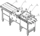
图1是本发明实施例的总装立体示意图;1 is a schematic perspective view of an assembly of an embodiment of the present invention;
图2是本发明实施例中取料装置的立体示意图;Fig. 2 is the three-dimensional schematic diagram of the reclaiming device in the embodiment of the present invention;
图3是取料装置中料库部位的立体示意图;Fig. 3 is the three-dimensional schematic diagram of the material warehouse part in the reclaiming device;
图4是图3后视方向的立体示意图;Fig. 4 is the three-dimensional schematic diagram of the rear view direction of Fig. 3;
图5是图3的仰视图;Fig. 5 is the bottom view of Fig. 3;
图6是取料装置中输送结构的立体示意图;Fig. 6 is the three-dimensional schematic diagram of the conveying structure in the reclaiming device;
图7是取料装置中吸盘机构的立体示意图;Fig. 7 is the three-dimensional schematic diagram of the suction cup mechanism in the reclaiming device;
图8是本发明实施例中自动整平热压装置的立体示意图;8 is a schematic perspective view of an automatic leveling hot-pressing device in an embodiment of the present invention;
图9是本发明实施例中加速输送装置的立体示意图;Fig. 9 is the three-dimensional schematic diagram of the accelerated conveying device in the embodiment of the present invention;
图10是图9的俯视图;Fig. 10 is the top view of Fig. 9;
图11是图9的主视图;Fig. 11 is the front view of Fig. 9;
图12是加速输送装置中位置调整机构的俯视图;Figure 12 is a top view of the position adjustment mechanism in the accelerated conveying device;
图13是加速输送装置中压轮架的主视图;Figure 13 is a front view of the pinch roller frame in the accelerated conveying device;
图14本发明实施例中收料整理装置的示意图;Figure 14 is a schematic diagram of a receiving and finishing device in an embodiment of the present invention;
图15是收料整理装置中收料机架及收料仓的立体示意图;Fig. 15 is the three-dimensional schematic diagram of the material receiving rack and the material receiving bin in the material receiving and finishing device;
图16是图15的主视图;Fig. 16 is the front view of Fig. 15;
图17是收料整理装置中成摞导出机构的立体示意图;Figure 17 is a perspective view of a stacking export mechanism in the material receiving and finishing device;
图18是本发明实施例中盒皮的俯视图;。Figure 18 is a top view of the box skin in the embodiment of the present invention;
具体实施方式Detailed ways
以下结合附图对本发明的具体实施方式作详细说明。The specific embodiments of the present invention will be described in detail below with reference to the accompanying drawings.
本实施例的一种卷烟条盒皮循环使用方法,包括以下步骤:A cigarette rod casing recycling method of the present embodiment includes the following steps:
(1)对包装机生产线生产出的标准小包进行条烟包装,采用白盒皮不点胶并用条包透明纸进行外包装;(1) The standard packets produced by the packaging machine production line are packaged with sticks of cigarettes, using white box skins without dispensing glue and wrapping transparent paper for outer packaging;
(2)白盒皮包装后的条烟送至手工封烟车间,将条烟拆开,对标准小包手工封烟装条,并对白盒皮进行收集;(2) The cigarettes packed in the white box are sent to the hand-sealing workshop, the cigarettes are disassembled, the standard packets are manually sealed, and the white box is collected;
(3)将收集的白盒皮转运到卷烟条盒皮自动整平定型收集系统进行热压及反向折弯处理后实现整平;(3) Transfer the collected white box skins to the automatic flattening and shaping collection system for cigarette rod skins for hot pressing and reverse bending to achieve flattening;
(4)整平处理后的白盒皮再次转运到包装机生产线再次使用。(4) The flattened white box skin is transferred to the packaging machine production line again for reuse.
所述步骤(3)中收集的白盒皮转运到卷烟条盒皮自动整平定型收集系统处理时,收集的盒皮成摞放置到料库中,且盒皮的外侧面朝上。When the white box skins collected in the step (3) are transferred to the automatic flattening and shaping collection system for cigarette rod skins for processing, the collected box skins are placed in a stack and placed in the material warehouse with the outer side of the box skins facing upward.
本实施例的卷烟条盒皮循环使用方法通过采用卷烟条盒皮自动整平定型收集系统,可实现对手工封烟人工拆开收集的白盒皮进行自动抓取、整平定型和收集整理,且盒皮整平效率高,从而可以高效地对白条盒皮进行二次或多次循环使用,节省了手工封烟条盒皮采购费用。The cigarette rod casing recycling method of the present embodiment can realize automatic grabbing, flattening and shaping, and collection and sorting of the white casings collected by manual cigarette sealing by adopting an automatic flattening and shaping collection system for the cigarette rod casings. In addition, the casing leveling efficiency is high, so that the white rod casing can be efficiently recycled for two or more times, and the purchase cost of the manual sealing cigarette casing casing can be saved.
所述步骤(3)使用的卷烟条盒皮自动整平定型收集系统如图1至图18所示,包括取料装置1、自动整平热压装置2、加速输送装置3、收料整理装置4和电控装置5。The cigarette rod casing automatic leveling and shaping collection system used in the step (3) is shown in Figures 1 to 18, including a reclaiming device 1, an automatic leveling and hot
如图2至图7所示,取料装置由料库11、输送结构12和单张取料结构13组成。其中料库11位于输送结构12的上方,待处理的盒皮6成摞放置到料库11中,且盒皮6的外侧面朝上设置,方便单张取料结构13作用取料;单张取料结构13布置于料库11的下方,其用于单张抓取盒皮,并将其放置于输送结构12上;输送结构12的输送方向与上方料库11内盒皮的长折线方向相平行,方便后续加工处理,三者配合可根据生产节拍自动从料库内取出单张盒皮并放置到输送结构上实现步进式间歇输送。As shown in FIG. 2 to FIG. 7 , the reclaiming device is composed of a
料库11包括料库框架111及设于料库框架111内侧的导料结构,导料结构由与盒皮侧边对应的库侧板112和与盒皮顶角对应的库角板113组成,库侧板112和库角板113均与料库框架111固定连接,库侧板112和库角板113围合形成的区域即为盒皮放置区;料库框架111的下侧固设有用于支撑盒皮的支撑角114,支撑角114分设于料库框架111的四周并均向料库中心凸出设置,且四周的支撑角均位于同一水平高度,并且每个支撑角114均向下倾斜。The
上述导料结构通过库侧板112和库角板113的配合,不仅实现对拆开盒皮的配合导向,而且能够避免盒皮在料库中再次变形。本实施例并可根据不同的盒皮规格采取直接更换料库的方式适应规格变换。The above-mentioned material guiding structure not only realizes the cooperation and guidance of the disassembled box skin, but also can prevent the box skin from being deformed again in the material warehouse through the cooperation of the
本实施例中,库角板113为立式布置的90°角钢,库角板113顶部向外扩散延伸形成入料导向结构,方便盒皮在料库的入料放置;库侧板112为立式布置的条板。In this embodiment, the
输送结构12的输送方向与上方料库11内盒皮的长折线方向相平行,设定输送结构的输送方向为由右至左;输送结构12包括输送机架122及布置在输送机架122上的吸风皮带121,吸风皮带121等间距布置有至少三条,且吸风皮带121在电机驱动下做步进式输送。吸风皮带121的设置能够实现对盒皮的紧密吸附定位,避免盒皮的输送过程中跑位。The conveying direction of the conveying
单张取料结构13布置于料库11的下方,其用于单张抓取盒皮,并将其放置于输送结构12上。单张取料结构包括下料控制机构、吸盘机构和推料机构,下料控制机构包括分别位于料库11下方并分别位于盒皮放置区左右两侧的左挡板131和右挡板132,左挡板131和右挡板132均沿前后方向延伸布置,并分别通过支架架设在输送机架上方;其中左挡板131与对应的支架转动连接,并通过下料驱动装置实现往复摆动;其中右挡板132与对应的支架固定连接。The single-
本实施例中,下料驱动装置选用气缸134,左挡板131两端通过挡板轴与对应的机架转动连接,挡板轴与气缸134的活塞杆之间通过连杆连接,以实现对左挡板131的往复摆动驱动。In this embodiment, a
工作时,左挡板131和右挡板132分别对应盒皮短折线外侧的折页,在盒皮被往下抓取时,可同时实现对该处折页的反向折弯(由于拆开盒皮是在折线处朝内侧面折弯,反向折弯处理后从而实现对盒皮的折平);同时左挡板131通过下料驱动装置进行往复摆动,盒皮在单张下料过程中,落至左、右挡板的下半部位置处,左挡板131下半部向左侧转动倾斜,使左、右挡板之间的区域变大,从而方便盒皮落料。During operation, the
并且左挡板131和右挡板132对称布置,左挡板131上半部向左侧朝上倾斜设置,右挡板132上半部向右侧朝上倾斜设置,方便盒皮被往下抓取时落料,且能更好实现反向折弯效果。And the
吸盘机构包括至少两列吸盘组件,对应列的吸盘组件位于吸风皮带121两侧的间隙123处,并沉入输送机架设置;每列吸盘组件均包括沿左右方向布置的吸盘安装架135和在吸盘安装架135上排布设置的吸盘136,吸盘136的吸口均朝向上方料库设置;吸盘安装架135的下方连接有吸盘升降结构,以控制吸盘组件升降;吸盘升降结构选用吸盘升降气缸137。The suction cup mechanism includes at least two rows of suction cup assemblies, the suction cup assemblies of the corresponding row are located at the
吸盘组件在吸盘升降结构作用下升起至高位时,吸盘组件的吸盘136吸附到料库11中最底侧的一张盒皮;吸盘组件在吸盘升降结构作用下下降起至低位时,吸附的盒皮随之移动放置到输送结构12的吸风皮带121上。该吸盘机构与输送结构相结合,不仅互不干涉,保证设备的紧凑性,且作业效率高。When the suction cup assembly rises to a high position under the action of the suction cup lifting structure, the
推料机构位于单张取料结构的右侧,其包括沿左右方向布置的推料气缸138和连接在推料气缸138活塞杆端的推料板133;推料板133指向左侧,并在推料气缸138作业用下由右挡板132与输送机架之间的间隙处往复伸缩。通过上述推料机构的设置,在盒皮落料过程中,由于右挡板132位置固定,盒皮短折线外侧的折页会搭在右挡板132上,此时推料机构伸出实现对该侧折页处的反向折弯,从而实现对盒皮该处的反向折弯。The pushing mechanism is located on the right side of the single-sheet reclaiming structure, which includes a pushing
自动整平热压装置2架设在输送结构12上方,并位于取料装置1的左侧位置处,料库11中的盒皮由单张取料结构13取出放置到输送结构12上,并在输送结构12的输送下运至自动整平热压装置处步进式停留,之后自动整平热压装置2下落并完成对盒皮的热压整平处理。The automatic leveling and hot
自动整平热压装置2包括位于输送结构12正上方的加热体21、用于推动加热体21往复升降的热压驱动机构以及对加热体往复升降起导向作用的热压导向机构。The automatic leveling hot
热压导向机构包括与加热体21固定连接并分别朝前后方向伸出的支撑臂22,且支撑臂22在加热体的左右侧对称布置有两条,输送机架122上与支撑臂22对应处分别固定有导向座23,导向座23内设有与其在竖向方向上滑动配合的导向柱24,导向柱24向上与对应的支撑臂固定连接22。热压导向机构的上述设置实现对加热体的稳固导向,保证平稳作业。The hot-pressing guide mechanism includes
热压驱动机构包括设于加热体上方的热压升降气缸25,热压升降气缸25通过支撑架26固定在输送机架上,且热压升降气缸25的活塞杆端与加热体21固定连接;支撑架26上位于热压升降气缸25的两侧分别设有拉杆通孔,拉杆通孔内设有竖向布置并与其滑动配合的拉杆27,拉杆27的下端与加热体21固定连接,拉杆27的上端固设有挡圈28;当热压升降气缸25推动加热体21与输送结构上盒皮热压接触时,拉杆27上的挡圈28与支撑架26抵接。热压驱动机构的上述设置实现了加热体21热压盒皮时的压力保证,并且拉杆27的设置避免热压体行程过大而与输送结构碰撞发生损坏。The hot-pressing driving mechanism includes a hot-pressing
本实施例中,支撑架26包括沿前后方向布置的气缸安装板,气缸安装板的两端分别固定连接有向下延伸的中支撑板,中支撑板的下端与输送机架固定连接。In this embodiment, the
加速输送装置3接于输送结构12的左侧,用于接受经输送结构12输送过来的盒皮并对其加速输送;加速输送装置3包括加速皮带输送机31(加速皮带输送机31的输送速度大于输送结构12的输送速度)、输送压辊机构和反向折弯机构,加速皮带输送机31的输送方向与输送结构相重合,且加速皮带输送机31的右端设有加速接料机构,从而可高效接受经输送结构输送过来的盒皮并对其加速输送,使盒皮被加速输送并冲到收料整理装置4中。The
加速接料机构包括设于加速皮带输送机31的右端并分别位于加速皮带输送机前后两侧的接料槽32,接料槽32与加速皮带输送机机架固定连接,且两接料槽32的槽口相对设置;接料槽32的左端与加速皮带输送机31的皮带部对接,右端向外水平倾斜并扩口;两个接料槽配32合形成进口大、出口小的接料结构。通过接料槽32的设置,输送结构输送过来的盒皮可无缝对接的导到加速皮带输送机31,保证流水化作业。The acceleration feeding mechanism includes feeding
若加速输送装置3与输送结构12之间间隙过大,还可在输送结构左端固定连接的接料导板,接料导板沿左右方向延伸,且接料导板的左端导向加速皮带输送机。本实施例中,接料导板在附图中未表示。If the gap between the accelerating conveying
输送压辊机构包括在加速皮带输送机31输送面上方沿左右方向间隔排布的输送压辊组件,每个输送压辊组件均包括架设固定在加速皮带输送机机架上的压辊轴33,压辊轴33上沿其长度方向间隔布置至少两个输送压轮34。由于加速皮带输送机31要实现对盒皮的加速飞冲,加速皮带输送机1只能选用普通带式输送机,输送压辊机构的设置可保证盒皮被压贴在皮带上,避免跑位。The conveying pressure roller mechanism includes conveying pressure roller assemblies arranged at intervals in the left and right direction above the conveying surface of the accelerating
反向折弯机构包括折弯导向翘板组件和折痕压辊组件,折弯导向翘板组件包括设于加速皮带输送机31的左端并分别位于加速皮带输送机前后两侧的折弯导向翘板35;折弯导向翘板35与加速皮带输送机机架固定连接,且右端与加速皮带输送机的皮带部对接,左端向加速皮带输送机的中线收缩并翘起在输送面上方。The reverse bending mechanism includes a bending guide rocker assembly and a crease pressing roller assembly. The bending guide rocker assembly includes a bending guide rocker set at the left end of the
折痕压辊组件包括架设固定在加速皮带输送机机架上的压辊轴36,压辊轴36上沿其长度方向间隔布置折痕压轮37。折痕压轮37的数量及位置与待处理的盒皮上的长折线的位置及数量一一对应。本实施例中,折痕压轮37设有四个,与盒皮上四条长折线一一对应。The crease pressing roller assembly includes a
该处反向折弯机构与加速皮带输送机的配合,实现了对盒皮长折线侧折页的折弯处理;工作中盒皮被输送到反向折弯机构时,折痕压轮37正好压在长折线上,在盒皮继续向前输送过程中,盒皮最外侧的两折页被折弯导向翘板组件反向顶起,实现折弯处理,并且避免非折线处被反折,减少盒皮损耗,提高重复利用次数。The cooperation of the reverse bending mechanism and the acceleration belt conveyor at this place realizes the bending process of the side folding of the long folding line of the box skin; when the box skin is conveyed to the reverse bending mechanism during operation, the
输送压轮34和折痕压轮37均由压轮架38和压轮体39组成,压轮架38与对应的压辊轴连接,压轮体39安装在压轮架37上并可转动。本实施例中,输送压轮34的压轮体为圆柱形结构,避免输送过程中盒皮被压出痕迹,保证盒皮质量;折痕压轮37的压轮体为向外周处收缩的菱形结构,方便实现对长折线的准确对照。The conveying
并且,压轮架38为张力下压式结构,其包括与压辊轴连接的固定架381和与压轮体39连接的活动架382,固定架381与活动架382铰接连接,且固定架381与活动架382之间连接有张力机构383,张力机构383推动活动架向下压,保证了对盒皮的稳定压合,避免其跑位。本实施例中,所述张力机构383选用压簧。In addition, the
压轮架38与压辊轴之间设有位置调整机构,位置调整结构包括在压辊轴上沿其长度方向设置的长槽384,压轮架38的固定架381套设在压辊轴上,且该处穿过设有与其螺纹连接的位置锁定螺钉,位置锁定螺钉的端部位于长槽384内并与其抵接配合,从而可根据盒皮规格设定压轮的不同位置,提高设备适用范围。A position adjustment mechanism is arranged between the
收料整理装置4设于加速输送装置3的左侧,包括收料机架41、收料仓和成摞导出机构,经加速输送装置3单张输送来的盒皮被导向输送到收料仓中并成摞收集,收集到预定数量后移到成摞导出机构上导出,方便收集后的再次利用。The material receiving and finishing device 4 is located on the left side of the accelerating conveying
所述收料仓安装于收料机架41上,且收料机架41上与加速皮带输送机31左端部对应处设有入料口42。The receiving bin is installed on the receiving
收料仓包括固定导向部和活动部,活动部包括立式布置的支座43以及在收料机架41上沿竖向设置的滑轨44和升降丝杠45,支座43与滑轨44滑动配合,并与升降丝杠45的螺母座连接,升降丝杠45转动驱动支座43沿滑轨44升降移动;支座43上固定有横向凸出的支撑梁46,支撑梁46沿水平方向间隔排布至少两个,用于支撑进入收料仓的盒皮。The receiving bin includes a fixed guide part and a movable part, and the movable part includes a vertically arranged
固定导向部包括与入料口42相对并分别固定在活动部相对两侧的导向挡板,分别为高导向挡板47和低导向挡板48,低导向挡板48临近入料口设置,且其高度低于入料口,高导向挡板47远离入料口设置,且其高度高于入料口;高导向挡板47和低导向挡板48之间形成将盒皮导向收料仓活动部的导向定位结构。The fixed guide part includes guide baffles opposite to the
高导向挡板47和低导向挡板48的相对侧设有与盒皮形状配合的凸起定位,并且高导向挡板47和低导向挡板48之间还固定连接有前挡板49,前挡板49与高导向挡板47、低导向挡板48以及收料机架41围合形成与盒皮现状相适配的所述固定导向部。The opposite sides of the
收料仓通过上述结构设计,盒皮经加速输送装置被加速输送并飞起进入到入料口,在高导向挡板47的阻挡下进入固定导向部区域并落至活动部的支撑梁46上,从而实现加速接料效果。Through the above-mentioned structural design of the receiving bin, the box skin is accelerated and conveyed by the acceleration conveying device and fly into the feeding port, enter the fixed guide area under the blocking of the
收料仓内还设有用于检测进入收料仓盒皮数量的计数器,计数器与升降丝杠控制连接;单张盒皮进入收料仓,计数器计数一次,并发送控制信号至升降丝杠,升降丝杠控制收料仓下移预设距离,预设距离与盒皮厚度对应,从而为上方入料移开空间,提高收料仓中的存盒皮数量,并保证成摞收集效果,且计数后便于生产管理。There is also a counter in the receiving bin for detecting the number of box skins entering the receiving bin, and the counter is connected with the lifting screw for control; a single box skin enters the receiving bin, the counter counts once, and sends a control signal to the lifting screw to lift and lower The lead screw controls the receiving bin to move down a preset distance, and the preset distance corresponds to the thickness of the box skin, so as to remove space for the upper feeding material, increase the number of box skins in the receiving bin, and ensure the collection effect in stacks and counting After that, it is convenient for production management.
所述成摞导出机构包括导出皮带输送机411,本实施中导出皮带输送机411与加速输送装置垂直布置。导出皮带输送机411的起始端设于入料仓的下方;导出皮带输送机411的起始端延伸设有输送梁412,输送梁412间隔布设多个,并分别与上方收料仓中活动部的相邻支撑梁46之间的间隙对应;导出皮带输送机411的皮带对应输送梁412设置多条。The stacking lead-out mechanism includes a lead-out
成摞导出机构通过上述设计,收料仓收集到预定数量盒皮后,收料仓的活动部下降,其支撑梁46下降至对应的输送梁412之间的间隙,支撑梁46携带的成摞盒皮与导出皮带输送机411的皮带接触并导出,从而实现了收料仓中收集盒皮的自动化导出。Through the above-mentioned design of the stacking export mechanism, after the receiving bin collects a predetermined number of boxes, the movable part of the receiving bin is lowered, and the supporting
电控装置5可配合实现整套设备的控制功能,控制核心选用西门子PLC和伺服系统和变频调速系统,并设计有人机交互系统进行参数设置和生产统计及维修报告等功能。The electronic control device 5 can cooperate to realize the control function of the whole set of equipment. The control core adopts Siemens PLC, servo system and frequency conversion speed regulation system, and a human-computer interaction system is designed to perform functions such as parameter setting, production statistics and maintenance reports.
以上实施例仅用以说明而非限制本发明的技术方案,尽管参照上述实施例对本发明进行了详细说明,本领域的普通技术人员应当理解:依然可以对本发明进行修改或者等同替换,而不脱离本发明的精神和范围的任何修改或局部替换,其均应涵盖在本发明的权利要求范围当中。The above embodiments are only used to illustrate rather than limit the technical solutions of the present invention. Although the present invention has been described in detail with reference to the above embodiments, those of ordinary skill in the art should understand that the present invention can still be modified or equivalently replaced without departing from the Any modification or partial replacement of the spirit and scope of the present invention should be included in the scope of the claims of the present invention.
在本发明的描述中,需要理解的是,术语 “前”、“后”、“上”、“下”、“左”、“右”等指示的方位或位置关系为基于附图所示的方位或位置关系,仅是为便于描述本发明和简化描述,而不是指示或暗指所指的装置或元件必须具有特定的方位、为特定的方位构造和操作,因而不能理解为对本发明保护内容的限制。In the description of the present invention, it should be understood that the orientation or positional relationship indicated by the terms "front", "rear", "upper", "lower", "left", "right", etc. are based on those shown in the accompanying drawings The orientation or positional relationship is only for the convenience of describing the present invention and simplifying the description, rather than indicating or implying that the indicated device or element must have a specific orientation, be constructed and operated for a specific orientation, and therefore should not be construed as protecting the content of the present invention limits.
Claims (9)
Priority Applications (1)
| Application Number | Priority Date | Filing Date | Title |
|---|---|---|---|
| CN201811398811.6A CN109160002B (en) | 2018-11-22 | 2018-11-22 | Method for recycling cigarette carton wrapper |
Applications Claiming Priority (1)
| Application Number | Priority Date | Filing Date | Title |
|---|---|---|---|
| CN201811398811.6A CN109160002B (en) | 2018-11-22 | 2018-11-22 | Method for recycling cigarette carton wrapper |
Publications (2)
| Publication Number | Publication Date |
|---|---|
| CN109160002A CN109160002A (en) | 2019-01-08 |
| CN109160002B true CN109160002B (en) | 2020-08-28 |
Family
ID=64875176
Family Applications (1)
| Application Number | Title | Priority Date | Filing Date |
|---|---|---|---|
| CN201811398811.6A Active CN109160002B (en) | 2018-11-22 | 2018-11-22 | Method for recycling cigarette carton wrapper |
Country Status (1)
| Country | Link |
|---|---|
| CN (1) | CN109160002B (en) |
Citations (4)
| Publication number | Priority date | Publication date | Assignee | Title |
|---|---|---|---|---|
| CN88212326U (en) * | 1988-03-28 | 1988-11-30 | 湖南省常德七一机械厂 | Fully automatic cellophane paper packing machine for cigarette case |
| CN2032989U (en) * | 1988-03-02 | 1989-02-22 | 湖南省常德七一机械厂 | All-automatic packing machine for cigarette hard box |
| CN103552699A (en) * | 2013-10-28 | 2014-02-05 | 湖南中烟工业有限责任公司 | Special-shaped cigarette carton packing production line |
| CN108438972A (en) * | 2018-03-10 | 2018-08-24 | 贵州西牛王印务有限公司 | A kind of cigarette case printing production line paper pressuring flat device |
Family Cites Families (1)
| Publication number | Priority date | Publication date | Assignee | Title |
|---|---|---|---|---|
| US20090314413A1 (en) * | 2007-12-07 | 2009-12-24 | R.E.D. Stamp, Inc. | Apparatus and method for applying tax stamps |
-
2018
- 2018-11-22 CN CN201811398811.6A patent/CN109160002B/en active Active
Patent Citations (4)
| Publication number | Priority date | Publication date | Assignee | Title |
|---|---|---|---|---|
| CN2032989U (en) * | 1988-03-02 | 1989-02-22 | 湖南省常德七一机械厂 | All-automatic packing machine for cigarette hard box |
| CN88212326U (en) * | 1988-03-28 | 1988-11-30 | 湖南省常德七一机械厂 | Fully automatic cellophane paper packing machine for cigarette case |
| CN103552699A (en) * | 2013-10-28 | 2014-02-05 | 湖南中烟工业有限责任公司 | Special-shaped cigarette carton packing production line |
| CN108438972A (en) * | 2018-03-10 | 2018-08-24 | 贵州西牛王印务有限公司 | A kind of cigarette case printing production line paper pressuring flat device |
Also Published As
| Publication number | Publication date |
|---|---|
| CN109160002A (en) | 2019-01-08 |
Similar Documents
| Publication | Publication Date | Title |
|---|---|---|
| CN109204975B (en) | Single Zhang Quliao structure of automatic leveling, shaping and collecting system for cigarette strip box skin | |
| CN113830375B (en) | Full-automatic small bag box filling machine | |
| CN109204973B (en) | Leveling and shaping system for cigarette carton skin | |
| CN110422388B (en) | Carton feeding and boxing robot and feeding and boxing method thereof | |
| CN209142545U (en) | Cigarette barrel skin flattens the acceleration conveying device of sizing collection system automatically | |
| CN209142543U (en) | The rewinding that cigarette barrel skin flattens sizing collection system automatically counts collating unit | |
| CN111703113A (en) | Roll over box feed mechanism | |
| CN110103506A (en) | A kind of box press | |
| CN210971752U (en) | Packaging equipment | |
| CN213006782U (en) | Box folding mechanism of packing box | |
| CN209143349U (en) | Cigarette barrel skin flattens the inverse bending mechanism of sizing collection system automatically | |
| CN209142542U (en) | Cigarette barrel skin flattens the rewinding collating unit of sizing collection system automatically | |
| CN212331963U (en) | Roll over box feed mechanism | |
| CN209142544U (en) | A kind of cigarette barrel skin flattens the feeding device of sizing collection system automatically | |
| CN109160005B (en) | Material taking device of automatic leveling, shaping and collecting system for cigarette strip box skin | |
| CN209143334U (en) | A kind of cigarette barrel skin flattens sizing collection system automatically | |
| CN109335802B (en) | Automatic leveling, shaping and collecting system for cigarette strip box skin | |
| CN210082510U (en) | Automatic box folding machine | |
| CN209142541U (en) | A kind of leveling shaping system of cigarette barrel skin | |
| CN209142548U (en) | Cigarette barrel skin flattens individual feeding structure of sizing collection system automatically | |
| CN209142546U (en) | Cigarette barrel skin flattens the pressing roll mechanism of sizing collection system automatically | |
| CN113928900B (en) | Automatic stacking equipment for corrugated boards | |
| CN209305074U (en) | A warehouse structure of an automatic leveling and shaping collection system for cigarette carton skins | |
| CN119079223B (en) | Automatic box folding and loading system | |
| CN104129529A (en) | Flat roll packaging machine |
Legal Events
| Date | Code | Title | Description |
|---|---|---|---|
| PB01 | Publication | ||
| PB01 | Publication | ||
| SE01 | Entry into force of request for substantive examination | ||
| SE01 | Entry into force of request for substantive examination | ||
| GR01 | Patent grant | ||
| GR01 | Patent grant |