CN109093548B - Adjustable spanner - Google Patents
Adjustable spanner Download PDFInfo
- Publication number
- CN109093548B CN109093548B CN201811257550.6A CN201811257550A CN109093548B CN 109093548 B CN109093548 B CN 109093548B CN 201811257550 A CN201811257550 A CN 201811257550A CN 109093548 B CN109093548 B CN 109093548B
- Authority
- CN
- China
- Prior art keywords
- base
- hole
- screw rod
- driving wheel
- matched
- Prior art date
- Legal status (The legal status is an assumption and is not a legal conclusion. Google has not performed a legal analysis and makes no representation as to the accuracy of the status listed.)
- Active
Links
Images




Classifications
-
- B—PERFORMING OPERATIONS; TRANSPORTING
- B25—HAND TOOLS; PORTABLE POWER-DRIVEN TOOLS; MANIPULATORS
- B25B—TOOLS OR BENCH DEVICES NOT OTHERWISE PROVIDED FOR, FOR FASTENING, CONNECTING, DISENGAGING, OR HOLDING
- B25B13/00—Spanners; Wrenches
- B25B13/44—Spanners; Wrenches of the chuck type
Landscapes
- Engineering & Computer Science (AREA)
- Mechanical Engineering (AREA)
- Details Of Spanners, Wrenches, And Screw Drivers And Accessories (AREA)
Abstract
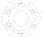
The invention discloses an adjustable wrench, wherein six through holes with pointed circle centers are uniformly distributed on the side wall of a base (7), a screw rod (3) and a moving block (5) for abutting against a bolt head are respectively arranged on the outer side and the inner side of each through hole, an internal thread matched with the screw rod (3) is arranged in the moving block (5), a conical gear I (10) is arranged on the screw rod (3), a circular groove (11) is arranged on the upper surface of the base (7), a driving wheel (8) is arranged on the base (7), a convex ring matched with the circular groove (11) is arranged on the lower end surface of the driving wheel (8), a conical gear II matched with the conical gear I (10) is arranged on the outer side of the convex ring, and a rotary driving bulge (12) is arranged on the upper end surface of the driving wheel (8), the invention can achieve the tightening torque of a fixed-mouth wrench, and one adjustable-mouth wrench can replace fixed-mouth wrenches with, thereby reducing the weight and complexity of the vehicle-mounted tool and simultaneously reducing the purchasing cost for enterprises.
Description
Technical Field
The invention relates to an adjustable wrench, and belongs to the field of maintenance tools.
Background
With the increase of the automobile holding amount in China, the maintenance workload of automobiles is also continuously increased. As is well known, each automobile is equipped with a vehicle-mounted tool when leaving a factory, wherein a wrench is one of the most important vehicle-mounted tools, and because the specifications of parts on the automobile are more, a common shifting wrench cannot meet the requirements of tightening torque, and often needs to be equipped with fixed-mouth wrenches or sleeves of various types, which leads to the weight and complexity of the vehicle-mounted tools.
Namely: the current needs a shifting wrench, which can reach the tightening torque of the fixed-mouth wrench, and one shifting wrench can replace the fixed-mouth wrenches with various specifications, thereby reducing the weight and complexity of the vehicle-mounted tool and simultaneously reducing the purchasing cost for enterprises.
Disclosure of Invention
The invention aims to solve the technical problem of providing an adjustable wrench, which can achieve the tightening torque of a fixed-mouth wrench, and one adjustable wrench can replace fixed-mouth wrenches with various specifications, thereby reducing the weight and complexity of vehicle-mounted tools, reducing the purchasing cost for enterprises and overcoming the defects of the prior art.
The technical scheme of the invention is as follows: the utility model provides an adjustable spanner, it includes the handle, the base of hexagon nut form is installed at the end of handle, lateral wall equipartition at the base is equipped with six directional through-holes in the centre of a circle, install the lead screw respectively and support the motion piece that tight bolt head was used in the outside and the inboard of through-hole, be equipped with in the motion piece with lead screw complex internal thread, be equipped with conical gear I on the lead screw, be equipped with circular recess at the upper surface of base, install the drive wheel on the base, lower terminal surface at the drive wheel is equipped with the bulge loop with circular recess matched with, be equipped with in the outside of bulge loop with I conical gear II that cooperatees of conical gear, it is protruding to be equipped with rotary drive at the.
The handle is composed of a round rod and a cylinder, a hexagonal groove for supporting the outer contour of the base is formed in the middle of the lower end face of the cylinder, a hole for the rotary driving protrusion to penetrate through is formed in the upper end face of the cylinder, a positioning screw hole is formed in the edge of the upper surface of the cylinder, and a positioning screw for fixing the cylinder and the base mutually is installed on the positioning screw hole.
The upper surface of the driving wheel is provided with a first-stage boss matched with the base and a second-stage boss mutually positioned with the handle, and the rotary driving boss is arranged on the second-stage boss.
The through hole is composed of a circular hole in the outer side and a square hole in the inner side, the circular hole is used for installing the screw rod, the square hole is used for installing the square moving block, the outer end of the through hole is provided with the blanking nut, and the inner wall of the outer end of the through hole is provided with an inner thread matched with the blanking nut.
The plug nut is cylindrical, one end of the plug nut is abutted to the bearing, the other end of the plug nut is provided with a hexagonal groove, and the plug nut is externally provided with threads.
And bearings are arranged at the front end and the rear end of the screw rod.
Compared with the prior art, the adjustable wrench is characterized in that six through holes with pointed circle centers are uniformly distributed on the side wall of a base, a screw rod and a moving block for tightly abutting against a bolt head are respectively arranged on the outer side and the inner side of each through hole, an internal thread matched with the screw rod is arranged in each moving block, a conical gear I is arranged on the screw rod, a circular groove is arranged on the upper surface of the base, a driving wheel is arranged on the base, a convex ring matched with the circular groove is arranged on the lower end surface of the driving wheel, a conical gear II matched with the conical gear I is arranged on the outer side of the convex ring, and a rotary driving bulge is arranged on the upper end surface of the driving wheel; one shifting wrench can replace fixed-mouth wrenches with various specifications, so that the weight and complexity of the vehicle-mounted tool are reduced, the purchasing cost of an enterprise is reduced, and meanwhile, the six moving blocks can achieve the tightening torque of the fixed-mouth wrench; the handle is composed of a round rod and a cylinder, a hexagonal groove for supporting the outer contour of the base is arranged in the middle of the lower end face of the cylinder, a rotary driving bulge is arranged on the upper end face of the cylinder and penetrates through the hole, a positioning screw hole is arranged on the edge of the upper surface of the cylinder, and a positioning screw for fixing the cylinder and the base to each other is arranged on the positioning screw hole; the upper surface of the driving wheel is provided with a primary boss matched with the base and a secondary boss for mutual positioning with the handle, and the rotary driving bulge is arranged on the secondary boss, so that the driving wheel can be effectively matched with the base and the handle; the through hole is composed of a circular hole at the outer side and a square hole at the inner side, the circular hole is used for installing a screw rod, the square hole is used for installing a square moving block, a cap nut is installed at the outer end of the through hole, and an internal thread matched with the cap nut is arranged on the inner wall of the outer end of the through hole; the blanking cover nut is the cylinder type, and one end offsets with the bearing, and the other end has hexagonal recess, and the outside has the screw thread, and such structure is screwed up to hexagonal instrument in facilitating the use, makes things convenient for the screw in base.
Drawings
Fig. 1 is a perspective view of the present invention.
Fig. 2 is an exploded view of a novel shifting wrench according to the present invention.
Fig. 3 is a front view of a moving block of the novel shifting wrench nested in a base.
FIG. 4 is a front view of the second bearing, the lead screw, the first bearing and the blind nut of the novel shifting wrench, which are sleeved into the base and sleeved into the base respectively.
Fig. 5 is a front view of the base in which the rest of the motion blocks, the second bearing, the lead screw, the first bearing and the cap nut of the novel shifting wrench are sleeved.
Fig. 6 is a perspective view of the driving wheel of the novel shifting wrench nested in the base.
Fig. 7 is a perspective view of a novel shifting wrench assembly according to the present invention at an angle.
Wherein, the plug cap nut 1; a screw rod 3; a bearing 4; a motion block 5; a set screw 6; a base 7; a drive wheel 8; a handle 9; a bevel gear I10; a circular groove 11; a rotation driving boss 12; a hexagonal recess 13; a secondary boss 14; a circular hole 15; a square hole 16.
Detailed Description
The required components include: the device comprises six plug nuts 1, twelve bearings, six lead screws 3, six moving blocks 5, six positioning screws 6, a base 7, a driving wheel 8 and a handle 9, and is shown in figure 2.
The assembly sequence is as follows: the motion block 5 is sleeved on a square hole 16 in the base 7 from a through hole in the base 7, as shown in figure 3; sequentially sleeving the bearing 4, the screw rod 3, the bearing 4 and the cap nut 1 on a circular hole 15 of the base 7 from the outside of the base 7, wherein the screw rod 3 is screwed into the moving block 5 until the moving block 5 abuts against the base 7, and the cap nut 1 is screwed into the base 7 until the nut 1 abuts against the bearing 4 on the outer side, as shown in fig. 4; repeating the steps, and respectively sleeving the rest five blocking nuts 1, the bearing 4, the screw rod 3 and the motion block 5 into the rest five through holes in the base 7, as shown in fig. 4; the driving wheel 8 is sleeved into the base 7, and the driving wheel 8 is ensured to be meshed with the bevel gear I10 on the screw rod 3, as shown in figure 5; the handle 9 is sleeved into the base 7 to abut against the driving wheel 8, and then the handle 9 and the base 7 are fixed together by six bolts 6 to form a shifting wrench assembly, as shown in fig. 1 and 7.
When the bolt needs to be fastened or loosened, the wrench assembly is sleeved in the bolt head, one hand holds the handle 9, the other hand rotates clockwise to drive the protrusion 12 and simultaneously drives the six screw rods 3 to rotate, the six screw rods 3 respectively drive the six moving blocks 5 until the six moving blocks 5 completely abut against the bolt head, the bolt can be fastened or loosened through the handle 9, and as the moving blocks 5 are driven by the screw rods 3 through threads, the moving blocks 5 cannot reversely drive the screw rods 3, and six faces of the bolt head can be locked in six directions, larger torque can be transmitted.
Claims (3)
1. The utility model provides an adjustable spanner, it includes handle (9), installs base (7) of hexagon nut form, its characterized in that at the end of handle (9): the side wall of the base (7) is uniformly provided with six through holes with directed circle centers, the outer side and the inner side of each through hole are respectively provided with a screw rod (3) and a moving block (5) for abutting against a bolt head, an internal thread matched with the screw rod (3) is arranged in the moving block (5), a conical gear I (10) is arranged on the screw rod (3), the upper surface of the base (7) is provided with a circular groove (11), the base (7) is provided with a driving wheel (8), the lower end surface of the driving wheel (8) is provided with a convex ring matched with the circular groove (11), the outer side of the convex ring is provided with a conical gear II matched with the conical gear I (10), and the upper end surface of the driving wheel (8) is provided with a rotary driving bulge (12); the through hole is composed of a circular hole (15) on the outer side and a square hole (16) on the inner side, the circular hole (15) is used for installing the screw rod (3), the square hole (16) is used for installing the square moving block (5), the outer end of the through hole is provided with the plug nut (1), the inner wall of the outer end of the through hole is provided with an internal thread matched with the plug nut (1), the plug nut (1) is cylindrical, one end of the plug nut is abutted to the bearing (4), the other end of the plug nut is provided with a hexagonal groove, and the outer part of the plug nut is provided with a; the upper surface of the driving wheel (8) is provided with a first-stage boss matched with the base (7) and a second-stage boss (14) mutually positioned with the handle (9), and the rotary driving boss (12) is arranged on the second-stage boss (14).
2. The adjustable wrench as claimed in claim 1, wherein: handle (9) comprise round bar and cylinder, are equipped with hexagon recess (13) that the external profile that supports base (7) was used in the lower terminal surface middle part of cylinder, are equipped with at the up end of cylinder and supply rotary drive arch (12) to alternate the trompil, are equipped with the location screw at the edge of cylinder upper surface, install set screw (6) with cylinder and base (7) reciprocal anchorage usefulness on the location screw.
3. The adjustable wrench as claimed in claim 1, wherein: bearings (4) are arranged at the front end and the rear end of the screw rod (3).
Priority Applications (1)
| Application Number | Priority Date | Filing Date | Title |
|---|---|---|---|
| CN201811257550.6A CN109093548B (en) | 2018-10-26 | 2018-10-26 | Adjustable spanner |
Applications Claiming Priority (1)
| Application Number | Priority Date | Filing Date | Title |
|---|---|---|---|
| CN201811257550.6A CN109093548B (en) | 2018-10-26 | 2018-10-26 | Adjustable spanner |
Publications (2)
| Publication Number | Publication Date |
|---|---|
| CN109093548A CN109093548A (en) | 2018-12-28 |
| CN109093548B true CN109093548B (en) | 2020-12-01 |
Family
ID=64869677
Family Applications (1)
| Application Number | Title | Priority Date | Filing Date |
|---|---|---|---|
| CN201811257550.6A Active CN109093548B (en) | 2018-10-26 | 2018-10-26 | Adjustable spanner |
Country Status (1)
| Country | Link |
|---|---|
| CN (1) | CN109093548B (en) |
Families Citing this family (2)
| Publication number | Priority date | Publication date | Assignee | Title |
|---|---|---|---|---|
| CN113400231B (en) * | 2021-02-02 | 2023-06-09 | 张勇 | Multifunctional automatic wrench for petrochemical equipment and use method thereof |
| CN113370126A (en) * | 2021-05-29 | 2021-09-10 | 马斯特科技(武汉)有限公司 | Electric automatic nut adjusting device |
Citations (4)
| Publication number | Priority date | Publication date | Assignee | Title |
|---|---|---|---|---|
| KR20150085545A (en) * | 2014-01-15 | 2015-07-24 | 김청준 | Free size wrench |
| CN106392961A (en) * | 2016-11-11 | 2017-02-15 | 苏州创必成电子科技有限公司 | Movable wrench allowing caliber to be conveniently adjusted |
| CN107838725A (en) * | 2017-12-18 | 2018-03-27 | 吉林大学 | One kind measures adjustable multiple parabolic mirrors clamp for machining simultaneously off axis |
| CN207788765U (en) * | 2018-01-23 | 2018-08-31 | 东莞市诺泰五金制品有限公司 | A metal socket wrench tool |
-
2018
- 2018-10-26 CN CN201811257550.6A patent/CN109093548B/en active Active
Patent Citations (4)
| Publication number | Priority date | Publication date | Assignee | Title |
|---|---|---|---|---|
| KR20150085545A (en) * | 2014-01-15 | 2015-07-24 | 김청준 | Free size wrench |
| CN106392961A (en) * | 2016-11-11 | 2017-02-15 | 苏州创必成电子科技有限公司 | Movable wrench allowing caliber to be conveniently adjusted |
| CN107838725A (en) * | 2017-12-18 | 2018-03-27 | 吉林大学 | One kind measures adjustable multiple parabolic mirrors clamp for machining simultaneously off axis |
| CN207788765U (en) * | 2018-01-23 | 2018-08-31 | 东莞市诺泰五金制品有限公司 | A metal socket wrench tool |
Also Published As
| Publication number | Publication date |
|---|---|
| CN109093548A (en) | 2018-12-28 |
Similar Documents
| Publication | Publication Date | Title |
|---|---|---|
| CN206185811U (en) | Multiaxis linkage standard component pretension frock | |
| CN111843896B (en) | Adjustable inner hexagonal socket wrench | |
| CN213259192U (en) | Screw dismounting tool for mounting high-low voltage power supply and distribution system | |
| CN110219875B (en) | Hexagon socket head cap screw fastener | |
| CN109093548A (en) | A kind of monkey wrench | |
| CN111618771A (en) | Tool for assembling and disassembling bolt in narrow space and using method thereof | |
| CN1517565A (en) | Nuts, fasteners with nuts and fastening devices thereof | |
| CN212763222U (en) | Be used for quick pretension and accurate torsion control synchronizer | |
| CN211163731U (en) | Universal sleeve with self-sealing washer positioning | |
| CN218856090U (en) | Bearing installation and cap locking device | |
| CN108858011B (en) | Tightening device and method for cable sealing external member in narrow space of box body | |
| CN111152152A (en) | A spanner for narrow space | |
| CN220051628U (en) | Spanner extender capable of entering narrow space | |
| CN215548370U (en) | Screwing and fastening device for narrow space | |
| CN218698232U (en) | Bolt screwing and locking device | |
| CN221436339U (en) | Wheel claw nut tensioning device | |
| CN219649753U (en) | Bidirectional ratchet wrench | |
| CN217833459U (en) | A kind of spanner | |
| CN211805812U (en) | A spanner for narrow space | |
| CN212763214U (en) | Fastening power assisting device capable of supporting complex conditions | |
| CN101927471B (en) | Sleeve tool for wrenching bolt | |
| CN112264955A (en) | A limit moment of torsion autowrench for aeroengine assembly | |
| CN204935485U (en) | A kind of connector spanner | |
| CN220227442U (en) | Inner hexagon screw fastener | |
| CN221696719U (en) | A sprocket transmission adjusting wrench |
Legal Events
| Date | Code | Title | Description |
|---|---|---|---|
| PB01 | Publication | ||
| PB01 | Publication | ||
| SE01 | Entry into force of request for substantive examination | ||
| SE01 | Entry into force of request for substantive examination | ||
| GR01 | Patent grant | ||
| GR01 | Patent grant |