CN109044687B - Arm support frame for surgical arm-injured patient - Google Patents
Arm support frame for surgical arm-injured patient Download PDFInfo
- Publication number
- CN109044687B CN109044687B CN201810776330.8A CN201810776330A CN109044687B CN 109044687 B CN109044687 B CN 109044687B CN 201810776330 A CN201810776330 A CN 201810776330A CN 109044687 B CN109044687 B CN 109044687B
- Authority
- CN
- China
- Prior art keywords
- shaped frame
- spring
- hole
- frame
- arm
- Prior art date
- Legal status (The legal status is an assumption and is not a legal conclusion. Google has not performed a legal analysis and makes no representation as to the accuracy of the status listed.)
- Expired - Fee Related
Links
Images


Classifications
-
- A—HUMAN NECESSITIES
- A61—MEDICAL OR VETERINARY SCIENCE; HYGIENE
- A61G—TRANSPORT, PERSONAL CONVEYANCES OR ACCOMMODATION SPECIALLY ADAPTED FOR PATIENTS OR DISABLED PERSONS; OPERATING TABLES OR CHAIRS; CHAIRS FOR DENTISTRY; FUNERAL DEVICES
- A61G12/00—Accommodation for nursing, e.g. in hospitals, not covered by groups A61G1/00 - A61G11/00, e.g. trolleys for transport of medicaments or food; Prescription lists
Landscapes
- Health & Medical Sciences (AREA)
- Nursing (AREA)
- Life Sciences & Earth Sciences (AREA)
- Animal Behavior & Ethology (AREA)
- General Health & Medical Sciences (AREA)
- Public Health (AREA)
- Veterinary Medicine (AREA)
- Invalid Beds And Related Equipment (AREA)
Abstract
本发明涉及一种外科用支撑架,尤其涉及一种外科用手臂受伤病人手臂支撑架。要解决的技术问题是:提供一种能够托住病人手臂,防止病人的手臂摆动的外科用手臂受伤病人手臂支撑架。一种外科用手臂受伤病人手臂支撑架,包括有底座、第一N型架、第一滑轨、第一滑块、第二N型架、电机、第一轴承座、螺杆等;底座的顶部连接有第一N型架,第一N型架的内左壁嵌入式设有第一滑轨,第一滑轨上滑动式设有第一滑块。本发明通过电机转动,电机带动螺杆转动,螺杆与螺纹孔配合,从而带动第二N型架向上或者向下移动,用以调节U型架及其上部件的高度,以适应病人的高度,并且还利用护垫来保护病人的手臂,同时也使手臂舒适的放在护垫上,减轻疼痛感。
The invention relates to a surgical support frame, in particular to an arm support frame for a surgically injured patient. The technical problem to be solved is to provide a surgical arm support frame for the injured patient, which can hold the patient's arm and prevent the patient's arm from swinging. An arm support frame for a surgically injured patient includes a base, a first N-shaped frame, a first slide rail, a first slider, a second N-shaped frame, a motor, a first bearing seat, a screw rod, and the like; A first N-shaped frame is connected, the inner left wall of the first N-shaped frame is embedded with a first sliding rail, and a first sliding block is slidably arranged on the first sliding rail. In the present invention, the motor rotates, the motor drives the screw to rotate, and the screw is matched with the threaded hole, thereby driving the second N-shaped frame to move up or down, so as to adjust the height of the U-shaped frame and its upper parts to adapt to the height of the patient, and A pad is also used to protect the patient's arm, while also allowing the arm to rest comfortably on the pad to reduce pain.
Description
技术领域technical field
本发明涉及一种外科用支撑架,尤其涉及一种外科用手臂受伤病人手臂支撑架。The invention relates to a surgical support frame, in particular to an arm support frame for a surgically injured patient.
背景技术Background technique
外科是研究外科疾病的发生,发展规律及其临床表现,诊断,预防和治疗的科学,是以手术切除、修补为主要治病手段的专业科室。Surgery is a science that studies the occurrence, development and clinical manifestations, diagnosis, prevention and treatment of surgical diseases.
在很多事故中,常常有人的手臂或擦伤或皮肉绽开,送至医院后总是需要医生为病人们擦药、缝针,一般总是病人将手臂抬起,但抬起的时间长了,病人的手臂会感觉酸痛,加重手臂疼痛感,且可能左右摆动,不方便医生操作。In many accidents, people's arms are often bruised or their flesh is split open. After being sent to the hospital, the doctor always needs to apply medicine and stitches to the patients. Generally, the patient always lifts the arm, but it takes a long time to lift. The patient's arm will feel sore, aggravating the pain in the arm, and may swing left and right, which is inconvenient for the doctor to operate.
发明内容SUMMARY OF THE INVENTION
为了克服手臂受伤病人在将其手臂抬起时会有酸痛感,加重手臂疼痛感,还可能在医生检查其手臂时支撑不住而左右摆动的缺点,要解决的技术问题是:提供一种能够托住病人手臂,防止病人的手臂摆动的外科用手臂受伤病人手臂支撑架。In order to overcome the disadvantage that patients with arm injuries will feel sore when they lift their arms, aggravate the pain of the arms, and may not be able to support their arms and swing left and right when the doctor examines their arms, the technical problem to be solved is: to provide a technology that can A surgical arm that holds the patient's arm and prevents the patient's arm from swinging. Patient arm support.
一种外科用手臂受伤病人手臂支撑架,包括有底座、第一N型架、第一滑轨、第一滑块、第二N型架、电机、第一轴承座、螺杆、U型架、第二滑块、第二滑轨、第三N型架、连杆、第一连接块、第二轴承座、弧形压板、第一管套、顶杆和第一弹簧,底座的顶部连接有第一N型架,第一N型架的内左壁嵌入式设有第一滑轨,第一滑轨上滑动式设有第一滑块,第一N型架的顶部左右对称开有第一通孔,第一滑块的右侧面连接有第二N型架,第二N型架的左右两壁上部穿过第一通孔,第二N型架的底部开有螺纹孔,底座的顶部左侧设有电机,电机位于第一N型架的内部,第一N型架的内顶部左侧嵌入式设有第一轴承座,第一轴承座位于左右两个第一通孔之间,第一轴承座内连接有螺杆,螺杆穿过螺纹孔,且螺杆下端与电机连接,第二N型架的顶部连接有U型架,U型架的上部前后对称连接有第二滑块,第二滑块连接有第二滑轨,两个第二滑轨连接有第三N型架,第二滑轨位于第三N型架的内侧下部,第三N型架的顶部中间开有第二通孔,第二通孔内设有连杆,连杆的顶端连接有第一连接块,连杆的底部连接有第二轴承座,第二轴承座上连接有弧形压板,U型架的底部左右两侧设有第一管套,第一管套的内顶部连接有第一弹簧,第一弹簧的底端连接有顶杆,顶杆与第一N型架的顶部接触。An arm support frame for a patient with a surgical arm injury, comprising a base, a first N-shaped frame, a first slide rail, a first sliding block, a second N-shaped frame, a motor, a first bearing seat, a screw rod, a U-shaped frame, The second sliding block, the second sliding rail, the third N-shaped frame, the connecting rod, the first connecting block, the second bearing seat, the arc pressure plate, the first tube sleeve, the ejector rod and the first spring, the top of the base is connected with a The first N-shaped frame, the inner left wall of the first N-shaped frame is embedded with a first sliding rail, the first sliding rail is slidably provided with a first sliding block, and the top of the first N-shaped frame is symmetrical with A through hole, a second N-shaped frame is connected to the right side of the first slider, the upper part of the left and right walls of the second N-shaped frame passes through the first through hole, the bottom of the second N-shaped frame is provided with a threaded hole, and the base There is a motor on the left side of the top of the first N-type frame. The motor is located inside the first N-type frame. The inner top left side of the first N-type frame is embedded with a first bearing seat, and the first bearing seat is located between the left and right first through holes. The first bearing seat is connected with a screw rod, the screw rod passes through the threaded hole, and the lower end of the screw rod is connected with the motor, the top of the second N-shaped frame is connected with a U-shaped frame, and the upper part of the U-shaped frame is symmetrically connected with a second slider. , the second sliding block is connected with a second sliding rail, the two second sliding rails are connected with a third N-shaped frame, the second sliding rail is located at the inner lower part of the third N-shaped frame, and the middle of the top of the third N-shaped frame is opened with The second through hole is provided with a connecting rod, the top of the connecting rod is connected with a first connecting block, the bottom of the connecting rod is connected with a second bearing seat, and the second bearing seat is connected with an arc pressure plate, U-shaped The bottom, left and right sides of the frame are provided with first tube sleeves, the inner top of the first tube sleeve is connected with a first spring, and the bottom end of the first spring is connected with an ejector rod, and the ejector rod is in contact with the top of the first N-shaped frame.
此外,特别优选的是,还包括有第一挂钩、转杆、第二连接块、第二弹簧、框体、第三弹簧、第三滑块和第二挂钩,第二N型架的右壁上部设有第一挂钩,第一N型架的右壁上部开有第三通孔,第三通孔内设有框体,第三通孔的右壁内侧上部水平连接有转杆,转杆位于第三通孔下方,框体的左侧底部连接有第二连接块,第二连接块上开有第四通孔,转杆穿过第四通孔,第二连接块的右侧面与第一N型架的内右壁之间连接有第二弹簧,第二弹簧处于拉伸状态,第二弹簧缠绕在转杆上,框体的左壁下部开有第一滑槽,第一滑槽的内滑动式设有第三滑块,第三滑块与第一滑槽的底部之间连接有第三弹簧,第三滑块的左侧面连接有第二挂钩,第二挂钩位于第一挂钩下方,且第二挂钩与第一挂钩相挂接触。In addition, it is particularly preferable to further include a first hook, a rotating rod, a second connecting block, a second spring, a frame, a third spring, a third slider and a second hook, and the right wall of the second N-shaped frame The upper part is provided with a first hook, the upper part of the right wall of the first N-shaped frame is provided with a third through hole, a frame body is arranged in the third through hole, and a rotating rod is horizontally connected to the upper part of the inner side of the right wall of the third through hole. Below the third through hole, a second connecting block is connected to the bottom left side of the frame body, a fourth through hole is opened on the second connecting block, the rotating rod passes through the fourth through hole, and the right side of the second connecting block is connected to the fourth through hole. A second spring is connected between the inner right wall of the first N-type frame, the second spring is in a stretched state, the second spring is wound on the rotating rod, and the lower part of the left wall of the frame is provided with a first chute, the first sliding A third sliding block is arranged inside the groove, a third spring is connected between the third sliding block and the bottom of the first sliding groove, and a second hook is connected to the left side of the third sliding block, and the second hook is located on the first sliding block. Below a hook, and the second hook is in hanging contact with the first hook.
此外,特别优选的是,还包括有第二管套、第四弹簧和滑轮,第一N型架的内顶部右侧开有第二滑槽,框体的左壁顶部连接有第二管套,第二管套的内底部连接有第四弹簧,第四弹簧的顶端连接有滑轮,滑轮位于第二滑槽内。In addition, it is particularly preferred that a second sleeve, a fourth spring and a pulley are also included, a second chute is opened on the right side of the inner top of the first N-shaped frame, and a second sleeve is connected to the top of the left wall of the frame. , the inner bottom of the second sleeve is connected with a fourth spring, the top of the fourth spring is connected with a pulley, and the pulley is located in the second chute.
此外,特别优选的是,还包括有第三管套、第五弹簧、连接杆和护垫,U型架的内顶部开有凹槽,凹槽内间隔均匀的连接有多个第三管套,第三管套的内底部连接有第五弹簧,第五弹簧的顶端连接有连接杆,连接杆的顶端连接有护垫。In addition, it is particularly preferred that a third tube sleeve, a fifth spring, a connecting rod and a protective pad are also included, a groove is formed on the inner top of the U-shaped frame, and a plurality of third tube sleeves are connected with uniform intervals in the groove. The inner bottom of the third sleeve is connected with a fifth spring, the top of the fifth spring is connected with a connecting rod, and the top of the connecting rod is connected with a protective pad.
当病人的手臂需要伸出来给医生擦药或者缝针时,医生先控制电机顺时针或逆时针转动,电机转动通过螺杆和螺纹孔的配合,使第二N型架向上或向下移动,当第二N型架向下移动时,顶杆与第一N型架的顶部接触,第一弹簧起缓冲作用,如此能够调节U型架的高度,调节好高度后,关闭电机。医生向上拉第一连接块,第一连接块上移动连杆也向上移动,然后病人将手臂放在U型架内,再放开第一连接块,使弧形压板压住手臂,然后医生开始为病人的手臂擦药或者缝针。当擦药或者缝针完成之后,向上拉第一连接块使弧形压板与手臂不接触,然后将手臂拿出来即可。When the patient's arm needs to be stretched out to give the doctor medicine or stitches, the doctor first controls the motor to rotate clockwise or counterclockwise, and the motor rotates through the cooperation of the screw and the threaded hole, so that the second N-shaped frame moves up or down. When the second N-shaped frame moves downward, the top rod contacts the top of the first N-shaped frame, and the first spring acts as a buffer, so that the height of the U-shaped frame can be adjusted. After the height is adjusted, the motor is turned off. The doctor pulls the first connecting block upward, and the moving link on the first connecting block also moves upward, then the patient puts the arm in the U-shaped frame, and then releases the first connecting block, so that the arc pressure plate presses the arm, and then the doctor starts Apply medicine or stitches to the patient's arm. After wiping the medicine or stitching the needle, pull up the first connecting block so that the arc pressure plate does not contact the arm, and then take the arm out.
当第二N型架向上移动时,第二挂钩与第一挂钩不接触,如此框体能够在第二弹簧的弹力作用下向右移动,然后将擦药或者缝针需要用的药品和物件放入框体内。使用完成后再将框体推回,然后启动电机顺时针转动,电机顺时针转动带动螺杆转动,螺杆转动使第二N型架向下移动,第二N型架向下移动使第一挂钩挂住第二挂钩,当第一挂钩挂在第二挂钩上后关闭电机。如此方便医生在工作时方便拿所需之物。When the second N-shaped frame moves upward, the second hook does not contact the first hook, so that the frame body can move to the right under the elastic force of the second spring, and then put the medicines and objects needed for wiping medicine or sewing needles. into the frame. After use, push the frame back, then start the motor to rotate clockwise, the motor rotates clockwise to drive the screw to rotate, the screw rotates to move the second N-shaped frame downward, and the second N-shaped frame moves downward to make the first hook hang. Hold the second hook and turn off the motor when the first hook is hung on the second hook. This makes it easy for doctors to get what they need while they work.
框体向右移动或向左移动时,滑轮在第二滑槽内滑动,防止框体左右移动时磨损。When the frame body moves to the right or left, the pulley slides in the second chute to prevent the frame body from being worn when it moves left and right.
手臂放入U型架内时,手臂放在护垫上,由于手臂有重量,能够使护垫向下移动,并压缩第五弹簧,起缓冲作用。当医生擦完药或者缝完针后,病人的手臂拿开,护垫在第五弹簧的弹力作用下复位。如此能够使病人的手臂放的更舒服。When the arm is put into the U-shaped frame, the arm is placed on the pad. Due to the weight of the arm, the pad can be moved downward, and the fifth spring can be compressed to play a buffering role. After the doctor wipes the medicine or sews the needle, the patient's arm is removed, and the pad is reset under the elastic force of the fifth spring. This can make the patient's arm more comfortable.
本发明的有益效果:本发明通过电机转动,电机带动螺杆转动,螺杆与螺纹孔配合,从而带动第二N型架向上或者向下移动,用以调节U型架及其上部件的高度,以适应病人的高度,并且还利用护垫来保护病人的手臂,同时也使手臂舒适的放在护垫上,减轻疼痛感。Beneficial effects of the present invention: the present invention rotates the motor, the motor drives the screw to rotate, and the screw is matched with the threaded hole, thereby driving the second N-shaped frame to move up or down, so as to adjust the height of the U-shaped frame and its upper parts, so as to adjust the height of the U-shaped frame and its upper parts. Adapt to the height of the patient, and also use the pad to protect the patient's arm, while also making the arm rest on the pad comfortably, reducing pain.
附图说明Description of drawings
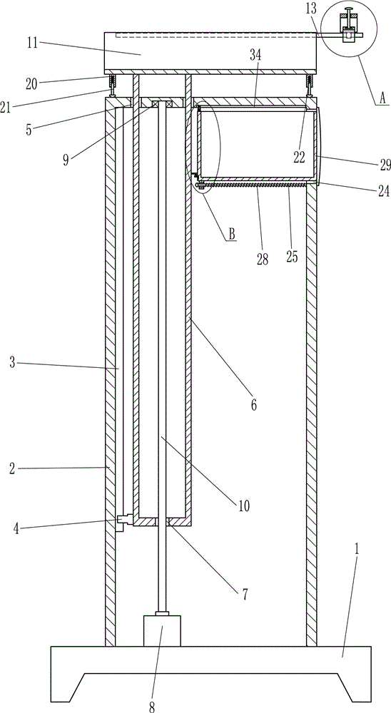
图1为本发明的主视结构示意图。FIG. 1 is a schematic view of the front structure of the present invention.
图2为本发明A部分的放大示意图。Figure 2 is an enlarged schematic view of Part A of the present invention.
图3为本发明B部分的放大示意图。Figure 3 is an enlarged schematic view of part B of the present invention.
图4为本发明的部分左视结构示意图。FIG. 4 is a partial left-view structural schematic diagram of the present invention.
图中标号名称:1底座,2第一N型架,3第一滑轨,4第一滑块,5第一通孔,6第二N型架,7螺纹孔,8电机,9第一轴承座,10螺杆,11U型架,12第二滑块,13第二滑轨,14第三N型架,15第二通孔,16连杆,17第一连接块,18第二轴承座,19弧形压板,20第一管套,21顶杆,22第一弹簧,23第一挂钩,24第三通孔,25转杆,26第二连接块,27第四通孔,28第二弹簧,29框体,30第一滑槽,31第三弹簧,32第三滑块,33第二挂钩,34第二滑槽,35第二管套,36第四弹簧,37滑轮,38凹槽,39第三管套,40第五弹簧,41连接杆,42护垫。Label name in the figure: 1 base, 2 first N frame, 3 first slide rail, 4 first slider, 5 first through hole, 6 second N frame, 7 threaded hole, 8 motor, 9 first Bearing seat, 10 screw, 11 U-shaped frame, 12 second slider, 13 second slide rail, 14 third N-shaped frame, 15 second through hole, 16 connecting rod, 17 first connecting block, 18 second bearing seat , 19 arc pressure plate, 20 first sleeve, 21 ejector rod, 22 first spring, 23 first hook, 24 third through hole, 25 rotating rod, 26 second connecting block, 27 fourth through hole, 28 first 2 springs, 29 frame, 30 first chute, 31 third spring, 32 third slider, 33 second hook, 34 second chute, 35 second sleeve, 36 fourth spring, 37 pulley, 38 groove, 39 third sleeve, 40 fifth spring, 41 connecting rod, 42 pad.
具体实施方式Detailed ways
为使本发明的目的、技术方案和优点更加清楚明了,下面结合具体实施方式并参照附图,对本发明进一步详细说明。应该理解,这些描述只是示例性的,而并非要限制本发明的范围。此外,在以下说明中,省略了对公知结构和技术的描述,以避免不必要地混淆本发明的概念。In order to make the objectives, technical solutions and advantages of the present invention clearer, the present invention will be further described in detail below with reference to the specific embodiments and the accompanying drawings. It should be understood that these descriptions are exemplary only and are not intended to limit the scope of the invention. Also, in the following description, descriptions of well-known structures and techniques are omitted to avoid unnecessarily obscuring the concepts of the present invention.
实施例1Example 1
一种外科用手臂受伤病人手臂支撑架,如图1-4所示,包括有底座1、第一N型架2、第一滑轨3、第一滑块4、第二N型架6、电机8、第一轴承座9、螺杆10、U型架11、第二滑块12、第二滑轨13、第三N型架14、连杆16、第一连接块17、第二轴承座18、弧形压板19、第一管套20、顶杆21和第一弹簧22,底座1的顶部连接有第一N型架2,第一N型架2的内左壁嵌入式设有第一滑轨3,第一滑轨3上滑动式设有第一滑块4,第一N型架2的顶部左右对称开有第一通孔5,第一滑块4的右侧面连接有第二N型架6,第二N型架6的左右两壁上部穿过第一通孔5,第二N型架6的底部开有螺纹孔7,底座1的顶部左侧设有电机8,电机8位于第一N型架2的内部,第一N型架2的内顶部左侧嵌入式设有第一轴承座9,第一轴承座9位于左右两个第一通孔5之间,第一轴承座9内连接有螺杆10,螺杆10穿过螺纹孔7,且螺杆10下端与电机8连接,第二N型架6的顶部连接有U型架11,U型架11的上部前后对称连接有第二滑块12,第二滑块12连接有第二滑轨13,两个第二滑轨13连接有第三N型架14,第二滑轨13位于第三N型架14的内侧下部,第三N型架14的顶部中间开有第二通孔15,第二通孔15内设有连杆16,连杆16的顶端连接有第一连接块17,连杆16的底部连接有第二轴承座18,第二轴承座18上连接有弧形压板19,U型架11的底部左右两侧设有第一管套20,第一管套20的内顶部连接有第一弹簧22,第一弹簧22的底端连接有顶杆21,顶杆21与第一N型架2的顶部接触。An arm support frame for a patient with a surgical arm injury, as shown in Figures 1-4, includes a base 1, a first N-
实施例2Example 2
一种外科用手臂受伤病人手臂支撑架,如图1-4所示,包括有底座1、第一N型架2、第一滑轨3、第一滑块4、第二N型架6、电机8、第一轴承座9、螺杆10、U型架11、第二滑块12、第二滑轨13、第三N型架14、连杆16、第一连接块17、第二轴承座18、弧形压板19、第一管套20、顶杆21和第一弹簧22,底座1的顶部连接有第一N型架2,第一N型架2的内左壁嵌入式设有第一滑轨3,第一滑轨3上滑动式设有第一滑块4,第一N型架2的顶部左右对称开有第一通孔5,第一滑块4的右侧面连接有第二N型架6,第二N型架6的左右两壁上部穿过第一通孔5,第二N型架6的底部开有螺纹孔7,底座1的顶部左侧设有电机8,电机8位于第一N型架2的内部,第一N型架2的内顶部左侧嵌入式设有第一轴承座9,第一轴承座9位于左右两个第一通孔5之间,第一轴承座9内连接有螺杆10,螺杆10穿过螺纹孔7,且螺杆10下端与电机8连接,第二N型架6的顶部连接有U型架11,U型架11的上部前后对称连接有第二滑块12,第二滑块12连接有第二滑轨13,两个第二滑轨13连接有第三N型架14,第二滑轨13位于第三N型架14的内侧下部,第三N型架14的顶部中间开有第二通孔15,第二通孔15内设有连杆16,连杆16的顶端连接有第一连接块17,连杆16的底部连接有第二轴承座18,第二轴承座18上连接有弧形压板19,U型架11的底部左右两侧设有第一管套20,第一管套20的内顶部连接有第一弹簧22,第一弹簧22的底端连接有顶杆21,顶杆21与第一N型架2的顶部接触。An arm support frame for a patient with a surgical arm injury, as shown in Figures 1-4, includes a base 1, a first N-
还包括有第一挂钩23、转杆25、第二连接块26、第二弹簧28、框体29、第三弹簧31、第三滑块32和第二挂钩33,第二N型架6的右壁上部设有第一挂钩23,第一N型架2的右壁上部开有第三通孔24,第三通孔24内设有框体29,第三通孔24的右壁内侧上部水平连接有转杆25,转杆25位于第三通孔24下方,框体29的左侧底部连接有第二连接块26,第二连接块26上开有第四通孔27,转杆25穿过第四通孔27,第二连接块26的右侧面与第一N型架2的内右壁之间连接有第二弹簧28,第二弹簧28处于拉伸状态,第二弹簧28缠绕在转杆25上,框体29的左壁下部开有第一滑槽30,第一滑槽30的内滑动式设有第三滑块32,第三滑块32与第一滑槽30的底部之间连接有第三弹簧31,第三滑块32的左侧面连接有第二挂钩33,第二挂钩33位于第一挂钩23下方,且第二挂钩33与第一挂钩23相挂接触。It also includes a
实施例3Example 3
一种外科用手臂受伤病人手臂支撑架,如图1-4所示,包括有底座1、第一N型架2、第一滑轨3、第一滑块4、第二N型架6、电机8、第一轴承座9、螺杆10、U型架11、第二滑块12、第二滑轨13、第三N型架14、连杆16、第一连接块17、第二轴承座18、弧形压板19、第一管套20、顶杆21和第一弹簧22,底座1的顶部连接有第一N型架2,第一N型架2的内左壁嵌入式设有第一滑轨3,第一滑轨3上滑动式设有第一滑块4,第一N型架2的顶部左右对称开有第一通孔5,第一滑块4的右侧面连接有第二N型架6,第二N型架6的左右两壁上部穿过第一通孔5,第二N型架6的底部开有螺纹孔7,底座1的顶部左侧设有电机8,电机8位于第一N型架2的内部,第一N型架2的内顶部左侧嵌入式设有第一轴承座9,第一轴承座9位于左右两个第一通孔5之间,第一轴承座9内连接有螺杆10,螺杆10穿过螺纹孔7,且螺杆10下端与电机8连接,第二N型架6的顶部连接有U型架11,U型架11的上部前后对称连接有第二滑块12,第二滑块12连接有第二滑轨13,两个第二滑轨13连接有第三N型架14,第二滑轨13位于第三N型架14的内侧下部,第三N型架14的顶部中间开有第二通孔15,第二通孔15内设有连杆16,连杆16的顶端连接有第一连接块17,连杆16的底部连接有第二轴承座18,第二轴承座18上连接有弧形压板19,U型架11的底部左右两侧设有第一管套20,第一管套20的内顶部连接有第一弹簧22,第一弹簧22的底端连接有顶杆21,顶杆21与第一N型架2的顶部接触。An arm support frame for a patient with a surgical arm injury, as shown in Figures 1-4, includes a base 1, a first N-shaped
还包括有第一挂钩23、转杆25、第二连接块26、第二弹簧28、框体29、第三弹簧31、第三滑块32和第二挂钩33,第二N型架6的右壁上部设有第一挂钩23,第一N型架2的右壁上部开有第三通孔24,第三通孔24内设有框体29,第三通孔24的右壁内侧上部水平连接有转杆25,转杆25位于第三通孔24下方,框体29的左侧底部连接有第二连接块26,第二连接块26上开有第四通孔27,转杆25穿过第四通孔27,第二连接块26的右侧面与第一N型架2的内右壁之间连接有第二弹簧28,第二弹簧28处于拉伸状态,第二弹簧28缠绕在转杆25上,框体29的左壁下部开有第一滑槽30,第一滑槽30的内滑动式设有第三滑块32,第三滑块32与第一滑槽30的底部之间连接有第三弹簧31,第三滑块32的左侧面连接有第二挂钩33,第二挂钩33位于第一挂钩23下方,且第二挂钩33与第一挂钩23相挂接触。It also includes a
还包括有第二管套35、第四弹簧36和滑轮37,第一N型架2的内顶部右侧开有第二滑槽34,框体29的左壁顶部连接有第二管套35,第二管套35的内底部连接有第四弹簧36,第四弹簧36的顶端连接有滑轮37,滑轮37位于第二滑槽34内。It also includes a
实施例4Example 4
一种外科用手臂受伤病人手臂支撑架,如图1-4所示,包括有底座1、第一N型架2、第一滑轨3、第一滑块4、第二N型架6、电机8、第一轴承座9、螺杆10、U型架11、第二滑块12、第二滑轨13、第三N型架14、连杆16、第一连接块17、第二轴承座18、弧形压板19、第一管套20、顶杆21和第一弹簧22,底座1的顶部连接有第一N型架2,第一N型架2的内左壁嵌入式设有第一滑轨3,第一滑轨3上滑动式设有第一滑块4,第一N型架2的顶部左右对称开有第一通孔5,第一滑块4的右侧面连接有第二N型架6,第二N型架6的左右两壁上部穿过第一通孔5,第二N型架6的底部开有螺纹孔7,底座1的顶部左侧设有电机8,电机8位于第一N型架2的内部,第一N型架2的内顶部左侧嵌入式设有第一轴承座9,第一轴承座9位于左右两个第一通孔5之间,第一轴承座9内连接有螺杆10,螺杆10穿过螺纹孔7,且螺杆10下端与电机8连接,第二N型架6的顶部连接有U型架11,U型架11的上部前后对称连接有第二滑块12,第二滑块12连接有第二滑轨13,两个第二滑轨13连接有第三N型架14,第二滑轨13位于第三N型架14的内侧下部,第三N型架14的顶部中间开有第二通孔15,第二通孔15内设有连杆16,连杆16的顶端连接有第一连接块17,连杆16的底部连接有第二轴承座18,第二轴承座18上连接有弧形压板19,U型架11的底部左右两侧设有第一管套20,第一管套20的内顶部连接有第一弹簧22,第一弹簧22的底端连接有顶杆21,顶杆21与第一N型架2的顶部接触。An arm support frame for a patient with a surgical arm injury, as shown in Figures 1-4, includes a base 1, a first N-shaped
还包括有第一挂钩23、转杆25、第二连接块26、第二弹簧28、框体29、第三弹簧31、第三滑块32和第二挂钩33,第二N型架6的右壁上部设有第一挂钩23,第一N型架2的右壁上部开有第三通孔24,第三通孔24内设有框体29,第三通孔24的右壁内侧上部水平连接有转杆25,转杆25位于第三通孔24下方,框体29的左侧底部连接有第二连接块26,第二连接块26上开有第四通孔27,转杆25穿过第四通孔27,第二连接块26的右侧面与第一N型架2的内右壁之间连接有第二弹簧28,第二弹簧28处于拉伸状态,第二弹簧28缠绕在转杆25上,框体29的左壁下部开有第一滑槽30,第一滑槽30的内滑动式设有第三滑块32,第三滑块32与第一滑槽30的底部之间连接有第三弹簧31,第三滑块32的左侧面连接有第二挂钩33,第二挂钩33位于第一挂钩23下方,且第二挂钩33与第一挂钩23相挂接触。It also includes a
还包括有第二管套35、第四弹簧36和滑轮37,第一N型架2的内顶部右侧开有第二滑槽34,框体29的左壁顶部连接有第二管套35,第二管套35的内底部连接有第四弹簧36,第四弹簧36的顶端连接有滑轮37,滑轮37位于第二滑槽34内。It also includes a
还包括有第三管套39、第五弹簧40、连接杆41和护垫42,U型架11的内顶部开有凹槽38,凹槽38内间隔均匀的连接有多个第三管套39,第三管套39的内底部连接有第五弹簧40,第五弹簧40的顶端连接有连接杆41,连接杆41的顶端连接有护垫42。It also includes a
当病人的手臂需要伸出来给医生擦药或者缝针时,医生先控制电机8顺时针或逆时针转动,电机8转动通过螺杆10和螺纹孔7的配合,使第二N型架6向上或向下移动,当第二N型架6向下移动时,顶杆21与第一N型架2的顶部接触,第一弹簧22起缓冲作用,如此能够调节U型架11的高度,调节好高度后,关闭电机8。医生向上拉第一连接块17,第一连接块17上移动连杆16也向上移动,然后病人将手臂放在U型架11内,再放开第一连接块17,使弧形压板19压住手臂,然后医生开始为病人的手臂擦药或者缝针。当擦药或者缝针完成之后,向上拉第一连接块17使弧形压板19与手臂不接触,然后将手臂拿出来即可。When the patient's arm needs to be stretched out to give the doctor medicine or stitches, the doctor first controls the motor 8 to rotate clockwise or counterclockwise, and the motor 8 rotates through the cooperation of the screw 10 and the threaded hole 7, so that the second N-shaped
当第二N型架6向上移动时,第二挂钩33与第一挂钩23不接触,如此框体29能够在第二弹簧28的弹力作用下向右移动,然后将擦药或者缝针需要用的药品和物件放入框体29内。使用完成后再将框体29推回,然后启动电机8顺时针转动,电机8顺时针转动带动螺杆10转动,螺杆10转动使第二N型架6向下移动,第二N型架6向下移动使第一挂钩23挂住第二挂钩33,当第一挂钩23挂在第二挂钩33上后关闭电机8。如此方便医生在工作时方便拿所需之物。When the second N-shaped
框体29向右移动或向左移动时,滑轮37在第二滑槽34内滑动,防止框体29左右移动时磨损。When the
手臂放入U型架11内时,手臂放在护垫42上,由于手臂有重量,能够使护垫42向下移动,并压缩第五弹簧40,起缓冲作用。当医生擦完药或者缝完针后,病人的手臂拿开,护垫42在第五弹簧40的弹力作用下复位。如此能够使病人的手臂放的更舒服。When the arm is put into the
以上对本申请进行了详细介绍,本文中应用了具体个例对本申请的原理及实施方式进行了阐述,以上实施例的说明只是用于帮助理解本申请的方法及其核心思想;同时,对于本领域的一般技术人员,依据本申请的思想,在具体实施方式及应用范围上均会有改变之处,综上所述,本说明书内容不应理解为对本申请的限制。The application has been introduced in detail above, and specific examples are used to illustrate the principles and implementations of the application. The descriptions of the above embodiments are only used to help understand the methods and core ideas of the application; According to the idea of the present application, there will be changes in the specific embodiments and application scope for those skilled in the art. To sum up, the content of this specification should not be construed as a limitation on the present application.
Claims (3)
Priority Applications (1)
| Application Number | Priority Date | Filing Date | Title |
|---|---|---|---|
| CN201810776330.8A CN109044687B (en) | 2018-07-16 | 2018-07-16 | Arm support frame for surgical arm-injured patient |
Applications Claiming Priority (1)
| Application Number | Priority Date | Filing Date | Title |
|---|---|---|---|
| CN201810776330.8A CN109044687B (en) | 2018-07-16 | 2018-07-16 | Arm support frame for surgical arm-injured patient |
Publications (2)
| Publication Number | Publication Date |
|---|---|
| CN109044687A CN109044687A (en) | 2018-12-21 |
| CN109044687B true CN109044687B (en) | 2020-09-18 |
Family
ID=64816555
Family Applications (1)
| Application Number | Title | Priority Date | Filing Date |
|---|---|---|---|
| CN201810776330.8A Expired - Fee Related CN109044687B (en) | 2018-07-16 | 2018-07-16 | Arm support frame for surgical arm-injured patient |
Country Status (1)
| Country | Link |
|---|---|
| CN (1) | CN109044687B (en) |
Citations (4)
| Publication number | Priority date | Publication date | Assignee | Title |
|---|---|---|---|---|
| CN203736309U (en) * | 2014-02-10 | 2014-07-30 | 尹志明 | Arm support used for neurosurgery operations |
| CN105853106A (en) * | 2016-04-21 | 2016-08-17 | 山东省千佛山医院 | Homemade elevation device for preventing heel pressure sores of orthopedic patients |
| CN107951575A (en) * | 2017-12-07 | 2018-04-24 | 杨田财 | A kind of orthopaedics inspection arm resting device |
| CN108272512A (en) * | 2018-04-04 | 2018-07-13 | 无锡市中医医院 | A kind of emergency department's neck rest with pooling feature |
Family Cites Families (1)
| Publication number | Priority date | Publication date | Assignee | Title |
|---|---|---|---|---|
| US7634828B2 (en) * | 2007-06-07 | 2009-12-22 | Basim Elhabashy | Surgical lateral positioning pillow |
-
2018
- 2018-07-16 CN CN201810776330.8A patent/CN109044687B/en not_active Expired - Fee Related
Patent Citations (4)
| Publication number | Priority date | Publication date | Assignee | Title |
|---|---|---|---|---|
| CN203736309U (en) * | 2014-02-10 | 2014-07-30 | 尹志明 | Arm support used for neurosurgery operations |
| CN105853106A (en) * | 2016-04-21 | 2016-08-17 | 山东省千佛山医院 | Homemade elevation device for preventing heel pressure sores of orthopedic patients |
| CN107951575A (en) * | 2017-12-07 | 2018-04-24 | 杨田财 | A kind of orthopaedics inspection arm resting device |
| CN108272512A (en) * | 2018-04-04 | 2018-07-13 | 无锡市中医医院 | A kind of emergency department's neck rest with pooling feature |
Also Published As
| Publication number | Publication date |
|---|---|
| CN109044687A (en) | 2018-12-21 |
Similar Documents
| Publication | Publication Date | Title |
|---|---|---|
| CN205322650U (en) | Breathe internal medicine with nursing sick bed | |
| CN209187000U (en) | Upper limb support device for doctor's operation | |
| CN211797563U (en) | A kind of general surgery rehabilitation nursing activity device | |
| CN115887812A (en) | Medical infusion support convenient to adjust | |
| CN108743091A (en) | A kind of band is accompanied and attended to the sick bed of function | |
| CN219517380U (en) | An anti-pull infusion device | |
| CN108294877A (en) | Nursing stand for pediatrics | |
| CN209864411U (en) | Supination type neck hyperextension position sponge neck support | |
| CN205307275U (en) | Orthopedics is recovered with nursing device | |
| CN108771588A (en) | A kind of obstetrics and gynecology department puerpera milk-feeding apparatus | |
| CN114886686B (en) | Auxiliary moving tool for recovery period of anesthesia patient in obstetrics and gynecology department | |
| CN210992219U (en) | A new type of clinical infusion support frame for general surgery | |
| CN211409221U (en) | A point pressing device for hematology puncture | |
| CN116509671A (en) | Clinical limb auxiliary support device for women | |
| CN212214291U (en) | Infusion support is used in infectious department's nursing | |
| CN209154371U (en) | A kind of retractable support frame of leg | |
| CN208943080U (en) | A kind of Neurology transfusion nursing device | |
| CN217772708U (en) | Novel automatic foot drop prevention device | |
| CN219646129U (en) | Supporting device is wrapped with nursing of emergency department | |
| CN217745219U (en) | Infusion rod with telescopic hook for infusion puncture | |
| CN219662478U (en) | An injection stent | |
| CN211610064U (en) | Rack for operating room | |
| CN211750365U (en) | A pediatric nursing restraint device | |
| CN221787067U (en) | Pediatric nursing infusion device | |
| CN211187897U (en) | Standing position supporting device for sitting on bed |
Legal Events
| Date | Code | Title | Description |
|---|---|---|---|
| PB01 | Publication | ||
| PB01 | Publication | ||
| SE01 | Entry into force of request for substantive examination | ||
| SE01 | Entry into force of request for substantive examination | ||
| CB03 | Change of inventor or designer information |
Inventor after: Fan Yuning Inventor after: Yu Chengzhen Inventor before: Yu Chengzhen |
|
| CB03 | Change of inventor or designer information | ||
| TA01 | Transfer of patent application right |
Effective date of registration: 20200804 Address after: No.1 Jianshe Road, Zhengzhou City, Henan Province Applicant after: THE FIRST AFFILIATED HOSPITAL OF ZHENGZHOU University Address before: 510800 Guangzhou Road Hospital, 3 Ziwei Road, Xinhua Street, Huadu District, Guangzhou, Guangdong Applicant before: Yu Chengzhen |
|
| TA01 | Transfer of patent application right | ||
| GR01 | Patent grant | ||
| GR01 | Patent grant | ||
| CF01 | Termination of patent right due to non-payment of annual fee |
Granted publication date: 20200918 |
|
| CF01 | Termination of patent right due to non-payment of annual fee |