CN109015108B - Alignment device for machine tool parts - Google Patents
Alignment device for machine tool parts Download PDFInfo
- Publication number
- CN109015108B CN109015108B CN201811129926.5A CN201811129926A CN109015108B CN 109015108 B CN109015108 B CN 109015108B CN 201811129926 A CN201811129926 A CN 201811129926A CN 109015108 B CN109015108 B CN 109015108B
- Authority
- CN
- China
- Prior art keywords
- rod
- detection
- seat
- machine tool
- support
- Prior art date
- Legal status (The legal status is an assumption and is not a legal conclusion. Google has not performed a legal analysis and makes no representation as to the accuracy of the status listed.)
- Expired - Fee Related
Links
Images


Classifications
-
- B—PERFORMING OPERATIONS; TRANSPORTING
- B23—MACHINE TOOLS; METAL-WORKING NOT OTHERWISE PROVIDED FOR
- B23Q—DETAILS, COMPONENTS, OR ACCESSORIES FOR MACHINE TOOLS, e.g. ARRANGEMENTS FOR COPYING OR CONTROLLING; MACHINE TOOLS IN GENERAL CHARACTERISED BY THE CONSTRUCTION OF PARTICULAR DETAILS OR COMPONENTS; COMBINATIONS OR ASSOCIATIONS OF METAL-WORKING MACHINES, NOT DIRECTED TO A PARTICULAR RESULT
- B23Q15/00—Automatic control or regulation of feed movement, cutting velocity or position of tool or work
- B23Q15/20—Automatic control or regulation of feed movement, cutting velocity or position of tool or work before or after the tool acts upon the workpiece
- B23Q15/22—Control or regulation of position of tool or workpiece
-
- B—PERFORMING OPERATIONS; TRANSPORTING
- B23—MACHINE TOOLS; METAL-WORKING NOT OTHERWISE PROVIDED FOR
- B23Q—DETAILS, COMPONENTS, OR ACCESSORIES FOR MACHINE TOOLS, e.g. ARRANGEMENTS FOR COPYING OR CONTROLLING; MACHINE TOOLS IN GENERAL CHARACTERISED BY THE CONSTRUCTION OF PARTICULAR DETAILS OR COMPONENTS; COMBINATIONS OR ASSOCIATIONS OF METAL-WORKING MACHINES, NOT DIRECTED TO A PARTICULAR RESULT
- B23Q17/00—Arrangements for observing, indicating or measuring on machine tools
- B23Q17/22—Arrangements for observing, indicating or measuring on machine tools for indicating or measuring existing or desired position of tool or work
-
- Y—GENERAL TAGGING OF NEW TECHNOLOGICAL DEVELOPMENTS; GENERAL TAGGING OF CROSS-SECTIONAL TECHNOLOGIES SPANNING OVER SEVERAL SECTIONS OF THE IPC; TECHNICAL SUBJECTS COVERED BY FORMER USPC CROSS-REFERENCE ART COLLECTIONS [XRACs] AND DIGESTS
- Y02—TECHNOLOGIES OR APPLICATIONS FOR MITIGATION OR ADAPTATION AGAINST CLIMATE CHANGE
- Y02P—CLIMATE CHANGE MITIGATION TECHNOLOGIES IN THE PRODUCTION OR PROCESSING OF GOODS
- Y02P90/00—Enabling technologies with a potential contribution to greenhouse gas [GHG] emissions mitigation
- Y02P90/02—Total factory control, e.g. smart factories, flexible manufacturing systems [FMS] or integrated manufacturing systems [IMS]
Landscapes
- Engineering & Computer Science (AREA)
- Mechanical Engineering (AREA)
- Machine Tool Sensing Apparatuses (AREA)
Abstract
本发明公开了一种机床用零件找正装置,包括支撑座,所述支撑座通过万向球连接有检测杆,所述支撑座上还设置有用于测量检测杆偏移量的检测表;本发明检测杆的轴线与机床主轴线重合,如果工件的轴线与主轴轴线偏离,则工件旋转过程中会带动检测杆绕万向球做圆周运动,本发明通过杠杆原理将工件较小的偏离量放大,再通过检测表将放大后的偏移量读出,其不但大大提高了找正精度,且本发明结构简单,操作简便,大大提高了工件的找正效率。

The invention discloses a part alignment device for a machine tool, comprising a support seat, the support seat is connected with a detection rod through a universal ball, and a detection table for measuring the offset of the detection rod is also arranged on the support seat; The axis of the detection rod of the invention coincides with the main axis of the machine tool. If the axis of the workpiece deviates from the axis of the spindle, the detection rod will be driven to make a circular motion around the universal ball during the rotation of the workpiece. The invention uses the principle of leverage to amplify the small deviation of the workpiece , and then read the amplified offset through the detection table, which not only greatly improves the alignment accuracy, but also has a simple structure and easy operation, and greatly improves the alignment efficiency of the workpiece.
Description
技术领域technical field
本发明涉及机械加工装置技术领域,具体涉及一种机床用零件找正装置。The invention relates to the technical field of mechanical processing devices, in particular to a part alignment device for machine tools.
背景技术Background technique
机床等加工设备在加工之前都需要将加工零部件安装于相应的夹具上,但是安装的过程中会因为各种原因导致零部件的轴线没有与机床的主轴轴向重合,进而导致出现较大的加工误差,因此在开车加工之前一般需要对装夹好的零件进行校正,现有技术中常常通过在刀架上安装磁力表座,通过表座上的百分表与工件表面接触,并让工件旋转来慢慢调整,其不仅费时、费力,且找正的精度低,操作繁琐,不利于提高加工效率和质量。Processing equipment such as machine tools needs to install the processing parts on the corresponding fixtures before processing. However, during the installation process, due to various reasons, the axis of the parts does not coincide with the axial direction of the spindle of the machine tool, which leads to large gaps. Therefore, it is generally necessary to correct the clamped parts before driving the machine. In the prior art, a magnetic gauge base is often installed on the tool holder, and the dial gauge on the gauge base is in contact with the surface of the workpiece, and the workpiece is Rotating to adjust slowly is not only time-consuming and laborious, but also has low alignment accuracy and cumbersome operation, which is not conducive to improving processing efficiency and quality.
公开号为CN201208706Y的中国实用新型专利于2009年3月18日公开了一种普通车床用机械杠杆式中心校正器,其在校正器主体的前端开有盲孔,滑套设置在该盲孔内并可沿其滑动,凹面支持螺钉安装在滑套上,杠杆的前端与校正头连接,其中部位为一球形过渡段,杠杆的球形过渡段及后段均位于校正器主体上的盲孔内,其球面部位与滑套上的凹面支持螺钉形成球面配合;弹簧设置在滑套与校正器主体之间的杠杆上,在校正器主体的前端螺纹连接有螺帽,磁力百分表座通过磁力吸附在校正器主体圆柱面上,其探头通过校正器主体上的开有的孔伸入校正器主体盲孔内与杠杆接触连接。该装置具有结构简单,制作容易、使用方便,校正精度高,校正数值可直接测出的特点。The Chinese utility model patent with the publication number CN201208706Y disclosed a mechanical lever center corrector for ordinary lathes on March 18, 2009. There is a blind hole at the front end of the corrector main body, and the sliding sleeve is arranged in the blind hole. And can slide along it, the concave support screw is installed on the sliding sleeve, the front end of the lever is connected with the correction head, and the middle part is a spherical transition section, the spherical transition section and the rear section of the lever are located in the blind hole on the main body of the corrector. The spherical part and the concave support screw on the sliding sleeve form a spherical fit; the spring is arranged on the lever between the sliding sleeve and the main body of the corrector, and the front end of the main body of the corrector is threaded with a nut, and the magnetic dial indicator seat is absorbed by magnetic force On the cylindrical surface of the main body of the corrector, the probe extends into the blind hole of the main body of the corrector through the hole provided on the main body of the corrector to contact and connect with the lever. The device has the characteristics of simple structure, easy manufacture, convenient use, high calibration accuracy and direct measurement of calibration values.
该发明虽然实现了对工件的快速校正,但是由于其各个部件均被固定,因此其检测表的灵敏度及检测精度有限,且不能根据实际生产情况进行调整,其适用范围狭窄。Although the invention realizes rapid calibration of the workpiece, since each component is fixed, the sensitivity and detection accuracy of the detection meter are limited, and it cannot be adjusted according to the actual production situation, and its scope of application is narrow.
发明内容Contents of the invention
针对现有技术中存在的设备灵敏度低、找正精度低以及适用范围狭窄的缺陷,本发明公开了一种机床用零件找正装置,本发明不但操作简便,找正效率高,同时能够将微小的误差放大,从而提高检测精度,且还能够根据实际生产情况选择不同的放大倍数,从而尽可能提高检测的准确性。Aiming at the defects of low equipment sensitivity, low alignment accuracy and narrow application range in the prior art, the invention discloses an alignment device for machine tool parts, which is not only easy to operate, but also has high alignment efficiency and can The error amplification can improve the detection accuracy, and different magnifications can be selected according to the actual production situation, so as to improve the detection accuracy as much as possible.
本发明通过以下技术方案实现上述目的:The present invention realizes above-mentioned object through following technical scheme:
一种机床用零件找正装置,包括支撑座和检测杆,其特征在于:所述支撑座上竖直设置有支撑杆,所述检测杆上设置有万向球,所述检测杆与支撑杆通过万向球呈十字交叉连接,且静止状态下检测杆的轴线处于水平位置;所述支撑座上设置有滑轨,所述滑轨上滑动设置有滑座,所述滑座上设置有用于测量检测杆偏移量的检测表。A machine tool part alignment device, comprising a support base and a detection rod, characterized in that: a support rod is vertically arranged on the support base, a universal ball is arranged on the detection rod, and the detection rod and the support rod The universal ball is cross-connected, and the axis of the detection rod is in a horizontal position in a static state; a slide rail is provided on the support seat, and a slide seat is provided for sliding on the slide rail, and a slide seat is provided on the slide seat. Check table for measuring the deflection of the check rod.
所述支撑杆为伸缩杆,所述滑座上设置有伸缩架,所述伸缩架上设置有工作台和调节丝杠,所述检测表安装于工作台上。The support rod is a telescopic rod, the sliding seat is provided with a telescopic frame, the telescopic frame is provided with a workbench and an adjusting screw, and the detection meter is installed on the workbench.
所述滑座与滑轨之间设置有滚珠;所述滑座上还设置有紧固螺钉。Balls are arranged between the sliding seat and the slide rail; fastening screws are also arranged on the sliding seat.
所述检测杆包括测量杆和校正杆,所述校正杆上丝扣连接有校正头,所述测量杆和校正杆与万向球丝扣连接。The detecting rod includes a measuring rod and a correcting rod, and a correcting head is connected with a thread on the correcting rod, and the measuring rod and the correcting rod are connected with a universal ball thread.
所述测量杆的一端设置有螺纹连接孔,校正杆外表面丝扣连接有配重螺母。One end of the measuring rod is provided with a threaded connection hole, and the outer surface of the correcting rod is threaded to be connected with a counterweight nut.
所述万向球与支撑座之间为间隙配合,且其配合精度6级或7级。There is clearance fit between the universal ball and the support seat, and the fit precision is grade 6 or grade 7.
所述检测表位百分表或千分表,且检测表的检测头与检测干外表面相接触。The detection epitope dial gauge or dial gauge, and the detection head of the detection gauge is in contact with the outer surface of the detection stem.
所述检测表为红外线探测器。The detection meter is an infrared detector.
与现有技术相比,本发明具有以下有益效果:Compared with the prior art, the present invention has the following beneficial effects:
1、本发明在支撑座上通过万向球转动设置有检测杆,且检测杆在静止状态下处于水平位置,所述支撑座上设置有检测表,本发明安装于机床上时需保证检测杆的轴线机床主轴轴线重合,再通过检测杆的一端顶撑于待加工工件端面的中心坑,如果工件的轴线与主轴轴线重合,则在工件旋转时,检测杆被工件带动绕其轴线旋转,此时检测表不能检测到任何的数值变化;如果工件轴线与主轴轴线偏离,则工件轴线与检测杆的轴线也会发生偏离,因此工件带动检测杆绕万向球旋转,从而使检测表检测到偏差值;本发明具有操作简单,检测快速的优点,同时由于本发明的检测杆实质上形成以万向球为支点的杠杆,因此通过增大检测杆的长度能够放大工件轴线的细微误差,从而大大提高检测杆做旋转运动时的转动幅度,提高了检测的精度,进而提高工件的找正精度。1. In the present invention, a detection rod is installed on the support seat through the rotation of the universal ball, and the detection rod is in a horizontal position in a static state. A detection meter is arranged on the support seat. When the present invention is installed on a machine tool, it is necessary to ensure that the detection rod The axis of the machine tool spindle coincides with the axis of the machine tool, and then is supported by one end of the detection rod on the center pit of the end surface of the workpiece to be processed. If the axis of the workpiece coincides with the axis of the spindle, when the workpiece rotates, the detection rod is driven by the workpiece to rotate around its axis. When the detection table cannot detect any numerical changes; if the axis of the workpiece deviates from the axis of the spindle, the axis of the workpiece and the axis of the detection rod will also deviate, so the workpiece drives the detection rod to rotate around the universal ball, so that the detection table detects the deviation value; the present invention has the advantages of simple operation and fast detection, and at the same time, since the detection rod of the present invention essentially forms a lever with a universal ball as the fulcrum, the slight error of the workpiece axis can be enlarged by increasing the length of the detection rod, thereby greatly The rotation range of the detection rod is improved when the detection rod is rotated, the detection accuracy is improved, and the alignment accuracy of the workpiece is further improved.
2、本发明的支撑杆为伸缩杆,滑座上设置有伸缩架,伸缩架上设置有工作台,所述检测表固定安装于工作台上,方便根据机床的实际大小调整检测杆和检测表的高度,从而使检测杆的轴线始终与机床主轴轴线重合,保证检测的精度,同时扩大本装置的适用范围。2. The support rod of the present invention is a telescopic rod, the sliding seat is provided with a telescopic frame, and the telescopic frame is provided with a workbench, and the detection table is fixedly installed on the workbench, so that the detection rod and the detection table can be adjusted conveniently according to the actual size of the machine tool Therefore, the axis of the detection rod always coincides with the axis of the machine tool spindle, ensuring the accuracy of detection and expanding the scope of application of the device.
3、本发明的滑轨与滑座之间设置有滚珠,降低滑座的运动阻力,既能够减少各部件之间的磨损,延长其使用寿命,同时还能够是滑座的移动更加迅速,平稳,降低检测杆的振动,提高检测精度。3. Balls are arranged between the slide rail and the sliding seat of the present invention to reduce the movement resistance of the sliding seat, which can not only reduce the wear between the parts, prolong its service life, but also make the movement of the sliding seat more rapid and stable , Reduce the vibration of the detection rod and improve the detection accuracy.
4、本发明的检测杆包括测量杆和校正杆,所述测量杆和校正杆与万向球丝扣连接,所述校正杆上丝扣连接有校正头,方便根据需要更换不同长度的检测杆,从而调节装置的测量精度和灵敏度。4. The detection rod of the present invention includes a measuring rod and a correction rod, the measuring rod and the correction rod are connected with the universal ball screw, and the screw on the correction rod is connected with a correction head, so that it is convenient to replace the detection rods of different lengths as required , so as to adjust the measurement accuracy and sensitivity of the device.
5、本发明的测量杆的一端设置有螺纹连接孔,校正杆外表面设置有校正螺母,方便使用者根据实际情况加长测量杆,同时通过配重螺母调节检测杆的平衡,从而提高检测杆通过杠杆原理的放大效果,提高设备的测量精度和反应灵敏度。5. One end of the measuring rod of the present invention is provided with a threaded connection hole, and the outer surface of the correction rod is provided with a correction nut, which is convenient for the user to lengthen the measuring rod according to the actual situation, and at the same time adjust the balance of the detection rod through the counterweight nut, thereby improving the detection rod through The amplification effect of the lever principle improves the measurement accuracy and response sensitivity of the equipment.
6、本发明的万向球和支撑座之间为精度为6级或7级的间隙配合,在保证检测杆和万向球被牢固安装的前提下提高万向球的灵敏度,从而提高检测精度。6. The clearance fit between the universal ball and the supporting seat of the present invention is grade 6 or 7, and the sensitivity of the universal ball is improved under the premise of ensuring that the detection rod and the universal ball are firmly installed, thereby improving the detection accuracy .
7、本发明的检测装置为百分表、千分表或红外线探测器等,通过使用不同检测装置对应不同的检测要求,在保证检测精度的前提下降低检测成本;同时本发明还通过使用不同种类的检测装置大大提高了设备的适用范围。7. The detection device of the present invention is a dial indicator, a dial indicator or an infrared detector, etc., by using different detection devices to correspond to different detection requirements, the detection cost is reduced under the premise of ensuring detection accuracy; Various types of detection devices greatly improve the scope of application of the equipment.
附图说明Description of drawings
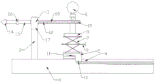
图1为本发明结构示意图;Fig. 1 is a structural representation of the present invention;
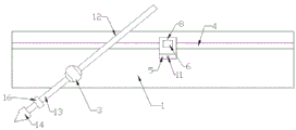
图2为本发明俯视图;Fig. 2 is a top view of the present invention;
图3为本发明正常工作原理示意图;Fig. 3 is a schematic diagram of the normal working principle of the present invention;
图4为本发明异常工作原理示意图;Fig. 4 is a schematic diagram of the abnormal working principle of the present invention;
附图标记:1、支撑座,2、支撑杆,3、万向球,4、滑轨,5、滑座,6、检测表,7、伸缩架,8、工作台,9、调节丝杠,10、滚珠,11、紧固螺栓,12、测量杆,13、校正杆,14、校正头,15、螺纹连接孔,16、配重螺母,17、转向座,18、减重腔,19、工件。Reference signs: 1, support seat, 2, support rod, 3, universal ball, 4, slide rail, 5, sliding seat, 6, inspection table, 7, telescopic frame, 8, workbench, 9, adjusting screw , 10, ball, 11, fastening bolt, 12, measuring rod, 13, correction rod, 14, correction head, 15, threaded connection hole, 16, counterweight nut, 17, steering seat, 18, weight reduction cavity, 19 , Workpiece.
具体实施方式Detailed ways
实施例1Example 1
本实施例作为本发明的一较佳实施例,其公开了一种机床用零件找正装置,具体结构如图1所示,包括支撑座1和检测杆,所述支撑座1上设置有与其垂直相连的支撑杆2,所述支撑杆2为伸缩杆;所述检测杆包括测量杆12和校正杆13,测量杆12和校正杆13对称设置于万向球3的两侧,且与万向球3丝扣连接;支撑杆2上设置有与万向球3相适配的转向座,转向座与万向球之间为间隙配合,其配合精度为6级;所述万向球3两侧的测量杆12和校正杆13长度不等,其中校正杆13的长度较短,且校正杆13的端面丝扣连接有有用于固定工件的校正头14,测量杆12的长度大于校正杆13的长度,且其外形为圆柱形,且测量杆的端面上设置有螺纹连接孔15,其用于连接不同的测量杆12以延长测量杆12的长度;所述测量杆12和校正杆13既能使用密度不一致的异种材料制作,也可使用密度一致的同种材料制作,当使用同种材料时需要在校正杆13上设置配重螺母16或在测量杆12上设置减重腔18,以保证安装以后的检测杆能够在没有外力作用的静止状态下保持其轴线始终处于水平位置(其平衡原理为杠杆原理),检测杆与支撑座1之间的夹角为任意角度;所述支撑座1上还设置有滑轨4,所述滑轨4上设置有滑座5,所述滑座5与滑轨4之间通过滚珠10实现滑动连接,所述滑座5上设置有伸缩架7,伸缩架7上设置有调节丝杠9,调节丝杠上设置有两段螺纹旋向相反的调节螺纹,从而实现对伸缩架7伸缩状态的调节,所述伸缩架7顶部固定设置有工作台8,所述工作台8上设置有用于测量检测杆偏移量的检测表6;所述滑座5上还设置有用于将其固定于支撑座1上的紧固螺栓11,所述检测表6采用百分表或千分表,其检测头与测量杆12的外表面相接触。This embodiment, as a preferred embodiment of the present invention, discloses a part alignment device for machine tools. The specific structure is shown in Figure 1, including a support base 1 and a detection rod. Vertically connected support rod 2, the support rod 2 is a telescopic rod; the detection rod includes a
实施例2Example 2
本实施例作为本发明的又一较佳实施例,其公开了一种机床用零件找正装置,其万向球3与转向座17之间为间隙配合,其配合精度为7级;所述检测表6为红外线探测器,其探测头与测量杆12之间的夹角为锐角、直角或钝角。This embodiment, as another preferred embodiment of the present invention, discloses a part alignment device for machine tools, the universal ball 3 and the
本发明的工作过程:首先将本装置滑动安装于机床上,并保证机床主轴与本装置检测杆的轴线重合,再将待校正零件安装于机床的主轴上,通过校正头顶撑工件19端面的中心坑,再将本装置固定于机床上,同时将检测表的读数归零;再手动旋转机床主动轴,通过观察检测表的测量数据即可判断主轴轴线是否与工件轴线重合,并及时校正。The working process of the present invention: firstly, the device is slidably installed on the machine tool, and the axis of the detection rod of the machine tool and the detection rod of the device are guaranteed to coincide, and then the parts to be corrected are installed on the main shaft of the machine tool, and the center of the end surface of the
本发明的工作原理:由于本发明的检测杆轴线与机床主轴轴线重合(如图3所示),如果工件19安装以后其轴线与主轴轴线重合,则机床主轴轴线、工件轴线和检测杆轴线重合,在工件19旋转时将会带动检测干绕其轴线旋转,此时检测表的检测数据为零,表明工件处于正确的安装工位;Working principle of the present invention: since the axis of the detection rod of the present invention coincides with the axis of the spindle of the machine tool (as shown in Figure 3), if the axis of the
如果工件安装以后其轴线偏离主轴轴线,则工件19轴线与检测杆轴线也发生偏离(如图4所示),此时工件19与检测杆偏心连接,因此工件19会带动检测杆绕万向球做旋转运动(如图4所示),此时检测杆发生偏离,检测杆与检测表之间的间距发生改变,此时检测表检测到该偏离数值,表明工件处于错误的安装工位,需要调整。If the axis of the workpiece deviates from the spindle axis after installation, the axis of the
Claims (4)
Priority Applications (1)
| Application Number | Priority Date | Filing Date | Title |
|---|---|---|---|
| CN201811129926.5A CN109015108B (en) | 2018-09-27 | 2018-09-27 | Alignment device for machine tool parts |
Applications Claiming Priority (1)
| Application Number | Priority Date | Filing Date | Title |
|---|---|---|---|
| CN201811129926.5A CN109015108B (en) | 2018-09-27 | 2018-09-27 | Alignment device for machine tool parts |
Publications (2)
| Publication Number | Publication Date |
|---|---|
| CN109015108A CN109015108A (en) | 2018-12-18 |
| CN109015108B true CN109015108B (en) | 2023-07-14 |
Family
ID=64618621
Family Applications (1)
| Application Number | Title | Priority Date | Filing Date |
|---|---|---|---|
| CN201811129926.5A Expired - Fee Related CN109015108B (en) | 2018-09-27 | 2018-09-27 | Alignment device for machine tool parts |
Country Status (1)
| Country | Link |
|---|---|
| CN (1) | CN109015108B (en) |
Families Citing this family (5)
| Publication number | Priority date | Publication date | Assignee | Title |
|---|---|---|---|---|
| CN110542377B (en) * | 2019-09-17 | 2021-05-28 | 青岛迈朗格金属加工配送有限公司 | Detection and measurement quick alignment device for heavy truck spare parts production |
| CN110885170A (en) * | 2019-12-12 | 2020-03-17 | 天津工程机械研究院有限公司 | Belt type dewatering machine deviation rectifying detection device |
| CN111250802B (en) * | 2020-02-28 | 2021-05-04 | 重庆机床(集团)有限责任公司 | Double-station machine tool workpiece spindle positioning method and device |
| CN111644878B (en) * | 2020-06-02 | 2021-07-16 | 大连理工大学 | A device and method for accurate and fast alignment of rotary parts on-machine |
| CN112318180B (en) * | 2020-09-22 | 2022-07-15 | 成都飞机工业(集团)有限责任公司 | Alignment tool and method for machining part with closed angle |
Citations (12)
| Publication number | Priority date | Publication date | Assignee | Title |
|---|---|---|---|---|
| CN201208706Y (en) * | 2008-06-20 | 2009-03-18 | 聂福全 | Mechanical lever type center corrector for center lathe |
| CN103644801A (en) * | 2013-11-16 | 2014-03-19 | 无锡麦铁精密机械制造有限公司 | Connection rod detection testing fixture |
| CN203804683U (en) * | 2014-05-16 | 2014-09-03 | 山东豪迈机械科技股份有限公司 | Orthogonal measurement device for workpiece machining of numerical-controlled machining center |
| CN105043320A (en) * | 2015-07-07 | 2015-11-11 | 北方华安工业集团有限公司 | Lever magnetic force alignment device |
| CN105180765A (en) * | 2015-09-07 | 2015-12-23 | 成都飞机工业(集团)有限责任公司 | Internal measuring lever type dial gauge combination boring machine alignment measuring tool |
| CN105290880A (en) * | 2015-11-27 | 2016-02-03 | 东方电气集团东方汽轮机有限公司 | Device and method for detecting perpendicularity of axis of spindle and reference axis in movement |
| KR20160136136A (en) * | 2015-05-19 | 2016-11-29 | 두산공작기계 주식회사 | Method of correcting spindle positions of head attachments for machining tools and machining tool in which spindle positions of head attachments are automatically corrected based on installation errors |
| CN106500574A (en) * | 2016-11-25 | 2017-03-15 | 无锡贺安特动力科技有限公司 | Arrangement for measuring verticality |
| CN106553073A (en) * | 2015-09-29 | 2017-04-05 | 于平 | A kind of accurate tool changer mechanical arm tool change position adjusts instrument |
| CN206862271U (en) * | 2016-07-29 | 2018-01-09 | 中石化石油机械股份有限公司三机分公司 | A kind of detection means for being used to detect crosshead screwed hole and outer circles |
| CN207180578U (en) * | 2017-08-29 | 2018-04-03 | 平湖市宇达精密机械有限公司 | A kind of cubing for measuring inner hole of workpiece circle bounce |
| CN208841043U (en) * | 2018-09-27 | 2019-05-10 | 四川职业技术学院 | A kind of lathe part alignment device |
-
2018
- 2018-09-27 CN CN201811129926.5A patent/CN109015108B/en not_active Expired - Fee Related
Patent Citations (12)
| Publication number | Priority date | Publication date | Assignee | Title |
|---|---|---|---|---|
| CN201208706Y (en) * | 2008-06-20 | 2009-03-18 | 聂福全 | Mechanical lever type center corrector for center lathe |
| CN103644801A (en) * | 2013-11-16 | 2014-03-19 | 无锡麦铁精密机械制造有限公司 | Connection rod detection testing fixture |
| CN203804683U (en) * | 2014-05-16 | 2014-09-03 | 山东豪迈机械科技股份有限公司 | Orthogonal measurement device for workpiece machining of numerical-controlled machining center |
| KR20160136136A (en) * | 2015-05-19 | 2016-11-29 | 두산공작기계 주식회사 | Method of correcting spindle positions of head attachments for machining tools and machining tool in which spindle positions of head attachments are automatically corrected based on installation errors |
| CN105043320A (en) * | 2015-07-07 | 2015-11-11 | 北方华安工业集团有限公司 | Lever magnetic force alignment device |
| CN105180765A (en) * | 2015-09-07 | 2015-12-23 | 成都飞机工业(集团)有限责任公司 | Internal measuring lever type dial gauge combination boring machine alignment measuring tool |
| CN106553073A (en) * | 2015-09-29 | 2017-04-05 | 于平 | A kind of accurate tool changer mechanical arm tool change position adjusts instrument |
| CN105290880A (en) * | 2015-11-27 | 2016-02-03 | 东方电气集团东方汽轮机有限公司 | Device and method for detecting perpendicularity of axis of spindle and reference axis in movement |
| CN206862271U (en) * | 2016-07-29 | 2018-01-09 | 中石化石油机械股份有限公司三机分公司 | A kind of detection means for being used to detect crosshead screwed hole and outer circles |
| CN106500574A (en) * | 2016-11-25 | 2017-03-15 | 无锡贺安特动力科技有限公司 | Arrangement for measuring verticality |
| CN207180578U (en) * | 2017-08-29 | 2018-04-03 | 平湖市宇达精密机械有限公司 | A kind of cubing for measuring inner hole of workpiece circle bounce |
| CN208841043U (en) * | 2018-09-27 | 2019-05-10 | 四川职业技术学院 | A kind of lathe part alignment device |
Also Published As
| Publication number | Publication date |
|---|---|
| CN109015108A (en) | 2018-12-18 |
Similar Documents
| Publication | Publication Date | Title |
|---|---|---|
| CN104132605B (en) | A kind of device for the detection of turntable frame axiality | |
| CN207963779U (en) | A kind of laser displacement sensor calibrating installation | |
| CN102607433B (en) | Multi-point detection device for thickness of bearing bush | |
| CN109015108A (en) | A kind of lathe part alignment device | |
| CN205228343U (en) | But in simultaneous measurement bearing / instrument of outer raceway lasso size and angle | |
| CN206019518U (en) | There are the high accuracy circular jitter detection apparatus of size compatibility | |
| CN205614070U (en) | Machine tooling equipment rotation axis rotation center calibrating device | |
| CN108180812B (en) | A kind of bearing radial internal clearance measuring device and measurement method | |
| CN103341789B (en) | Sensor position adjusting device for spindle rotation error detection | |
| CN105290880B (en) | A kind of device and method detecting verticality between main-shaft axis and datum axis movement | |
| CN205228353U (en) | Outer lane roundness detection device in bearing | |
| CN207570428U (en) | Suitable for the end face run-out cubing of axial workpiece | |
| CN205138399U (en) | Screw hole and terminal surface straightness detection device that hangs down | |
| CN108458639A (en) | A kind of aircraft attachment axial gap measuring device and axial gap measurement method | |
| CN209043253U (en) | A small hole diameter measuring device for industrial engineering | |
| CN108061503B (en) | Method for detecting outer diameter of conical part on length measuring instrument | |
| CN101979954B (en) | Measuring tool for measuring arc parts | |
| CN208841043U (en) | A kind of lathe part alignment device | |
| CN203418369U (en) | Sensor position adjusting device for rotation error detection of main shaft | |
| CN217032422U (en) | A device for detecting coating thickness of marine engineering materials | |
| CN114264267B (en) | Ultra-precise angle sensor circumference angle detection system | |
| CN205332940U (en) | Raceway measuring apparatu is synthesized to bearing | |
| CN115077332A (en) | A rapid detection device for bracket bearing hole end surface distance | |
| CN205254688U (en) | Precision machine tool main shaft gyration accuracy testing device | |
| CN213455248U (en) | A workpiece height and flatness detection jig |
Legal Events
| Date | Code | Title | Description |
|---|---|---|---|
| PB01 | Publication | ||
| PB01 | Publication | ||
| SE01 | Entry into force of request for substantive examination | ||
| SE01 | Entry into force of request for substantive examination | ||
| GR01 | Patent grant | ||
| GR01 | Patent grant | ||
| CF01 | Termination of patent right due to non-payment of annual fee | ||
| CF01 | Termination of patent right due to non-payment of annual fee |
Granted publication date: 20230714 |