CN1089849C - Arrangement in two cycle combustion engine with internal combustion - Google Patents
Arrangement in two cycle combustion engine with internal combustion Download PDFInfo
- Publication number
- CN1089849C CN1089849C CN98804487A CN98804487A CN1089849C CN 1089849 C CN1089849 C CN 1089849C CN 98804487 A CN98804487 A CN 98804487A CN 98804487 A CN98804487 A CN 98804487A CN 1089849 C CN1089849 C CN 1089849C
- Authority
- CN
- China
- Prior art keywords
- piston
- sine
- cylinder
- shape
- cam guide
- Prior art date
- Legal status (The legal status is an assumption and is not a legal conclusion. Google has not performed a legal analysis and makes no representation as to the accuracy of the status listed.)
- Expired - Fee Related
Links
Images


Classifications
-
- F—MECHANICAL ENGINEERING; LIGHTING; HEATING; WEAPONS; BLASTING
- F01—MACHINES OR ENGINES IN GENERAL; ENGINE PLANTS IN GENERAL; STEAM ENGINES
- F01B—MACHINES OR ENGINES, IN GENERAL OR OF POSITIVE-DISPLACEMENT TYPE, e.g. STEAM ENGINES
- F01B9/00—Reciprocating-piston machines or engines characterised by connections between pistons and main shafts and not specific to preceding groups
- F01B9/04—Reciprocating-piston machines or engines characterised by connections between pistons and main shafts and not specific to preceding groups with rotary main shaft other than crankshaft
- F01B9/06—Reciprocating-piston machines or engines characterised by connections between pistons and main shafts and not specific to preceding groups with rotary main shaft other than crankshaft the piston motion being transmitted by curved surfaces
-
- F—MECHANICAL ENGINEERING; LIGHTING; HEATING; WEAPONS; BLASTING
- F01—MACHINES OR ENGINES IN GENERAL; ENGINE PLANTS IN GENERAL; STEAM ENGINES
- F01B—MACHINES OR ENGINES, IN GENERAL OR OF POSITIVE-DISPLACEMENT TYPE, e.g. STEAM ENGINES
- F01B3/00—Reciprocating-piston machines or engines with cylinder axes coaxial with, or parallel or inclined to, main shaft axis
- F01B3/04—Reciprocating-piston machines or engines with cylinder axes coaxial with, or parallel or inclined to, main shaft axis the piston motion being transmitted by curved surfaces
-
- F—MECHANICAL ENGINEERING; LIGHTING; HEATING; WEAPONS; BLASTING
- F02—COMBUSTION ENGINES; HOT-GAS OR COMBUSTION-PRODUCT ENGINE PLANTS
- F02B—INTERNAL-COMBUSTION PISTON ENGINES; COMBUSTION ENGINES IN GENERAL
- F02B41/00—Engines characterised by special means for improving conversion of heat or pressure energy into mechanical power
- F02B41/02—Engines with prolonged expansion
- F02B41/04—Engines with prolonged expansion in main cylinders
-
- F—MECHANICAL ENGINEERING; LIGHTING; HEATING; WEAPONS; BLASTING
- F02—COMBUSTION ENGINES; HOT-GAS OR COMBUSTION-PRODUCT ENGINE PLANTS
- F02B—INTERNAL-COMBUSTION PISTON ENGINES; COMBUSTION ENGINES IN GENERAL
- F02B75/00—Other engines
- F02B75/26—Engines with cylinder axes coaxial with, or parallel or inclined to, main-shaft axis; Engines with cylinder axes arranged substantially tangentially to a circle centred on main-shaft axis
-
- F—MECHANICAL ENGINEERING; LIGHTING; HEATING; WEAPONS; BLASTING
- F02—COMBUSTION ENGINES; HOT-GAS OR COMBUSTION-PRODUCT ENGINE PLANTS
- F02B—INTERNAL-COMBUSTION PISTON ENGINES; COMBUSTION ENGINES IN GENERAL
- F02B75/00—Other engines
- F02B75/28—Engines with two or more pistons reciprocating within same cylinder or within essentially coaxial cylinders
- F02B75/282—Engines with two or more pistons reciprocating within same cylinder or within essentially coaxial cylinders the pistons having equal strokes
-
- F—MECHANICAL ENGINEERING; LIGHTING; HEATING; WEAPONS; BLASTING
- F02—COMBUSTION ENGINES; HOT-GAS OR COMBUSTION-PRODUCT ENGINE PLANTS
- F02B—INTERNAL-COMBUSTION PISTON ENGINES; COMBUSTION ENGINES IN GENERAL
- F02B75/00—Other engines
- F02B75/02—Engines characterised by their cycles, e.g. six-stroke
- F02B2075/022—Engines characterised by their cycles, e.g. six-stroke having less than six strokes per cycle
- F02B2075/025—Engines characterised by their cycles, e.g. six-stroke having less than six strokes per cycle two
Abstract
A combustion engine (10) has a number of engine cylinders (21-1 - 21-5) arranged in an annular series around a common middle drive shaft (11) with the cylinder axes running parallel to the drive shaft. Each cylinder includes a pair of pistons (44, 45) movable towards and away from each other, which work in a common, intermediate working chamber (K). Each piston (44, 45) forms - via a piston rod (48, 49) with associated support roll (53) - support and control via a 'sine' - plane ('sine' - curve (8a, 8b)) in a cam guide device. The two pistons (44, 45) in each cylinder (21; 21-1 - 21-5) have mutually differing piston phases, which are controlled by mutually differing cam guide devices. The cam guide devices are designed with equivalent mutually differing 'sine' - planes ('sine' - curves (8a, 8b)).
Description
The present invention relates to one in the two-stroke internal-combustion engine and arrange (arrangement), this internal-combustion engine comprises a plurality of engine cylinders, these cylinders are arranged to an annular series and its cylinder axis is parallel to live axle around a common center live axle, each cylinder comprises can be toward each other and mutually liftoff mobile pair of pistons, each has a public intermediate working chamber to piston, each piston is equipped with axially movable piston rod simultaneously, free outer end one idler pulley of piston rod constitutes a supporting member, curved to support one, " sine " curved cam guide in other words, described cam guide is arranged in each opposite end of cylinder and piston is led with respect to the motion of respective cylinder.The geometry of aforementioned engine system (geometric) is considered
When the live axle of motor moves in a circular path, but observe on the figure aforementioned engine system engine piston reciprocal (oscillation) motion with respect to the time for based on a sinusoidal curve of following formula:
Formula 1:Y=sine X.
Can formerly know the two-cycle engine of previous described type by DE 4335515, it has with a single cylinder of two opposed pistons and traditional bent axle and traditional crankweb.
By adopting a sine-shaped, sinusoidal cam guide and correspondingly adopting traditional bent axle, in fact can control in the cylinder each piston backward and motion forward (seesawing), thereby the to-and-fro motion of piston can be synchronously consistent with rotatablely moving of live axle.In one of live axle complete rotation process, piston with one forcibly the mode of control in one or more working strokes, seesaw, this seesaws accurately synchronous with rotatablely moving of live axle.In other words, rotatablely moving of cam guide and live axle will directly be associated with the to-and-fro motion of piston, and vice versa.
Seesawing of piston will correspondingly constitute the repeatedly rotation of live axle, 360 ° of wherein each drive shaft turns.In other words each piston total number of times that will seesaw in corresponding cylinder, promptly from 1 time to for example 4 times, wherein live axle is done 360 ° rotation each time.
Since control piston in corresponding cylinder reciprocating cam guide and the live axle of motor synchronously rotate, therefore can the to-and-fro motion of control piston by design a sine-shaped curved profile to cam guide, thus make the to-and-fro motion of piston meet rotatablely moving of live axle." sine " shape notion
When the term that adopts " sine " shape is herein expressed (for example " sine " shape notion, " sine " shape curve, " sine " shape plane etc.), its expression be a curved profile that does not constitute according to a mathematics sinusoidal profile of above-mentioned formula 1, and what express is a curved profile that changes, and it only is similar to the track of a mathematics sinusoidal profile substantially.Term " sine " shape profile will be meant substantially herein and be similar to but be different from the profile of a sinusoidal profile.
According to the present invention, its objective is that about configuration aspects it deviates from a mathematics sinusoidal profile in a different manner to cam guide design one special curved profile.
According to the present invention, normally this also means " sine " shape profile that designs a kind of special shape to cam guide, it deviates from a conventionally known sinusoidal profile, and piston motion can be adapted to rotatablely move and with respect to the additional duty of engine of the scheme of advising previously with respect to live axle with a corresponding manner.
According to the present invention, its basic purpose is the design cam guide, makes and can obtain optimal operation conditions can for the piston of motor based on a simple and reliable order of operation (sequence).
When mentioning " sine " shape plane herein, it is meant the local part with " sine " shape curved profile of cam guide.In fact each cam guide has one 360 ° curved profile, and it is corresponding to a plurality of described " sine " shape plane.
The combustion engine that the axial motion of piston is controlled through corresponding " sine " shape plane respectively by a cam guide is worked according to so-called " sine " shape notion usually, and this knows for many years.
" sine " shape plane has a profile that is similar to the mathematics sinusoidal profile to a great extent at first, promptly has symmetrically and evenly crooked curved portion.
According to patent documentation, curved profile proposes with the different modes that deviates from the mathematics sinusoidal profile gradually.Curved profile according to cam guide of the present invention also is this situation.
According to " sine " shape notion, mechanical energy passes to the common drive shaft of engine cylinder from single piston, promptly passes to " sine " shape plane of cam guide through the idler pulley of a respective piston.Reciprocating these " sine " shape planes of control piston are in the to-and-fro motion process of piston respectively:
-through " sine " shape plane kinetic energy is partly passed to live axle from the expansion stroke of piston, thereby make live axle rotate with corresponding torque and
-through " sine " shape plane torsional moment is partly passed to piston from live axle, thus make piston in compression stroke, bear necessary kinetic energy.
In the combustion engine of introduction type, piston front and back axial motion in corresponding cylinder, along live axle axial motion almost completely as the crow flies, simultaneously piston rod and corresponding idler pulley be with the rectilinear motion mode motion of correspondence, and thereby give corresponding " sine " shape plane with the transfers of driving force from idler pulley along live axle.
Driving force (motive force) from piston through the transmission of idler pulley to " sine " shape plane, this is designed in the driving of relevant live axle, and the transmission of the return force (return force) that transmits to piston through " sine " shape plane along opposite direction from live axle, appear on the curved portion of extension obliquely of plane of rotation of live axle.In other words, driving force is along transmitting in the axial displacement process of live axle between idler pulley and " sine " shape plane, at idler pulley.But the transmission of driving force can not appear in place, the dead point between the stroke of piston that seesaws, although at place, dead point, promptly finish and after the fuel that sprays lighted a fire in compression stroke, can be toward each other and occur very big driving force between the piston of mutually liftoff motion.
Special purpose of the present invention is to utilize the above-mentioned last condition relevant with the particular design of cam guide, thereby the place can obtain a possibility of not considering as yet so far at described dead point, to such an extent as to control the combustion process of motor with a particularly advantageous mode.The comparison of four-stroke and two-cycle engine
In a four-stroke combustion motor, piston rod is through " sine " shape plane transmission of drive force in corresponding 4 strokes, promptly
-minimum the power of transmission in suction stroke,
-bigger the power of transmission in compression stroke,
-in expansion stroke, transmit maximum power and
-minimum the power of transmission in exhaust stroke.
In one or two stroke combustion motor, piston rod is through " sine " shape plane transmission of drive force in corresponding 2 strokes, promptly
-in air inlet and the compression stroke of a combination the relative less power of transmission and
-remarkable bigger the power of transmission in an expansion of making up and compression stroke.
But usually also allow expansion in combination to finish and when the air inlet of combination began with compression stroke, air-breathing/air inlet of appearance and exhaust more or less walked abreast with exhaust stroke.
Up to now, four stroke engine has the use of prevailing market with respect to two-cycle engine basically in many different applications (petrol engine that for example is used for personal car).Operative strokes as four stroke engine is distributed in four results on the stroke of piston, have the prospect that better adapts to each function of single stroke than a two-cycle engine in a better simply mode, wherein current function must adapt to two strokes in the two-cycle engine.
Two-cycle engine must be compacter thereby also just more complicated than the function of four stroke engine.Four stroke engine is so far than also simpler " sine " shape notion that is suitable for of two-cycle engine.Two-cycle engine has various other advantages with respect to four stroke engine on the other hand, exactly is because the result of the operative strokes of lesser amt.
The objective of the invention is especially will solve two-cycle engine in the problem that is had so far aspect application " sine " shape notion.According to the present invention, its objective is in a special mode and design cam guide, thus can be in two-cycle engine, corresponding favourable or than four stroke engine even better adopt " sine " shape notion under the operational condition." sine " shape conception development history
Can learn a four-stroke combustion motor from for example US 1352985 (1918), it has a single cam guide.This cam guide is based on a unique public cam control, is used to be controlled at the piston of the unique annular series in corresponding each engine cylinder.Each cylinder and all cylinders all correspondingly are arranged to a unique annular series around the live axle of motor.Piston rod is bearing in respectively in the public cam guide through its corresponding idler pulley.
Can know a for example four-stroke combustion motor by US 1802902 (nineteen twenty-nine), it has a corresponding single cam guide.In this case, replace the only piston of a series, it adopts axially-spaced but is coupled to each other the piston of two series together.Before and after the piston tandem ground be arranged in its corresponding axially relatively towards cylinder in, promptly cylinder and piston in pairs alignedly, axially setting relatively each other.Piston also interconnects rigidly by a shared piston rod, and accordingly each piston head at engine shaft away from each other to relative end, the corresponding work chamber in its respective cylinder respectively.The zone line of the shared piston rod of every pair of piston between the skirt section of piston is provided with a shared idler pulley, and this idler pulley is supported and is controlled in the shared unique cam guide of all pistons.More particularly, the cam guide that adopts central authorities to be provided with, this guiding device has " sine " respect to one another shape plane of the bilateral setting that is series, and these planes and a single idler pulley series match.
Aforementionedly between two piston series respect to one another, cam guide and idler pulley are set medially, wherein in a shared bilateral cam guide, adopted a single idler pulley series, it produces profile hardly and departs from two opposed facing " sine " shape plane series that match, because behind the relative working stage of right corresponding two the opposed facing pistons of piston, the profile on " sine " shape plane has been adjusted necessarily.
Can know a for example four-stroke combustion motor by US 5031581 (1989), it has two independent cam guide.Its corresponding one group of piston and accordingly that each cam guide of matching of group idler pulley design corresponding to structure respectively according to US 1352985.
According to US 5031581, cylinder is arranged to one single group of cylinder, and promptly cylinder is arranged to a single annular series around live axle.Be contained in couples in the corresponding cylinder piston by two independently cam guide operate (serve), be that each is controlled by one first cam guide a piston in the piston, remaining piston is then controlled by one second cam guide.Therefore each cylinder be equipped with can be in couples toward each other with the mutually liftoff mobile piston that separates, they have independently piston rod, this piston rod respectively through a corresponding idler pulley and with two relative cam guide that have corresponding " sine " shape plane in corresponding one match.Two axially not on the same group the cam guide of piston axially be arranged in the outside of the respective end of motor in endways ground (endwise).The right piston head of described piston is used active chamber altogether in the corresponding cylinder each other, promptly towards be arranged on described piston between the public active chamber in neutral position.
In GB 2019487, show one 4 cylinder two-cycle engines, its have a pair of in described four cylinders toward each other with mutually liftoff mobile piston.Adopted so a kind of layout, wherein side by side lighted a fire among two in four cylinders, be i.e. igniting simultaneously in a pair of cylinder that replaces.The profile of pointing out cam in this patent specification can design like this, to such an extent as to piston can move in the inflation process of products of combustion in a best mode.Adopted a profile extend of hope or stable, with emptying or blow down gas before in cylinder, introducing new fuel.Show the more or less straight local cam profile in each in two relative cam paths in the drawings, this part cam profile locates to form " sine " shape curved portion at the point (turning point) that mutuallys transfer that directly relatively is provided with each other.More particularly, straight cam profile only is illustrated in one of two transit points that continue of " sine " shape curved portion of formation " sine " shape curve and locates, promptly one after the other occupy its outer end position place farthest in corresponding piston, this moment, relief opening and scavenge port were opened at utmost.The present invention
Relate to the present invention of two-stroke cycle motor, in a foru cycle engine, to have layout according to the piston of aforementioned US 5031581 and cylinder arrangement as its starting point.Particularly the objective of the invention is in a two-cycle engine, to be suitable for " sine " shape notion, thus can obtain than obtained in four stroke engine according to US 5031581 be favourable comparably and preferably even more favourable operational condition at least.
In a four stroke engine, one after the other adopt 4 other strokes of branch (aspirating stroke, compression stroke, expansion stroke and exhaust stroke), thereby in each stroke, can adapt to the different duties of engine, and in a two-cycle engine, exhaust and air inlet are the transition zones that occurs between expansion stroke and the compression stroke, promptly occur in each order of work in the position that directly links to each other of the remaining duty of engine.Therefore for one or two stroke cycle engine, the different function of two strokes that relatively carry out must make up.
According to the present invention, its purpose also in one or two stroke cycle engine in a particularly advantageous mode, so that the various duties of engine are made up in the special design that for example will describe in more detail below on piston " sine " shape plane.
Especially the objective of the invention is, correspondingly as according to shown in one or two stroke cycle engine of GB 2019487, adopt a more or less straight profile at the transit point place that forms " sine " shape curved portion, be in its outer end position farthest at this place's piston, make relief opening and scavenge port be opened to maximum degree.
According to the present invention, adopt following combination:
-" sine " shape plane need not have a curved profile, its (only need) as much as possible or most probable approach but can deviate to a great extent on the contrary one " sine " shape profile and aforementioned known to those " sine " shape profiles and
-cam guide can be designed " sine " shape plane, and it can change to a great extent mutually, and still can fully obtain a particularly advantageous motor scheme.
Arrangement according to the invention is characterised in that two pistons in each cylinder have different piston stage (phase mutually, phase), these piston stages are by different mutually cam guide control, these cam guide are designed mutual different " sine " shape plane of equity, the corresponding cam guide of two pistons has phase displacement relative to one another in some part on " sine " shape plane, and the remaining part on " sine " shape plane then has common phase place.
Can obtain a particularly advantageous control according to the present invention, thus with can particularly advantageously adapt to work functions different in one or two stroke cycle engine.
Particularly, can adapt in the top of " sine " curve and/or the work functions of bottom, and can one public or more or less public mode is arranged corresponding centre " sine " shape curved portion in mutual different mode.
Therefore all pistons that can guarantee piston pair according to the present invention move in a mutual different mode, but still can obtain favourable intensive work condition in the public active chamber between the right piston head of piston.The phase displacement of cam guide (phase displacement)
Obtain the particularly advantageous scheme of a reality according to the present invention, wherein each cam guide of two pistons some part on " sine " shape plane has phase displacement (being phase-state change) relative to one another.
This means, at first, according to a first aspect of the present invention, having can be with respect to ensuing compression stage, the possibility of extending its combustion phase with respect to expansion stage the preceding respectively, and its mode is by phase displacement is carried out at the top of " sine " shape curve.
According to a second aspect of the present invention, can obtain one of scavenge port favourable independently control through the cam guide of a piston, can obtain a corresponding favourable independently control through the cam guide of another piston to relief opening.Therefore, for example by such phase displacement, can obtain scavenge port and relief opening the opening and close of each time point (points in time), and can determine these time points by designing each cam guide on a 50-50 basis.
In another way, two pistons can open and close corresponding mouthful (relief opening/scavenge port) independently, corresponding piston then occupies the axial position of the correspondence in the respective cylinder, but by the mutual phase displacement between the piston motion, can open and close various mouthfuls corresponding to the phase place in-migration.The particular design on " sine " shape plane
By designing described " sine " shape planar section as the crow flies or to a great extent as the crow flies, obtained a possibility that reckons without so far of particularly advantageous operating conditions in the combustion phase of fuel with place, the rectangular plane of the live axle of motor.According to the present invention, in fact the design especially by to " sine " shape plane can limit the special burning cavity corresponding to described active chamber part in active chamber.Therefore this burning cavity can have a constant or almost constant volume at one of the longitudinal size on " sine " shape plane on the circular arc on big arc length and rotating of live axle, thereby can carry out most, whole or whole to a great extent combustion process for example in described burning cavity.
When being meant that herein burning cavity can have a constant or constant to a great extent volume, then this is relevant with detail design on " sine " shape plane at place, dead point between compression stroke and expansion stroke.
In other words, the straight part of an arc in " sine " shape plane can obtain corresponding constant volume, and for a more or less straight part, then can obtain the constant to a great extent volume of equity.This comprises the profile that can adjust " sine " shape plane according to the physical condition in the application of different situations.
In fact can adopt straight " sine " shape planar section of part and part at preceding and straight to a great extent " sine " shape planar section that continue.
Pass through aforementioned schemes, this scheme has a constant or burning cavity of constant volume to a great extent based on the position, a dead point at the crossover position from the compression stroke to the expansion stroke, the concentrated energy that at first just can select to utilize in combustion process and produced, and even the beginning in the expansion stage just can have whole power.Therefore after corresponding piston had moved through its dead point or dead point part, described energy can immediately be utilized fully.Therefore can be to utilize this release of energy in the existing full intensity of the transition portion of described bending, wherein at the transition portion of described bending, piston accelerates to best piston motion and after this continues to move with very big intensity in the ensuing expansion stage from static.
Secondly, adopt such burning cavity, can obtain, promptly to the most burning of fuel, even before the expansion stage begins to one of fuel more favourable burning with constant volume.This can guarantee by the sizable part in the burning cavity combust fuel of described dead point part.
In addition, by finishing expansion stroke before the active chamber combustion gas, in active chamber, guarantee to consume (burning) big percentage partly fuel and can obtain a better utilization to fuel energy.
In other words, can increase the output (power) of motor to a great extent according to the present invention with respect to known arrangement.
Therefore obtained a bigger substantially motor exports according to the present invention.Reduce the discharging of CO (carbon monoxide) gas, NOX (nitrogen oxides) gas and analog in addition, and also obtained a burning that better is of value to environment thus.
Also it should be noted that the after burning of fuel, it appears in the expansion stroke itself, and can compensate expansion to a great extent at that part of volume of active chamber generation reciprocating motion of the pistons, according to the present invention this after burning can with one control the appropriate moment of mode before Exhaust Open carry out, promptly along with expansion stroke this in active chamber carrying out and little by little carry out.
In other words, can with a favourable mode from expansion stroke begin to distribute driving force, and take a step forward at Exhaust Open and to distribute through sizable part of expansion stroke even with an existing optimum fuel before expansion stroke.
Therefore by can be released with full intensity from a burning cavity relatively immediately from the energy that the motion of state of rest release plunger discharges with a constant volume.This release itself can occur in a mode of quickening through " sine " shape planar section of a bending, and " sine " shape planar section that wherein should bending is formed in the transition portion between the straight dilation that described straight dead point part and continues.At ensuing straight dilation, expand linearly, promptly an active chamber internal linear ground that increases volume linearly expands having taking it by and large.
The description of accompanying drawing
In conjunction with the drawings can obvious further feature of the present invention by following description, these accompanying drawings have been represented the embodiment that some is actual, wherein:
Fig. 1 represents the vertical section according to a motor of the present invention.
One appropriate section of the vitals of the motor of Fig. 1 a and 1b presentation graphs 1, and Fig. 1 a represents to be in and has the maximum engine piston of interval location mutually, and Fig. 1 b represents to be in the engine piston with position, minimum space.
Fig. 2 is shown schematically in one first section of engine cylinder one end, wherein shows ventilation (scavenging air) inlet.
Fig. 3 is shown schematically in one second section of the engine cylinder the other end, wherein shows an exhaust outlet.
Fig. 4 a is shown schematically in one the 3rd section of engine cylinder intermediate portion, fueling and fuel lighted a fire herein wherein, and it represents one first embodiment's situation.
Fig. 4 b represents the section corresponding to Fig. 4 a according to the intermediate portion of one second embodiment's cylinder.
Fig. 5 a represents the longitudinal profile according to the engine section of Fig. 1 b.
Fig. 5 b represents to have a cam guide of respective drive axle, and it is illustrated in the longitudinal profile according to the engine section of Fig. 1 b.
Fig. 5 c represents the side view of a crosshead.
When Fig. 5 d and 5e represent respectively from upper and lower watching according to the crosshead of Fig. 5 c.
Fig. 5 f represents the side view of piston rod.
Figure g represents when watching the piston rod according to Fig. 5 f.
Fig. 5 h represents the vertical section according to a piston of the present invention.
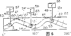
What Fig. 6~8 schematically showed first piston in two pistons relevant with each cylinder of one 3 Cylinder engines describes and is deployed in overall movement figure in the figure paper plane, and is illustrated in the different amount position with respect to drive shaft turns.
Fig. 6 a is shown schematically in the principle of transferring power between the corresponding diagonally extending part on piston rod cylinder and " sine " shape plane.
Fig. 9 schematically show one 5 Cylinder engines each cylinder two pistons describe and be deployed in a more detailed motion diagram in the figure paper plane, and be illustrated in different amount position with respect to drive shaft turns.
Figure 10 represents the figure corresponding to Fig. 9, wherein is in the working position of continuing at the piston with respect to each position of respective cylinder.
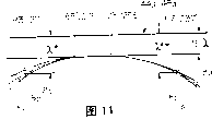
Figure 11 schematically shows the fragment of a middle body on one " sine " shape plane of two respective pistons that are used for each cylinder.
Figure 12 represents to be used for the detailed curved profile on one " sine " shape plane of the first piston in each cylinder.
Figure 13 represents to be used for the corresponding curved profile in detail on one " sine " shape plane of one second piston in each cylinder.
Figure 14 represents the contrast situation according to the curved profile of Figure 12 and 13.
The outer end that Figure 15 is illustrated in a piston rod has the longitudinal profile of a modification structures of a cam guide of relevant pressure cylinder.
Figure 16 represents and identical flexible program shown in Figure 15 that its expression is from a section of cam guide radially outward direction.
Figure 17 and 18 represents vertical section and horizontal section that the head of piston rod is led along a pair of controlling rod that extends of being parallel to each other respectively.
With reference to Fig. 1, one 2 stroke cycle internal-combustion engines 10 have been described.Especially description is suitable for such motor 10 of one so-called " sine " shape notion.In Fig. 1, show specially according to a combustion engine 10 of the present invention, this motor is shown in section and is schematically.
According to the present invention, be in a special burning cavity K1 (referring to Fig. 1 b) who limits, to burn according to the purpose of the present invention's one first aspect, will describe in more detail below.
According to a second aspect of the present invention, its objective is and advantageously control opening and closing of relief opening 25 and scavenge port 24 in addition, will be further described below.
In the embodiment shown in fig. 1, show a live axle 11 of tubing string shape, it axially and medially passes motor 10.
Head/ cam guide 12a, 12b in the illustrated embodiment illustrates respectively and is connected respectively on the live axle 11 by its fixing device respectively.
The end 11d of live axle 11 (referring to Fig. 1 and 5a) constitutes the sleeve part of a radial deflection, has fixed cup-shaped carrier member 13 on it.This carrier member 13 is provided with a holding flange 13 ', and it is by set screw 13 " be fixed on the end 11d of live axle 11.Between the upper end face 13a of carrier member 13 shaft shoulder surface 11e relative, be limited with a pressure oil cavity 13b with one of live axle 11.Hold a compression emulsification 12b ' in this pressure oil cavity 13b slidably, this emulsification is the guide rib form that a piston forms, and its inboard from cam guide is radially projecting inward to pressure oil cavity 13b, with slidably against the outer surface of end 11d.
In order to prevent the mutual rotation between cam guide 12b and carrier member 13 and live axle 11, pass guide rib 12 ' by a series of guide finger 12 ', wherein these guide fingers 12 ' are fastened in each hole of shaft shoulder surface 11e of the end surface 13a of carrier member 13 and live axle 11.
Axially inwardly insert oil-guide device 14 in the axial bore of mutual alignment of holding flange 13 ' of the end 11d of live axle 11 and carrier member 13 in this oil-guide device 14 Oil Guide pipeline 14a, 14b and adjacent annular groove 14a ', 14b ' provide pressure oil and returning pressure oil from pipeline 11f and 11g.
By the control gear commercial commonly used of a long-range setting not shown further, control to the pressure oil cavity 13b supply pressure oil of the opposite side of cam guide 12b with from pressure oil cavity 13b returning pressure oil in a mode not shown further.
As shown in Figure 1, live axle 11 is connected on the live axle sleeve 15a and 15b of equity in the opposite end.Sleeve 15a is fixed on the cam guide 12a by set screw 15a ', and sleeve 15b then is fixed on the carrier member 13 by set screw 15b '. Sleeve 15a and 15b are installed in rotation in two relative main step bearing 16a and 16b corresponding one, and its middle (center) bearing 16a, 16b are fixed in the corresponding end cap 17a and 17b of opposite end of motor 10.
As shown in Figure 1, end cap 17a and 17b correspondingly are fixed on the middle engine cylinder body 17 by set screw 17 '.
In motor 10 inside, between end cap 17a and engine cylinder body 17, limit one first lubricant reservoir 17c, and between end cap 17b and engine cylinder body 17, limit one second lubricant reservoir 17d.Show and be linked to additional lubricating cup 17e of one on the end cap 17b and the external oil pipe 17f between lubricant reservoir 17c and lubricating cup 17e.Show a filter by suction 17g who is connected on the lubricant pipe 17h in addition, wherein this lubricant pipe 17h constitutes a connecting pipe road between lubricant reservoir 17d and the external lubrication oil device (further not illustrating).
Oil-guide device 14 is provided with the head 14c that forms a lid, and this head 14c is fixed on the end cap 17b of motor 10 by set screw 14c '.Form the seal arrangement that be positioned at the block bearing 16b outside of the head 14c formation of lid with respect to the endways (endwise) of lubricant reservoir 17c.Correspondingly be fixed with a sealing cover 14d who is positioned at the block bearing 16a outside of endways on end cap 17a, sealing lid 14d has corresponding seal ring 14e.
Therefore motor 10 substantially by a drive element, promptly a pivo table member and a driving element, promptly a nonrotational element constitutes.Drive element comprises that the live axle 11 of motor and carrier member 13 and live axle sleeve 15a, the 15b of live axle add cam guide 12a and 12b, and wherein live axle sleeve 15a and 15b are connected on the live axle 11.The nonrotational element that drives comprises the cylinder 21 that has respective pistons 44,45 of motor.
According to the present invention, can regulate by internal action one, promptly regulate the adjusting of guaranteeing engine compression ratio by between the parts of drive element, reciprocally acting on one.More specifically say so a cam guide 12b with respect to live axle 11 axially backward and shift forward, promptly at the space internal shift of the qualification of described pressure oil cavity 13a, the space defined in it is to determine by guide rib 12b ' with in the part of the oil pocket 13a of this guide rib 12b ' opposite side.
Problem in the practice is to regulate length for less motor to be several millimeters, then regulates length for bigger motor and is several centimetres.But each capacity difference in relevant work chamber has the compression effectiveness that is equal in different motors.
For example can consider as required to compression ratio have the level or step-less adjustment, to adapt to each position that for example cam guide 12b is classified to control to respect to live axle 11.This control example as can be by known electronic equipment itself, automatically carry out according to different temperature-detecting device etc.Perhaps this control can be by suitable manual the carrying out of controlling device not shown further.
By the cam guide that links to each other with the drive element of motor is regulated, just can avoid influence, promptly avoid influence mechanical connection between driving element and the drive element to the overall control of the layout of respective pistons 44, piston rod 48, main support roller 53 and secondary support roller 55.
On the other hand, cam guide is carried out this kind adjusting, just can be in the inner axial adjustment that obtains of driving element, the mode of its adjusting is that the layout of piston 44, piston rod 48, main support roller 53 and secondary support roller 55 can collectively move with respect to corresponding cylinder 21 through cam guide 12b, and irrelevant with the compression adjustment of reality.
In Fig. 1 and 1b, be illustrated by the broken lines a central authorities interval 44 ' between the piston head of normal compression ratio lower piston 44,45 when cam guide 12b occupies position shown in Figure 1.Represented the central authorities interval 44 between the piston head of piston 44,45 when the guide rib 12b ' of cam guide 12b is pushed to the shaft shoulder surface 11e that is resisted against piston rod 11 topmost by solid line ".
Shown motor 10 is divided into three fixing main units, promptly constitutes two casing member 17a, 17b that form lid of a corresponding end of an intermediary element of engine cylinder body 17 and the end that is arranged in motor 10.Therefore casing member 17b, 17c are suitable for covering its corresponding cam guide 12a, 12b, support roller 53 and 55 and the corresponding bearing in each piston rod 48,49 of engine cylinder body 17 respective end.Therefore all drivings of motor and drive element are enclosed in the motor 10 effectively and are contained in the oil sump of associated lubrication oil pocket 17c and 17d.
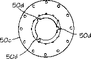
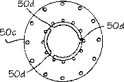
In the engine cylinder body 17 of illustrated embodiment, in one 3 Cylinder engines, correspondingly be provided with the engine cylinder 21 of 3 circumferentially spaceds.In Fig. 1,1a and 1b, only show in 3 cylinders 21.
The inserting member of the formation cylinder that is designed to separate according to illustrated embodiment with 3 cylinders 21 being spaced from each other the setting of hexagonal angle degree around live axle 11, these inserting members are pushed in the respective cylinder hole of engine cylinder body 17.
In each cylinder/cylinder spare 21, insert the cylinder axle sleeve 23 of a sleeve shape.As Fig. 1 a and 1b (also referring to Fig. 2 and 3) is shown further, in axle sleeve 23, is provided with a series of annular scavenge ports 24 at an end of this axle sleeve 23, and is provided with a series of annular row gas ports 25 at the other end of axle sleeve 23.
Be provided with scavenge port 26 on a 50-50 basis in the wall 21a of cylinder 21, scavenge port 24 radially aligneds of they and axle sleeve 23 as shown in Figure 2, are provided with the relief opening 27 with relief opening 25 radially aligneds of axle sleeve 23 simultaneously, as shown in Figure 3 on a 50-50 basis in cylinder wall 21a.
In Fig. 1, show an annular intake pipe 28 that is used to take a breath, this suction tude is around scavenge port 26, and a ventilation inlet 29 radially is positioned at the outside.
As shown in Figure 2, the ventilation mouth of pipe 28 is particularly suitable for taking a breath along a rotate path 38 in cylinder 21, shown in the arrow B among Fig. 2 to extend with respect to a radial plane A one bigger angle of inclination u that runs through cylinder axis.
Also show annular vent outlet 30 in Fig. 1, it adds the exhaust outlet 31 that radially outward is vacant around relief opening 27.
Figure 3 illustrates the relief opening 27 that a reciprocity earth tilt is extended, this tilt angle is v with respect to the angle of the radial plane A that runs through cylinder axis, waste gas is outwards drawn along the path of an equity in its path 38 that is particularly suitable for rotating in cylinder in cylinder 21, shown in an arrow C.Relief opening 27 is expressed as radially outward and opens, so that waste gas outwards flows to exhaust outlet 30 from cylinder 21.
In conventionally known mode, the air that scavenging is used is used to by the combustion phase combustion gas formerly of one in the cylinder, replenishes fresh air by the combustion process that continues of one in the cylinder in addition.At this according to the present invention, adopt a rotary air quality shown in arrow 38 (referring to Fig. 1 a and 4a) in the active chamber K in compression-stroke cylinder 21 in a manner known way.
In Fig. 1 a, 1b and 4a, show a fuel injector or nozzle 32 in the cave 33 that is contained in cylinder wall 21a.This sparger/nozzle 32 has the given end portion 32 ' protruded in the hole 34 in cylinder wall 21a (referring to Fig. 4 a).Cylinder wall 21a is passed with an angle of inclination that does not further mark among Fig. 4 a in this hole 34, but this angle is corresponding to angle u, as shown in Figure 2.Further protrude in a hole 35 in the given end portion 32 ' warp beam sleeve 23, aligns with hole 34 in the hole 35 in its Intermediate shaft sleeve.The mouth 36 of nozzle/sparger 32 (a) is so arranged referring to Fig. 4, to such an extent as to a jet flow 37 of fuel just in the preceding rotary air that can direct into shown in the arrow in the cylinder 21 38 of a spark plug 39 (can be ignition plug) with being tilted, shown in Fig. 4 a, wherein this spark plug 39 is arranged in the zone (referring to Fig. 1 b) in a chamber that constitutes a burning cavity K1 part.
In the modification structures that scheme shown in Fig. 4 a has been shown among Fig. 4 b, wherein except one first fuel nozzle 32 and one first ignition mechanism 39, one second fuel nozzle 32a and one second ignition mechanism 39a in same dish type burning cavity K1, have also been adopted.All correspondingly designs as described in Fig. 4 a of two nozzles 32 and 32a, and two ignition mechanisms 39 and 39a are also described corresponding to Fig. 4 a.Corresponding element is additional in nozzle 32a represents with reference mark " a ".
In the described embodiment of Fig. 4 b, nozzle 32,32a are expressed as being arranged on mutually on 180 ° the circular arc.Relative spacing can be adjusted as required in practice, promptly can adopt different spaces, for example depends on the time point of mutual igniting etc.
In Fig. 1, also show a cooling water system that is used for cooling cylinder 21 substantially.This cooling water system comprises a cooling water inlet not shown further, and it has one first annular cooling water pipe 41 and one second annular cooling water pipe 42. Pipeline 41,42 interconnects through the connecting tube 43 (referring to Fig. 3) that a series of ring shaped axials extend.Axially extended pipeline 43 is passed in the interior cylinder wall 21a of each zone line 27a between the relief opening 27, thereby is subjected to flowing of cooling medium and can prevents that especially these regional 27a are overheated by the part.Cooling water outlet not shown further is connected on the cooling water pipeline 42 away from the cooling water inlet in a mode not shown further among Fig. 1.
But the piston 44,45 that in axle sleeve 23, has two axial motions, they can be toward each other with from motion.Just be provided with one group of the 4th piston (pistonfourths) 46 in a manner known way near each top of piston 44a, the 44b and near shirt rim edge 44b, the 45b of piston.Piston 44,45 can be synchronized with the movement with mutually liftoff in one 2 two-stroke engine systems toward each other.
The further details of piston is illustrated among Fig. 5 h.Piston 44 is expressed as the form of a relative thin-walled cup, has top 44a and skirt section 44b.The hollow space inside of piston in be provided with a supporting disk 44c, thereafter immediately following a capitiform element 48c, the supporting ring 44d and the carrier ring 44e that are used for a respective piston 48.
Axle sleeve shape loading station 48g in the middle of capitiform element 48c is provided with one, this loading station has the fin part 48g ' that outwards laterally protrudes, and this fin partly constitutes the locking engagement with the inner reciprocity groove (further not illustrating) of respective piston 48 (referring to Fig. 1 a and 1).
At described dead center position 0a and 0b place, piston 44 exposes scavenge port 25, piston 45 then exposes relief opening 25, and opening and closing of scavenge port 24 is by the positioning control of piston 45 in respective cylinder 21, and opening and closing of relief opening 25 is by the positioning control of piston 44 in respective cylinder 21.Hereinafter will 12~14 this control be described in more detail in conjunction with the accompanying drawings.
Consider along the aforementioned adjusting of 11 couples of cam guide 12b of live axle, also will describe additional effect this control.
It is relative during than external position when piston 44,45 occupies, the interval that have a minimum between them this moment, and shown in Fig. 1 b, these positions typically refer to the dead center position.But according to the present invention, piston the 44, the 45th is fixed, and does not promptly have or do not have in a broad sense axial motion respect to one another in these dead center positions.Because piston not only all is held fixing in the dead center position but also at the contiguous position on each " sine " shape plane, therefore as will be further described below, can guarantee on the volume it more or less is constant active chamber (burning cavity) on certain precise length, promptly can guarantee this active chamber than known much longer position, " sine " shape plane.
Therefore piston 44,45 is in static or is in staticly in a broad sense at the position on " sine " shape plane, is meant " position, the dead point " 4a of piston 44 and " position, dead point " 4b of piston 45 herein.This dead point position 4a and 4b will further describe in Figure 12 and 13.
At position, described dead point, in active chamber K, define one so-called " dead space ", it is called as burning cavity K1 (below will understand its reason) herein.Burning cavity K1 mainly is limited to the compression stage of 2 two-stroke engines and the intermediate location between the expansion stage according to the present invention, will describe in more detail below.
In the expansion stage, promptly from the piston position shown in Fig. 1 b to the piston position shown in Fig. 1 a, active chamber K is from little by little being expand into by the maximum volume shown in Fig. 1 a by the minimum volume shown in the burning cavity K1, and described dead center position 0a and 0b place in Fig. 9 and 10, burning cavity K1 another chamber K2 that little by little expands wherein carries out the expansion and the compression stroke of piston 44,45.
According to the present invention, burning cavity K1 is designed into a bigger degree in the position/dead space of described dead point.Yet just also can proceed a small amount of burning actually, will narrate in more detail below in this dead space outside.
A problem relevant with the variation of compression ratio in the active chamber is that the relevant different volume in position burning cavity K1 shown in Figure 10 all can be affected in the motor using process according to adjusting.Can find out that by top description also having a problem in this case is that relevant different volume is in the relative position shown in Fig. 1 a in the burning cavity.
But the stroke of piston of each piston 44,45 of must regaining consciousness all has accurately identical length under all operational conditions, and no matter the institute must the employing compression ratio.
Each piston 44,45 is connected on its corresponding tube-shaped piston bar 48 and 49 rigidly, and wherein piston rod is directed doing straight straight line motion through a so-called crosshead control piece 50.These crosshead control piece 50 parts are arranged in the engine cylinder body 17, part is set in place in each cap member 17a and 17b of the reciprocity free outer end of each piston rod 48,49.At length illustrate as Fig. 5 a, crosshead control piece 50 constitutes just at engine cylinder body 17 inboard and the piston rod 48 in the outside and 49 axial guide devices.
With reference to Fig. 5 a, have and be fixed on one of tube-shaped piston bar 48 1 ends and ship and resell on another market 51, and this ships and resell on another market and pass piston rod 48 crosswise, promptly pass the tubular hollow space 52 of piston rod.Shipping and reselling on another market 51 intermediate portion 51a, promptly shown in hollow space 52 inside, have a main castor (castor) 53 that is rotatably mounted, and ship and resell on another market 51 be rotatably mounted an auxiliary castor 55 to the end 51b place of the side of piston rod 48 48a to the outside.
" sine " shape curved surface 54 ' be designed in the cam guide 12a of live axle and the 12b from middle cylinder 21 on a 50-50 basis axially to the outside to a side.Auxiliary castor 55 is suitable for rolling along another crooked " sine " shape curved surface (further not illustrating) of the recessed ground of the cross section of an equity, the roller surface 56a of curved surface that should be recessed crooked in the roller path, and just be designed in radially in the cam guide 12a in roller surface 54 (and 12b).
In the embodiment shown in Fig. 5 a, the radially the most nonlocal setting of " sine " shape curved surface 54a ', " sine " shape curved surface 56a ' then is arranged on and radially is positioned at the certain distance of " sine " shape curved surface 54a ' in the cam guide 12a." sine " shape curved surface 54a ' also can radially be arranged in " sine " shape curved surface 56a ' (to be mode not shown further) perhaps conversely.
In each cam guide 12a and 12b, designed a pair of accordingly " sine " shape curved surface 54a ', 56a ', and each " sine " shape curved surface can be provided with one or more " sine " shape plane as required in mode not shown further.
Can be in Fig. 1 schematically referring to cam guide 12a and 12b, but the details on corresponding " sine " shape curved surface and " sine " shape plane then further is illustrated in Fig. 9~14." sine " shape notion
Usually " sine " shape notion can be applicable to an odd number (1,3,5 etc.) cylinder, and adopts an even number (2,4,6 etc.) " sine " shape plane, otherwise perhaps.
In each cam guide 12a and 12b, adopt in the situation of one single " sine " shape plane (having at the bottom of one " sine " shape top and one " sine " shape), promptly when " sine " shape plane covered a circular arc of 360 °, then adopting odd number still was that the even number cylinder is unimportant.Correspondingly, then can for example adopt more or fewer purpose cylinder as required for two (or a plurality of) " sine " shape planes.
The described situation that has one single " sine " shape plane for be used for 2000rpm (rev/min) motor of the fast turn-around that drives more than the speed is particularly advantageous.
According to this " sine " shape notion, each motor can " internally " rate of adaptation, and this is all based on the quantity at the bottom of " sine " shape top of being adopted in each revolution of 360 ° of live axle and " sine " shape.In other words, according to this " sine " shape notion, two kinds of motors can accurately be set up at the rotary speed area of the per minute of relevant each application.
The cylinder arranged of this series of the motor of illustrated embodiment ground normally, it has corresponding piston, be axis arranged around live axle in certain angular orientation, for example adopt the midfeather that is equal to each other along " sine " shape plane (" sine " shape curved surface) of this series.
For example for one 2 strokes with 3 cylinders or 4 two-stroke engines (referring to Fig. 6), adopt at the bottom of 2 " sine " shapes tops and 2 " sine " shapes and 4 therebetween inclined surfaces can for each 360 ° revolutions, 2 " sine " shape planes promptly alternately are set in each cam guide 12a, 12b.Therefore in one 4 two-stroke engines, the revolution each time of live axle/cam guide is obtained 4 strokes can for per two pistons of 3 cylinders and be obtained 4 strokes for per two pistons of 3 cylinders in one 2 two-stroke engines.
Correspondingly for one 2 two-stroke engines with 5 cylinders, as shown in Figures 9 and 10, can adopt for 360 ° revolution each time and to have at the bottom of 2 " sine " shapes top and 2 " sine " shapes and one " sine " shape curved surface of 4 therebetween inclined surfaces, 2 " sine " shape planes promptly alternately are set in each cam guide 12a, 12b, thereby in one 2 two-stroke engines, obtain 4 strokes for per 2 pistons of 5 cylinders for revolution each time.
The idler pulley of piston with the setting of angle same midfeather in the embodiment shown, promptly be provided with rotation angle position along " sine " shape curved surface equity, thereby in the reciprocity position along corresponding " sine " shape plane, these cylinders alternately bear the piston motion of equity.
Therefore the power of motor alternately passes to live axle 11 from different piston 44,45 through axial idler pulley 53, wherein this transmission is through having each " sine " shape curved surface on its " sine " shape plane respectively, and therefore live axle 11 is subjected to forcing to rotate around one of its axis.This engine piston bar by the longitudinal axis motion that is parallel to live axle produces, and the idler pulley of piston rod is rolled forcibly along " sine " shape plane.Therefore engine power passes to " sine " shape plane vertically from the idler pulley of piston rod, wherein these " sine " shape planes by forcibly with live axle 11 around its rotational.In other words, be the transmission that obtains to move to the driving force that rotatablely moves of live axle from a reciprocating piston, this driving force is directly passed to " sine " shape plane of live axle from each idler pulley of piston rod.
In Fig. 6 a, schematically shown the idler pulley 53 on the diagonally extending part of one " sine " shape curved surface 8a.Axial driving force is expressed as the form of the arrow Fa that draws from the respective pistons 44 with piston rod 48, and has the rotating force of the decomposition of being represented by arrow Fr that passes to " sine " shape plane 8a on a 50-50 basis in a radial plane.
Rotating force can be derived by formula 2:
Fr=Fa·tan?f。
According to the present invention, by designing particularly, especially can obtain to make the compression stroke of the expansion stroke of piston 44,45 greater than piston 44,45 based on " sine " of the present invention shape plane, wherein stroke is to calculate with the angle with respect to the rotation radian of live axle.Although piston has different movement velocitys in relative moving direction, can guarantee relatively more equably driving force to be passed to live axle 11 thus, i.e. more friction ground running of motor.
In Fig. 6~8, schematically shown the operator scheme pf of one 3 Cylinder engines 10, wherein only show two pistons 44 in the piston 44,45 that matches, and be illustrated in the state that becomes plane earth to launch along one corresponding " sine " shape curved surface 54 ', should form by 2 " sine " shape planes of continuing mutually by " sine " shape curved surface 54 ', add the corresponding main castor 53 that shows a corresponding piston rod 48.In each Fig. 6~8, schematically shown the corresponding piston 44 in per 3 cylinders 21 of motor, and adopted the layout of an equity for piston 45 in the cylinder opposite end.For clarity sake, omitted cylinder 21 and relative piston 45 in Fig. 6~8, and only shown piston 44, its piston rod 48 and its main castor 53.The axial motion of piston 44 is represented with an arrow 58 of the expansion stroke of expression piston 44 by an arrow 57 of the compression stroke of expression piston 44.
" sine " shape curved surface 54 ' has been illustrated rolling path 54, it has a pair of " sine " shape planar profile and axially guides moving of main castor 53 along one substantially, because it more or less acts on a power of pointing to consistently downwards and act on the power that is directed upwards towards through main castor 53 to piston 44 from rolling path 54 in compression stroke to rolling path 54 through main castor 53 from piston 44 in expansion stroke.Auxiliary castor 55 (further not illustrating in Fig. 6~8) holds with the conclusive matching relationship of rolling path 54b on respect to, shown in Fig. 5 a.For convenience of description, described rolling path 56b vertically is illustrated on the main castor 53 in Fig. 6~8, thereby expresses main castor 53 in axial largest motion with respect to rolling path 54.To be that auxiliary castor 55 is controlled the possibility that main castor 53 axially moves with respect to its rolling path 54 actually, shown in Fig. 5 a.
In Fig. 6~8, sine surface 54 ' is expressed that the one first precipitous relatively and relative curvature portion 60 and that extends as the crow flies continues more or less is relative more gently stretch, the transition portion/dead point part 63 of the camber that continues of the curvature portion 62 and of extension relatively as the crow flies with one second of the transition portion/dead point part 61 at the formation top of arc.But these curved surface profiles are not at length to represent according to curved surface profile of the present invention, and the example of correct curved surface profile is illustrated in Figure 12 and 13 in more detail.
" sine " shape curved surface 54 ' and " sine " shape plane 54 have been illustrated 2 tops 61 and 2 bottoms 63 and 2 pairs of curvature portions 60,62 in Fig. 6~8.Represented 3 pistons 44 and their corresponding main castors 53 in Fig. 6~8, these main castors 53 are indicated on along one " sine " shape curved surface reciprocity position that differ from one another, that continue.Can be clear that by figure relatively short first surface part 60 only can see a main castor 53 in all time requirement at the curvature portion of a weak point, and can see two and two main castors 53 roughly at two long curvature portions.In other words, the curved surface profile shown in having can adopt with respect to the multi-form curvature portion of giving expansion stroke for compression stroke.Therefore especially can guarantee two main castors 53 at all time-interleaving expansion strokes, and the 3rd main castor 53 constitutes the part of compression stroke.The motion of piston 44 is to obtain with relative bigger axial motion speed in compression stroke than in expansion stroke actually.Wherein these different movement velocitys do not have negative effect for rotatablely moving of live axle 11.On the contrary, adopt so a kind of asymmetrical each other design of curvature portion 60,62, mean to observe in motor, can obtain more uniform and the still less motion of induced vibration.
Obtained time of disposing in the expansion stroke increase in addition with respect to the time of laying in the compression stroke.
In a practical structures, in one 180 ° work sequence, selected about 105 a ° arc length and selected the arc length of about 75 a ° equity to compression stroke to expansion stroke according to Fig. 6~8.But can be for example in 110 °~95 ° scope, and can be on a 50-50 basis in 70 °~85 ° scope for the actual arc length of compression stroke for the actual arc length of expansion stroke.
As mentioned above, using when for example having one group of 3 cylinder 21 of three pairs of pistons 44,45, adopt 2 tops 61 and 2 bottoms 63 for each revolution of 360 ° of live axle 11, promptly each piston has 2 expansion strokes to 44,45 revolution each time.
When for example using 4 pairs of pistons, can correspondingly adopt 3 tops and 3 bottoms, promptly each piston has 3 expansion strokes to each revolution.
In embodiment according to Fig. 9~10, discussed one 5 Cylinder engines that have 5 pairs of pistons, it has 2 tops and 2 bottoms, and promptly each piston has 2 expansion strokes to each revolution.Typical cam guide of the present invention
Below in conjunction with accompanying drawing 9 and 10 a preferred embodiment according to " sine " of the present invention shape notion is described in more detail, wherein said embodiment is the motor of relevant one 5 cylinders, 2 strokes, its have as Fig. 9,10 with Figure 12 and mutual different cam shown in 13 lead curved surface 8a and 8b.
In Figure 14, schematically show the theoretic cam guiding curved surface 8c of a center, its expression active chamber K from a minimum burning cavity K1 shown in dead point zone 4a and the 4b to the volume-variation (referring to Fig. 9~10 and 12~14) of the maximum functional chamber K shown in dead point area 0 a and the 0b.
According to the present invention, shown in Figure 12~14, curved surface 8b is indicated on before the dead point 0a that is positioned at curved surface 8a dead point 0b stage of a rotation angle of 14 °.
The sense of rotation of curved surface 8a and 8b, be that the sense of rotation of live axle 11 is represented by arrow E.
Schematically shown 5 cylinder 21-1,21-2,21-3,21-4 and 21-5 and affiliated 2 corresponding surface 8a and 8b in Fig. 9 and 10, they launch expression at grade in a mode that schematically shows.These 5 cylinder 21-1,21-2,21-3,21-4 and 21-5 are illustrated in all angles position with mutual 72 ° angle intervals, promptly are illustrated in the position that the axis of the moving axis 11 that rotates distributes equably.
Figure 12 illustrates one first curve (curved surface) 8a, an arc length of 180 ° of the position that it covers from a position to 180 of 0 °/360 ° °.One corresponding curve 8a (referring to Fig. 9) is through associating 180 ° 180 ° the corresponding arc length of position of position to 360 °.In other words, each revolution of 360 ° of live axle has 2 curve 8a that continue.
After this position from 75 ° position to 85 ° shows relevant with one second dead point one straight dead point part 4a, and it is expressed as crossing an arc length of 10 °.
Position from 85 ° positions to 95.8 ° shows a transition portion 5a, and the position from 95.8 ° positions to 160 ° is that the straight part 6a of a downward extension of tilting and the position from 160 ° position to 180 ° are a transition portion 7a.3 part 5a, 6a and 7a be common to constitute a dilation.
Again show dead point 0a 180 ° positions, the cam guide curve continues to arrive 360 ° position through one second response curve 8a from 180 ° position then, promptly has 2 curve 8a, the arc length that their common extend pasts are 360 °.
Figure 13 illustrates (mirror image) curved profile of the equity of remaining curve 8b, curved portion 1b~7b that its expression has a dead point 0b and continues.
Dead point 0b is illustrated in a position of 346 °,
Cam guiding is proceeded with the response curve 8b (referring to Figure 10) between 166 ° of positions and 346 ° of positions.
The first curve 8a (Figure 12) controls opening (160 °/340 ° positions) and closing (205 °/25 ° positions) of relief opening 25.
The second curve 8b (Figure 13) controls opening (146 °/326 ° positions) and closing (185 °/5 ° positions) of scavenge port 24.
Figure 14 illustrates 14 ° a phase displacement (phasedisplace) between dead point 0a and 0b, this phase displacement is illustrated in the middle of the schematic contrast of curve 8a and 8b.Shown in the dotted line among Figure 14, curve 8b represents that for ease of relatively former thereby in the mirror image mode with respect to curve 8a wherein curve 8a represents with the solid line among Figure 14.Represented the theoretical curve 8c that hits exactly by chain line (dot and dash line), its expression is substantially similar to or is very similar to a curved profile of a mathematics " sinusoidal curve " profile.
" sine " shape plane 8b that in Fig. 9 and 10, has represented one 14 ° of positions before " sine " shape plane 8a.5 described cylinder 21-1,21-2,21-3,21-4 and 21-5 are indicated on the position of continuing with respect to corresponding " sine " shape plane, and are distributed in the working position of continuing, shown in following chart 1 and 2.About 3 °/183 ° compressions of working position, chart 1 cylinder angular orientation relief opening scavenge port curve regions 8a/8b21-1 of Fig. 9 and Figure 12-13 are closed and are opened
*75 °/255 ° compressions of 1a/1b21-2 are closed 47 °/327 ° expansions of 4a/4b21-3 and are closed 219 °/39 ° compressions of 6a/7b21-4 and close 291 °/101 ° expansions of 2a/2b21-5 and close 5b/6a
* scavenge port 24 is opened 160 °/340 ° positions and is closed 25 °/205 ° positions, and promptly scavenge port stays open on an arc length of 45 °.
Therefore scavenge port 24 can be opened (referring to the single hacures section A ' of portion among the curved portion 1a among Figure 12~3a and Figure 14) on 20 ° the arc length after relief opening 25 is closed.This means on 20 ° the arc length that compression chamber in the end mentions especially to be supplied to extra scavenging air, promptly by excess supply pressurized air.Closing 93 °/273 ° expansions of 1a/2b21-2 about 21 °/201 ° compressions of working position, chart 2 cylinder angular orientation relief opening scavenge port curve regions 8a/8b21-1 of Figure 10 and Figure 12~13 closes 165 °/345 ° expansions of 5a/5b21-3 and opens
*Open
*237 °/57 ° compressions of 7a/7b21-4 are closed 309 °/129 ° expansions of 2a/2b21-5 and are closed 6a/6b
The * relief opening is opened 146 °/326 ° positions and is closed 185 °/5 ° positions, and promptly relief opening stays open on an arc length of 36 °.
Mark part by Figure 14 can be clear that the single hacures section B ' of portion that relief opening 25 can stay open opens on an arc length of 14 ° before the scavenge port 24.
Described section A ' and B ' expression relief opening 25 and scavenge port 24 are at the axial dimension of the respective external of active chamber K.So mouthful 24 and 25 height that can be designed to equate at each end of active chamber K.Described height is represented as λ 2 in Figure 12~14.
In 5 ° the angular regions of " sine " shape plane 8b (position from 75 ° positions to 80 °, especially referring to Figure 13) and in 10 ° the angular regions of the curve 8a (position from 75 ° positions to 85 °, especially referring to Figure 12), each respective pistons 44 and 45 is held by the minimum interval λ of for example 15mm between the center line of piston head 44a and active chamber and is pressed to maximum.
With reference to Figure 12, will further observe on an arc length of 36.6 ° of ° position, 59.2 ° of positions to 95.8, the interval variation between the piston head gets less relatively.Interval from piston head 44a to center line 44 ' changes to the interval λ of a 20mm from the minimum value (75 °~80 ° dead point part) of λ=15mm
*(93 ° of positions in Figure 11).
Correspondingly, the interval λ of the 25mm that 44 ' interval changes in 57 ° of positions of Figure 11 from the minimum value of the λ=15mm of 75 °~80 ° dead point part from the piston head to the center line
*
On described 36.6 ° arc length, the volume in the burning cavity K1 is held constant between piston 44,45." sine " shape planar combination effect of 2 phase displacements
Can clearly be seen that the profile of corresponding 2 curve 8a, 8b by Figure 14, they schematically show in the mode each other in mirror image.Curve 8a is represented that by a solid line curve 8b then is expressed as the mirror image of the medial axis between piston 44,45 by a dotted line.Curve 8c represents the center curve of the theory between curve 8a and the 8b.Apparent center curve 8c has the profile that more approaches a sinusoidal profile than the profile of each curve 8a, 8b.Therefore, even obtain slightly asymmetric relatively curve 8a, a 8b profile respectively, also can obtain the profile of center curve 8c of symmetry relatively.Fuel sprays
In the compression stage end of curve regions 3a and 3b, inject fuel into a jet flow in the ventilation air-flow of rotation, and mixing/atomizing effectively in the ventilation air-flow of rotation.The ignition trigger device
After the fuel injection, promptly in curve regions 3a and 3b, immediately start electronically controlled igniting in compression stage end.The measure that is provided with after ignition mechanism is rotated into an atomized fuel effectively with the gaseous mixture of ventilation (scavenging) air and fuel.According to the present invention, adopt a ignition lag with respect to traditional ignition angle 7~10%, can obtain advantage.Combustion phase
In an illustrated embodiment, taking fire immediately after the igniting and mainly be in a limited zone, to burn, wherein occupy the pushing position of a maximum basically at this zone piston, promptly be positioned at curve regions 3a, 3b near, that is to say at piston and stand the zone that minimum axial direction moves.Burning mainly be or be to carry out to a great extent in the position that piston 44,45 keeps being still in inner dead centre part 4a and 4b, promptly respectively on an arc length of 10 ° and 5 °.But as required, can make burning proceed to a bigger or lesser extent at ensuing transition portion 5a, 5b and at main dilation 6a, 6b, this depends on the rotating speed of running shaft.As result at the atomized fuel of dead point part 4a, the rotation of 4b in burning cavity K1, and owing to can in dish type burning cavity K1, keep flame front (flame front) shorter, therefore in all situations, can guarantee a large amount of atomized fuel in the burning cavity K1 is lighted a fire, promptly the fuel in described dead point part 4a, the 4b be lighted a fire.Can allow burning cavity to expand into just part 5a, the 5b outside dead point part 4a, 4b actually, this can bring great attendant advantages in the active chamber K of a defined volume.Velocity of combustion
Velocity of combustion reaches the degree that amplitude is 20~25 meters of per seconds just as is known.By adopting two groups of fuel nozzles and the corresponding two groups of ignition mechanisms (referring to Fig. 4 b) that are distributed in active chamber each 1/4 place all around, the combustion zone can cover whole dish type burning cavity K1 effectively.Can thereby obtain to have the particularly advantageous burning of short relatively flame length actually.The best combustion temperature
As be limited in the chamber K before burning cavity K1 just concentrated igniting/ combustion zone 3a, 3b and immediately following the regional 5a behind the burning cavity K1, the result of 5b, promptly at the link up regional 3a~5a and the 3b~5b of (coherent), piston the 44, the 45th herein, and is static or be static to a great extent, combustion temperature can be increased to 3000 ℃ from common about 1800 ℃.Therefore,, also can obtain the burning of the best (almost 100%) to atomized fuel promptly in the end of curved portion 5a, 5b even before piston 44,45 has begun expansion stroke fully.Ceramic ring
To ceramic ring some measures are set, promptly carry out ceramic coating in the annular region of active chamber K corresponding to a combustion zone (3a~5a, 3b, 5b), thereby can especially in burning cavity K1, adopt high temperature, but also can adopt high temperature at ensuing part 5a, the 5b of combustion zone.Being illustrated the ceramic ring that has by the represented size of a dotted line 70 in Figure 12~14 comprises whole burning cavity K1 and also further extends outwardly into a distance 13 outside the burning cavity in addition.The expansion stroke of beginning
Fuel is consumed to less sizable part in previous combustion zone (3a~5a, 3b, 5b) after and when just having begun expansion stroke, has optimum driving force usually.More particularly this means,, can obtain the driving moment of an optimum, immediately begin expansion stroke and increase to a maximum value in transition region 5a, the 5b then at transition region 5a, 5b by carry out the cam guiding along curve 8a and 8b.The result who acts as a fuel in the possible after burning in this zone, no matter the cubical expansion that when expansion stroke passes through this zone forward, in the K of chamber, engenders, in the continuous process of expansion stroke (in regional 6a, 6b) and at least in the beginning in this zone, driving moment is kept constant substantially.Expansion stage
According to shown in embodiment, compression stroke occurs in respect to curve 8a, 8b under the angle of inclination between about 25 ° and 36 ° of this two curve, promptly has about 30 a ° average angle (referring to Figure 14).If desired, then angle of inclination (and average angle) can for example increase to about 45 ° or big as required and more.Correspondingly between two curve 8a and 8b about 22 ° and 27 °, expand the stage in the embodiment shown, promptly under about 24 a ° average angle (referring to Figure 14).
As in 30 ° the curved profile of precipitous relatively (on average) of compression stage and result, obtained of the particularly advantageous increase of expansion stroke endurance with respect to the compression stroke endurance at the 24 ° relative mild profile of expansion stage.
According to the present invention, by the described asymmetric relation between movement velocity in compression stroke and the movement velocity in expansion stroke, the starting point of combustion process in the compression stage can be moved to the position that is close to inner dead centre, and thereby can be in time the combustion process of a major part be moved to the place that begins of expansion stage, and burning is not had negative effect.Therefore, can obtain to compare more efficient use in the past at combustion phase to the better in the past control of the ratio of fuel combustion with to one of driving force.Especially cross behind the dead point expansion stage from compression stage and can shift a burning that may occur in addition, unsteered, and thereby this " pressure spot " that is included in the unsteered burning in the compression stage be converted to merit useful in the expansion stage.
Prolong the expansion stage by sacrificing compression stage, in compression stage, can obtain than a relative higher piston motion in the expansion stage.This each group piston for combustion engine in each single work cycle has influence.Turning effort (effect) in the active chamber
By relief opening 25 (referring to Fig. 2) combustion gas through being provided with obliquely and the rotation of in active chamber, setting up gas followed by the scavenge port 24 (referring to Fig. 3) through being provided with obliquely injects scavenging air.Set up thus a rotation, i.e. a spiral helicine air flow path (referring to the arrow in the cylinder 21-1 among Fig. 9 38), it is maintained in the whole work cycle.In the process of work cycle, promptly activated turning effort again at injection, igniting and combustion phase.
Therefore in work cycle, carry out the transient process that fuel sprays and next carry out through ignition mechanism 39 fuel ignition through nozzle 36, supply with a new turning effort to air-flow 38, the burning of following produces the fixing flame front of a direction, and its corresponding pressure wave forward (wavefront) is consistent basically with the air-flow of having set up 38.Therefore keeping turning effort in the whole compression stroke and activating this turning effort again through the nozzle ejection stream 37 that is obliquely installed shown in Fig. 4 a with in the transient process that the fuel of a corresponding nozzle 36 that is provided with obliquely sprays.Obtain additional turning effort at combustion phase.
According to the structure shown in Fig. 4 b, be extra (second) nozzle 37a that angle is provided with separatedly and use one with respect to first fuel nozzle 37 and be the extra ignition mechanism 39a that angle is provided with separatedly by using one, can obtain the increase of another turning effort that adds with respect to first ignition mechanism 39.When relief opening 25 is opened again, in the ending of work cycle, waste gas through the described relief opening that is provided with obliquely and in the process of combustion gas with a high movement velocity, promptly be discharged from a high rotational speed.The turning effort that is used for waste gas in addition immediately is held after the scavenge port 24 that is provided with is obliquely opened, thereby remaining waste gas is outwards scanned out from active chamber K by a turning effort in the end of expansion stage with in the beginning of compression stage.After this keep turning effort, after closing relief opening, on a very big arc length, then scavenge port is stayed open.The adjusting of engine compression ratio in the operating process
According to the present invention, can regulate the volume between the piston 44,45 of cylinder 21 by the space between the regulating piston 44,45.Therefore can directly regulate the compression ratio in the cylinder 21 as required, for example operate in the process of motor by a simple regulation technology that is suitable for " sine " shape notion.
Especially meaningfully change the compression ratio relevant with engine start according to the present invention, promptly changing it when cold starting may best compression ratio with respect in normal operating process.But other is former thereby to change compression ratio also may be significant because of various in the process of operation.
Be used for the regulation technology that such one organization plan of regulating according to the present invention is based on pressure oil control.Perhaps also can adopt electronically controlled regulation technology for example not shown further to regulate compression ratio herein.
Adopt a corresponding regulating power perhaps can also for piston 45, its mode is by cam guide 12a being replaced with a cam guide that is correspondingly illustrated to cam guide 12b.
Obviously can be adjusted in the position of two pistons 44,45 in the corresponding cylinder according to the present invention, its mode be with a method independent of each other through have its separately independently each cam guide of regulating power carry out.
The adjusting of same obviously piston position in cylinder can synchronously act on for as required two pistons 44,45 or effect individually.
In Figure 15 and 16, schematically show certain detailed flexible program of a cam guide, represent with reference mark 112a this its, its corresponding piston rod is by reference mark 148 expressions, and a pair of pressure roller is then by reference mark 153 and 155 expressions.Cam guide 112a:
In structure according to Fig. 1, cam guide 12a is shown having a project organization that relatively requires the space, it has the corresponding castor 53 and 55 that is arranged in cam guide 12a each side radially, promptly a castor 53 is arranged on the radial outside of assisting castor 55, with have corresponding " sine " shape groove 54,55c, they correspondingly radially are illustrated on its radial projection separatedly.
In modification structures according to Figure 15 and 16, cam guide 112a is illustrated to have and is arranged on the axial pressure ball of cam guide 112a 153,155 continuously, be one of them ball on each respective side of an independent public projection, described public projection is represented as the form of an intermediate annular flange 112.Annular flange flange 112 be shown having formation " sine " shape curve one on " sine " shape groove 154, the upward pressure ball 153 that is used to lead, this upward pressure ball constitutes the main fulcrum ball of piston rod 148; And once " sine " shape groove 155a of formation " sine " shape curve, the pressure ball 155 that is used to lead, this downforce ball constitutes the aiding support ball of piston rod 148.Groove 154 and 155a have a circular form that laterally is recessed into as shown in figure 15, and it is corresponding to the spheric profile of ball 153,155.Annular flange flange 112 is shown having a relatively little thickness, but this little thickness can be by reinforcement, thereby this annular flange flange 112 has one self-imposed " sine " shape curved profile at circumferencial direction, and is for example shown by portion's section of extending obliquely of annular flange flange among Figure 16.Annular flange flange 112 is then shown a cross section of portion of a circumference local definition section of annular flange flange 112 by the expression of fragment ground in Figure 16 in Figure 15, and shown in it is the situation of watching from annular flange flange 112 inboards.
In two cam guide, can adopt very roughly the same a design of aforementioned details, promptly in corresponding to cam guide not shown further, so same according to the following cam guide of Fig. 1.Piston rod 148:
Show a tubular big relatively piston rod 48 of volume according to Fig. 1, and the rod piston rod 148 of an elongated compactness has been shown in the embodiment according to the modification of Figure 15 and 16, it has a C shape head 148a, and this head has 2 relative ball clamp holder 148b, 148c that are used for corresponding pressure ball 153,155.
Thereby piston rod 148 can with mode not shown further be provided with head in the external screw-thread piston rod that matches of internal whorl and thereby corresponding ball clamp holder 148b can be adjusted to needed axial position with respect to head 148a.This especially can be so that install the ball clamp holder 148b ball 153 relative with it with respect to annular flange flange 112.
The reference mark 100 here is meant a lubricating oil inlet, and its branch in C shape head 148a enters and connects to one first pipeline 101 of the lubricating oil outlet 102 in last ball clamp holder 148b and the company of entering to one second pipeline 103 that is playing the lubricating oil outlet 104 in the ball clamp holder 148c.Pressure ball 153,155:
Replacement shows pressure ball 153,155 according to the castor 53,55 that is installed in the ball bearing shown in Figure 1 according to Figure 15 and 16.Pressure ball 153,155 mainly is suitable for relatively as the crow flies rolling along corresponding " sine " shape groove 154,155a, but can allow in corresponding groove side rolling as required and to a certain extent in addition.Ball 153 and 155 is designed in the same manner, thereby ball clamp holder 148a, 148b and their corresponding ball seats (sphere bed) also can design mutually the samely, thereby and " sine " shape curve 154,155a also can design mutually the samely.
Pressure ball 153,155 is expressed as hollow and the hull shape shape that has a relative little wall thickness.Therefore can obtain in light weight and the little pressure ball of volume, and obtain certain elasticity of ball in addition, to extenuate the great pressure that occurs in the ball itself partly.
A pair of guide rod 105 has been shown in Figure 17 and 18.106, they pass inner orientation groove 107,108 along the opposite side of the head 148a of piston rod 148.
Claims (5)
1. the layout of a two-stroke internal-combustion engine (10,100) comprises a plurality of engine cylinders (21; 21-1~21-5), these cylinders are arranged to an annular series around a public jackshaft (11), and its cylinder axis is parallel to live axle, each cylinder comprises can be toward each other and mutually liftoff mobile pair of pistons (44,45), be used for each public intermediate working chamber (K) to piston, each piston (44 of while, 45) be provided with axially movable piston rod (48,49), free outer end one idler pulley (53 of piston rod, 55) constitute a supporting member, curved to support one, in other words the curved cam guide of " sine " shape (12a, 12b), described cam guide is arranged in cylinder (21; Each opposite end of 21-1~21-5), and control piston is characterized in that with respect to the motion of respective cylinder:
At each cylinder (21; Two pistons (44,45) in the 21-1~21-5) have the different piston stage mutually, these piston stages by different mutually cam guide (12a, 12b) control,
Cam guide (12a, 12b) be designed the equity mutual different " sine " shape planes (8a, 8b),
The corresponding cam guide of two pistons (44,45) (12a, 12b) (8a, 8b) some part (1a~3a, 5a~7a on " sine " shape plane; 1b~3b, 5b~7b) have phase displacement toward each other, and the remaining part on " sine " shape plane (4a 4b) is in common phase place (mutual phase).
2. layout as claimed in claim 1 is characterized in that:
In the dead point between compression stroke and expansion stroke place, a part (K1) at active chamber (K), by straight part (4a by the equity on corresponding " sine " shape plane, 4b) control, make at least one piston (44) of cylinder and preferably cylinder two pistons (44,45) respectively retainer shaft to static.
3. layout as claimed in claim 2 is characterized in that:
In the part (K1) of active chamber (K), piston this moment (44,45) is static, just a burning cavity (K1) be used for burning part of fuel at least and most of fuel that burns before the ensuing expansion stage.
4. layout as claimed in claim 3 is characterized in that:
Burning cavity (K1) is arranged in " sine " shape plane, and (8a is on the one relative big arc length (5 °~10 °) of the rotation circular arc of longitudinal size 8b) and live axle (11).
5. layout as claimed in claim 1 is characterized in that:
Has phase displacement before the bottom of " sine " shape curve (8b) of the bottom of " sine " shape curve (8a) in one first cam guide (12b) of the piston (44) of control degassing function in one second cam guide (12a) of the piston (45) of control ventilatory.
Applications Claiming Priority (2)
| Application Number | Priority Date | Filing Date | Title |
|---|---|---|---|
| NO971907 | 1997-04-25 | ||
| NO971907A NO305619B1 (en) | 1997-04-25 | 1997-04-25 | Internal combustion engine with internal combustion |
Publications (2)
| Publication Number | Publication Date |
|---|---|
| CN1253608A CN1253608A (en) | 2000-05-17 |
| CN1089849C true CN1089849C (en) | 2002-08-28 |
Family
ID=19900656
Family Applications (1)
| Application Number | Title | Priority Date | Filing Date |
|---|---|---|---|
| CN98804487A Expired - Fee Related CN1089849C (en) | 1997-04-25 | 1998-04-22 | Arrangement in two cycle combustion engine with internal combustion |
Country Status (20)
| Country | Link |
|---|---|
| US (2) | US6202605B1 (en) |
| EP (1) | EP0977939B1 (en) |
| JP (1) | JP2001523315A (en) |
| KR (1) | KR20010020295A (en) |
| CN (1) | CN1089849C (en) |
| AT (1) | ATE219552T1 (en) |
| AU (1) | AU726454B2 (en) |
| BR (1) | BR9808973A (en) |
| CA (1) | CA2285107C (en) |
| CZ (1) | CZ291215B6 (en) |
| DE (1) | DE69806148T2 (en) |
| DK (1) | DK0977939T3 (en) |
| ES (1) | ES2178834T3 (en) |
| HU (1) | HUP0000722A3 (en) |
| NO (1) | NO305619B1 (en) |
| NZ (1) | NZ337970A (en) |
| PL (1) | PL190067B1 (en) |
| PT (1) | PT977939E (en) |
| RU (1) | RU2178527C2 (en) |
| WO (1) | WO1998049437A1 (en) |
Families Citing this family (15)
| Publication number | Priority date | Publication date | Assignee | Title |
|---|---|---|---|---|
| AUPQ676700A0 (en) * | 2000-04-07 | 2000-05-11 | Stokes, Warwick James | Improvements to internal combustion engines |
| GB2367328A (en) * | 2000-09-15 | 2002-04-03 | William Fairney | I.c. engine with opposed pistons and cam surfaces to transmit the piston movements |
| NO315532B1 (en) * | 2001-12-14 | 2003-09-15 | Smc Sinus Motor Concept As | Device for a two-stroke internal combustion engine |
| JP2005520095A (en) * | 2001-12-18 | 2005-07-07 | デルフィ テクノロジーズ,インコーポレイティド | Opposed piston type internal combustion engine |
| CN101078353B (en) * | 2007-05-23 | 2010-11-03 | 李贤举 | Motive power machine device |
| PL216801B1 (en) | 2009-09-18 | 2014-05-30 | Dariusz Wójtowicz | Multicylinder engine, particularly for compressed gases, or internal combustion engine with variable compression ratio |
| GB2477272B (en) | 2010-01-27 | 2014-06-25 | Two Stroke Developments Ltd | Internal combustion engine comprising piston dwell mechanism |
| GB2482565B (en) * | 2010-08-07 | 2012-06-20 | Fairdiesel Ltd | Internal combustion engine |
| WO2012019656A1 (en) * | 2010-08-13 | 2012-02-16 | Formtech Technologies Gmbh | Swashplate motor |
| JP6039503B2 (en) * | 2013-05-21 | 2016-12-07 | 株式会社デンソー | Internal combustion engine |
| DE102013105217A1 (en) * | 2013-05-22 | 2014-11-27 | Illinois Tool Works Inc. | Compressor for generating a pressure medium |
| GB2517763B (en) * | 2013-08-30 | 2017-12-27 | Newlenoir Ltd | Piston arrangement and internal combustion engine |
| CN105089782A (en) * | 2014-05-05 | 2015-11-25 | 龙全洪 | Straight rod internal combustion engine |
| JP2019214943A (en) * | 2018-06-11 | 2019-12-19 | トヨタ自動車株式会社 | Internal combustion engine |
| US10598089B1 (en) | 2018-11-07 | 2020-03-24 | Hts Llc | Opposed piston engine with parallel combustion chambers |
Citations (2)
| Publication number | Priority date | Publication date | Assignee | Title |
|---|---|---|---|---|
| US4432310A (en) * | 1979-05-03 | 1984-02-21 | Leonard J. E. Waller | Parallel cylinder internal combustion engine |
| US5031581A (en) * | 1988-08-29 | 1991-07-16 | Powell Brian L | Crankless reciprocating machine |
Family Cites Families (10)
| Publication number | Priority date | Publication date | Assignee | Title |
|---|---|---|---|---|
| US1352985A (en) * | 1918-04-20 | 1920-09-14 | Murphy Engineering Company | Explosive-engine |
| US1802902A (en) * | 1928-05-12 | 1931-04-28 | Brau Marcel | Internal-combustion engine |
| DE2849783A1 (en) * | 1978-04-25 | 1979-11-08 | Charles Gwin Renegar | COMBUSTION ENGINE WITH OPPOSING, GUIDED PISTONS AND CAM DRIVES |
| GB2134982B (en) * | 1983-02-15 | 1986-07-02 | Commw Of Australia | Internal combustion engine |
| US4635590A (en) * | 1983-04-28 | 1987-01-13 | Anthony Gerace | Internal combustion engine and operating cycle therefor |
| GB8404159D0 (en) * | 1984-02-17 | 1984-03-21 | Sophocles Papanicolacu J P | Ic engine |
| US5215045A (en) * | 1992-07-08 | 1993-06-01 | Ivan Vadnjal | Cam drive internal combustion engine |
| US5507253A (en) * | 1993-08-27 | 1996-04-16 | Lowi, Jr.; Alvin | Adiabatic, two-stroke cycle engine having piston-phasing and compression ratio control system |
| DE4335515C2 (en) * | 1993-10-19 | 1996-07-04 | Otto C Pulch | Counter-piston two-stroke internal combustion engine with spark ignition, direct fuel injection into the cylinder and stratified charge |
| JPH07293325A (en) * | 1994-04-20 | 1995-11-07 | Aisin Seiki Co Ltd | Piston for internal combustion engine |
-
1997
- 1997-04-25 NO NO971907A patent/NO305619B1/en unknown
-
1998
- 1998-04-22 AU AU73517/98A patent/AU726454B2/en not_active Ceased
- 1998-04-22 PL PL98336388A patent/PL190067B1/en not_active IP Right Cessation
- 1998-04-22 WO PCT/NO1998/000125 patent/WO1998049437A1/en active IP Right Grant
- 1998-04-22 CN CN98804487A patent/CN1089849C/en not_active Expired - Fee Related
- 1998-04-22 DK DK98920741T patent/DK0977939T3/en active
- 1998-04-22 HU HU0000722A patent/HUP0000722A3/en unknown
- 1998-04-22 KR KR1019997009899A patent/KR20010020295A/en active IP Right Grant
- 1998-04-22 AT AT98920741T patent/ATE219552T1/en not_active IP Right Cessation
- 1998-04-22 ES ES98920741T patent/ES2178834T3/en not_active Expired - Lifetime
- 1998-04-22 JP JP54685498A patent/JP2001523315A/en not_active Ceased
- 1998-04-22 CZ CZ19993776A patent/CZ291215B6/en not_active IP Right Cessation
- 1998-04-22 CA CA002285107A patent/CA2285107C/en not_active Expired - Fee Related
- 1998-04-22 DE DE69806148T patent/DE69806148T2/en not_active Expired - Fee Related
- 1998-04-22 RU RU99125111/06A patent/RU2178527C2/en not_active IP Right Cessation
- 1998-04-22 EP EP98920741A patent/EP0977939B1/en not_active Expired - Lifetime
- 1998-04-22 US US09/319,035 patent/US6202605B1/en not_active Expired - Fee Related
- 1998-04-22 PT PT98920741T patent/PT977939E/en unknown
- 1998-04-22 BR BR9808973-0A patent/BR9808973A/en not_active IP Right Cessation
- 1998-04-22 NZ NZ337970A patent/NZ337970A/en unknown
-
1999
- 1999-10-20 US US09/420,630 patent/US6289791B1/en not_active Expired - Fee Related
Patent Citations (2)
| Publication number | Priority date | Publication date | Assignee | Title |
|---|---|---|---|---|
| US4432310A (en) * | 1979-05-03 | 1984-02-21 | Leonard J. E. Waller | Parallel cylinder internal combustion engine |
| US5031581A (en) * | 1988-08-29 | 1991-07-16 | Powell Brian L | Crankless reciprocating machine |
Also Published As
| Publication number | Publication date |
|---|---|
| PL190067B1 (en) | 2005-10-31 |
| DK0977939T3 (en) | 2002-10-14 |
| US6289791B1 (en) | 2001-09-18 |
| WO1998049437A1 (en) | 1998-11-05 |
| NO971907L (en) | 1998-10-26 |
| CZ291215B6 (en) | 2003-01-15 |
| ATE219552T1 (en) | 2002-07-15 |
| KR20010020295A (en) | 2001-03-15 |
| NO971907D0 (en) | 1997-04-25 |
| ES2178834T3 (en) | 2003-01-01 |
| BR9808973A (en) | 2000-08-01 |
| CA2285107C (en) | 2006-12-19 |
| US6202605B1 (en) | 2001-03-20 |
| PT977939E (en) | 2002-11-29 |
| HUP0000722A2 (en) | 2000-06-28 |
| PL336388A1 (en) | 2000-06-19 |
| DE69806148T2 (en) | 2003-02-13 |
| CN1253608A (en) | 2000-05-17 |
| NO305619B1 (en) | 1999-06-28 |
| AU726454B2 (en) | 2000-11-09 |
| RU2178527C2 (en) | 2002-01-20 |
| JP2001523315A (en) | 2001-11-20 |
| CZ377699A3 (en) | 2000-03-15 |
| EP0977939B1 (en) | 2002-06-19 |
| EP0977939A1 (en) | 2000-02-09 |
| AU7351798A (en) | 1998-11-24 |
| DE69806148D1 (en) | 2002-07-25 |
| NZ337970A (en) | 2001-06-29 |
| HUP0000722A3 (en) | 2001-05-28 |
| CA2285107A1 (en) | 1998-11-05 |
Similar Documents
| Publication | Publication Date | Title |
|---|---|---|
| CN1089849C (en) | Arrangement in two cycle combustion engine with internal combustion | |
| CN1097149C (en) | Arrangement in combustion engine with internal combustion | |
| CN1083527C (en) | Cylinder oil injection type IC engine | |
| CN1044144C (en) | Internal combustion engine | |
| CN1106503C (en) | Structure of overhead-valve internal combustion engine and manufacturing method for the same | |
| CN1620548A (en) | Spark ignition engine control device | |
| CN1014921B (en) | Power conversion machine provided with pistons rotating in spherical housing | |
| CN1094558C (en) | Rotational motion mechanism and engine | |
| CN1190588C (en) | Axial piston machine | |
| CN1059730C (en) | Improvements to internal combustion engines | |
| CN1690368A (en) | Valve train for internal combustion engine | |
| CN1620546A (en) | Internal combustion engine using opposed pistons | |
| CN1165756A (en) | Engine transportation vehicle | |
| CN1918365A (en) | Valve system for internal combustion engine | |
| CN85100486A (en) | Strokes oscillating piston internal combustion engine | |
| CN1690369A (en) | Valve train of internal combustion engine | |
| CN1281861C (en) | Rotating cylinder valve engine | |
| CN1745227A (en) | Mechanism for internal combustion piston engines | |
| CN1287067C (en) | Internal-combustion engine | |
| CN1940275A (en) | Fuel injection apparatus for and method of internal combustion engine, and fuel injection valve | |
| CN1233710A (en) | Spark-ignition engine, flat and with opposite cylinders | |
| JP4473750B2 (en) | Piston groove for optimal scavenging | |
| CN1137817A (en) | Rotary engine | |
| CN1668832A (en) | Reciprocating internal combustion engine | |
| CN1644882A (en) | Valve operating device for internal combustion engine |
Legal Events
| Date | Code | Title | Description |
|---|---|---|---|
| C06 | Publication | ||
| PB01 | Publication | ||
| C10 | Entry into substantive examination | ||
| SE01 | Entry into force of request for substantive examination | ||
| C14 | Grant of patent or utility model | ||
| GR01 | Patent grant | ||
| C19 | Lapse of patent right due to non-payment of the annual fee | ||
| CF01 | Termination of patent right due to non-payment of annual fee |