CN108855479B - Graphene dry-state stripping device - Google Patents

Graphene dry-state stripping device Download PDF

Info

Publication number
CN108855479B
CN108855479B CN201810702771.3A CN201810702771A CN108855479B CN 108855479 B CN108855479 B CN 108855479B CN 201810702771 A CN201810702771 A CN 201810702771A CN 108855479 B CN108855479 B CN 108855479B
Authority
CN
China
Prior art keywords
fixedly connected
assembly
vertical
middle cylinder
shearing
Prior art date
Legal status (The legal status is an assumption and is not a legal conclusion. Google has not performed a legal analysis and makes no representation as to the accuracy of the status listed.)
Active
Application number
CN201810702771.3A
Other languages
Chinese (zh)
Other versions
CN108855479A (en
Inventor
刘清凯
Current Assignee (The listed assignees may be inaccurate. Google has not performed a legal analysis and makes no representation or warranty as to the accuracy of the list.)
Qingdao Chengxuan New Material Manufacturing Co ltd
Original Assignee
Nanjing Langchen Equipment Technology Co Ltd
Priority date (The priority date is an assumption and is not a legal conclusion. Google has not performed a legal analysis and makes no representation as to the accuracy of the date listed.)
Filing date
Publication date
Application filed by Nanjing Langchen Equipment Technology Co Ltd filed Critical Nanjing Langchen Equipment Technology Co Ltd
Priority to CN201810702771.3A priority Critical patent/CN108855479B/en
Publication of CN108855479A publication Critical patent/CN108855479A/en
Application granted granted Critical
Publication of CN108855479B publication Critical patent/CN108855479B/en
Active legal-status Critical Current
Anticipated expiration legal-status Critical

Links

Images

Classifications

    • B—PERFORMING OPERATIONS; TRANSPORTING
    • B02—CRUSHING, PULVERISING, OR DISINTEGRATING; PREPARATORY TREATMENT OF GRAIN FOR MILLING
    • B02C—CRUSHING, PULVERISING, OR DISINTEGRATING IN GENERAL; MILLING GRAIN
    • B02C18/00—Disintegrating by knives or other cutting or tearing members which chop material into fragments
    • B02C18/06—Disintegrating by knives or other cutting or tearing members which chop material into fragments with rotating knives
    • B02C18/14—Disintegrating by knives or other cutting or tearing members which chop material into fragments with rotating knives within horizontal containers
    • B—PERFORMING OPERATIONS; TRANSPORTING
    • B02—CRUSHING, PULVERISING, OR DISINTEGRATING; PREPARATORY TREATMENT OF GRAIN FOR MILLING
    • B02C—CRUSHING, PULVERISING, OR DISINTEGRATING IN GENERAL; MILLING GRAIN
    • B02C18/00—Disintegrating by knives or other cutting or tearing members which chop material into fragments
    • B02C18/06—Disintegrating by knives or other cutting or tearing members which chop material into fragments with rotating knives
    • B02C18/08—Disintegrating by knives or other cutting or tearing members which chop material into fragments with rotating knives within vertical containers
    • B02C18/10—Disintegrating by knives or other cutting or tearing members which chop material into fragments with rotating knives within vertical containers with drive arranged above container
    • B—PERFORMING OPERATIONS; TRANSPORTING
    • B02—CRUSHING, PULVERISING, OR DISINTEGRATING; PREPARATORY TREATMENT OF GRAIN FOR MILLING
    • B02C—CRUSHING, PULVERISING, OR DISINTEGRATING IN GENERAL; MILLING GRAIN
    • B02C18/00—Disintegrating by knives or other cutting or tearing members which chop material into fragments
    • B02C18/06—Disintegrating by knives or other cutting or tearing members which chop material into fragments with rotating knives
    • B02C18/16—Details
    • B—PERFORMING OPERATIONS; TRANSPORTING
    • B02—CRUSHING, PULVERISING, OR DISINTEGRATING; PREPARATORY TREATMENT OF GRAIN FOR MILLING
    • B02C—CRUSHING, PULVERISING, OR DISINTEGRATING IN GENERAL; MILLING GRAIN
    • B02C18/00—Disintegrating by knives or other cutting or tearing members which chop material into fragments
    • B02C18/06—Disintegrating by knives or other cutting or tearing members which chop material into fragments with rotating knives
    • B02C18/16—Details
    • B02C18/18—Knives; Mountings thereof
    • B—PERFORMING OPERATIONS; TRANSPORTING
    • B02—CRUSHING, PULVERISING, OR DISINTEGRATING; PREPARATORY TREATMENT OF GRAIN FOR MILLING
    • B02C—CRUSHING, PULVERISING, OR DISINTEGRATING IN GENERAL; MILLING GRAIN
    • B02C23/00—Auxiliary methods or auxiliary devices or accessories specially adapted for crushing or disintegrating not provided for in preceding groups or not specially adapted to apparatus covered by a single preceding group
    • B02C23/18—Adding fluid, other than for crushing or disintegrating by fluid energy
    • B02C23/24—Passing gas through crushing or disintegrating zone

Landscapes

  • Engineering & Computer Science (AREA)
  • Food Science & Technology (AREA)
  • Crushing And Pulverization Processes (AREA)

Abstract

本发明涉及石墨烯生产技术领域,更具体的说是一种石墨烯干态剥离装置,抽气泵将混有石墨干粉原料的气流引入空隙中,通过气流代替传统溶剂来分散石墨烯,对石墨片先进行横向的剪切再进行纵向的剪切,使石墨干粉原料不借助溶剂而被剪切刃剪切剥离的几率大大提高;本发明中中筒和竖向转柱可以相互反向转动,从而使竖向转柱的相对转速更大,更容易对石墨片进行剪切。所述的中筒组件的下端转动连接在底部组件的上端,横向剪切件转动连接在中筒组件内,横向剪切件的下端与底部组件连接,中筒组件的上端与竖向剪切组件的下端转动连接,竖向剪切组件固定连接在底部组件的上端,顶盖组件固定连接在竖向剪切组件的上端。
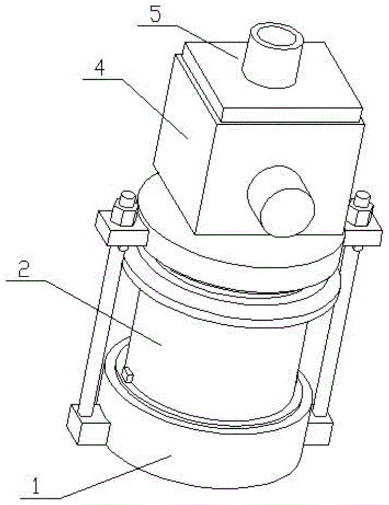
Figure 201810702771

The invention relates to the technical field of graphene production, in particular to a graphene dry state peeling device. An air pump introduces an air flow mixed with graphite dry powder raw materials into a gap, and the air flow replaces a traditional solvent to disperse the graphene. The transverse shearing is performed first and then the longitudinal shearing is performed, so that the probability of the graphite dry powder raw material being sheared and peeled off by the shearing edge without the aid of a solvent is greatly increased; The relative rotation speed of the vertical rotating column is made larger, and it is easier to cut the graphite sheet. The lower end of the middle cylinder assembly is rotatably connected to the upper end of the bottom assembly, the transverse shearing member is rotatably connected in the middle cylinder assembly, the lower end of the transverse shearing member is connected with the bottom assembly, and the upper end of the middle cylinder assembly is connected with the vertical shearing assembly. The lower end of the vertical shearing assembly is rotatably connected, the vertical shearing assembly is fixedly connected to the upper end of the bottom assembly, and the top cover assembly is fixedly connected to the upper end of the vertical shearing assembly.

Figure 201810702771

Description

Graphene dry-state stripping device
Technical Field
The invention relates to the technical field of graphene production, in particular to a graphene dry-state stripping device.
Background
Graphene is the thinnest and hardest nano material in the known world, has good electrical, optical and thermal properties, has excellent mechanical strength and flexibility, and can be used in the fields of composite materials, coatings, supercapacitors and the like.
The invention discloses a graphene dry-state stripping device with the application number of CN201510575311.5, discloses a graphene dry-state stripping device, a production system and a method for producing dry-state graphene, and relates to the technical field of graphene production. Be equipped with feed inlet and discharge gate on this stripping off device, its characterized in that, stripping off device includes outer barrel spare and the inner core spare of axis coincidence, relative rotation between outer barrel spare and the inner core spare, form the space that supplies the material to pass through between the inner wall of outer barrel spare and the outer wall of inner core spare, be equipped with the shearing arch on the inner wall in space, stripping off device is in the feed inlet is connected with the air-blast device or the discharge gate is connected with the induced air device, the air current of thoughtlessly having graphite dry powder raw materials by air-blast device or induced air device introduce feed inlet and space in proper order, flow out from the discharge gate after being sheared by the shearing arch of space department. The stripping device solves the problems of low production efficiency and low product quality of the conventional graphene stripping device. However, the method can only cut graphite transversely and cut graphite in multiple directions, so that graphene can be prepared better.
Disclosure of Invention
The invention provides a graphene dry-state stripping device which has the advantages that an air pump introduces air flow mixed with a graphite dry powder raw material into a gap, the graphene is dispersed by the air flow instead of a traditional solvent, and the graphite flake is firstly transversely sheared and then longitudinally sheared, so that the probability that the graphite dry powder raw material is sheared and stripped by a shearing blade without the help of the solvent is greatly improved; the middle cylinder and the vertical rotary column can rotate in opposite directions, so that the relative rotating speed of the vertical rotary column is higher, and the graphite flakes can be sheared more easily.
The invention relates to the technical field of graphene production, in particular to a graphene dry-state stripping device which comprises a bottom assembly, a middle barrel assembly, a transverse shearing piece, a vertical shearing assembly and a top cover assembly, wherein an air pump introduces air flow mixed with a graphite dry powder raw material into a gap, the air flow replaces a traditional solvent to disperse graphene, and a graphite sheet is firstly transversely sheared and then longitudinally sheared, so that the probability that the graphite dry powder raw material is sheared and stripped by a shearing blade without the help of the solvent is greatly improved; the middle cylinder and the vertical rotary column can rotate in opposite directions, so that the relative rotating speed of the vertical rotary column is higher, and the graphite flakes can be sheared more easily.
The lower extreme of well section of thick bamboo subassembly rotate to be connected in the upper end of bottom subassembly, horizontal shearing piece rotates to be connected in well section of thick bamboo subassembly, the lower extreme and the bottom subassembly of horizontal shearing piece are connected, the upper end of well section of thick bamboo subassembly rotates with the lower extreme of vertical shearing subassembly to be connected, vertical shearing subassembly fixed connection is in the upper end of bottom subassembly, top cap subassembly fixed connection is in the upper end of vertical shearing subassembly, well section of thick bamboo subassembly and vertical shearing subassembly pass through gear engagement transmission.
The bottom subassembly include bottom, the otic placode, erect the round bar, the spacer pin, the nut, motor I and feed inlet, the equal fixedly connected with otic placode in both ends about the outside of bottom, the round bar is erect to the equal fixedly connected with in upper end of two otic placodes, the lower extreme central point of bottom puts fixedly connected with motor I, motor I's output shaft passes the bottom surface of bottom, the lower extreme fixedly connected with feed inlet of bottom, the inside intercommunication of feed inlet and bottom, the equal fixedly connected with spacer pin in upper end of two perpendicular round bars, the upper end of two perpendicular round bars all has the nut through threaded connection, the nut is located the upper end of spacer pin.
Well section of thick bamboo subassembly include well section of thick bamboo, the lower bearing, protruding dog, the awl ring gear, the upper bearing, go up the orifice plate, lower orifice plate and right angle cutting edge I, well section of thick bamboo is cylindric structure, the upper end fixedly connected with upper orifice plate of well section of thick bamboo, the lower extreme fixedly connected with lower orifice plate of well section of thick bamboo, the inside of well section of thick bamboo has a plurality of right angle cutting edge I from last equipartition down, the cross section of right angle cutting edge I is right angle shape, the lower extreme outside cover of well section of thick bamboo has lower bearing, the equal fixedly connected with protruding dog in both ends about the well section of thick bamboo lower extreme, the upper end and two protruding dog laminating of lower bearing, the upper bearing has been cup jointed in the upper end outside of well section of thick bamboo, the upper end outside fixedly connected with awl ring gear of well section of.
Horizontal shearing piece include vertical rotary column, go up the step shaft, step shaft and right angle cutting edge II down, the outside of vertical rotary column has a plurality of right angle cutting edge II from last equipartition down, right angle cutting edge II's cross section is the right angle shape, step shaft and lower step shaft on the upper and lower both ends difference fixedly connected with of vertical rotary column, it is connected with last orifice plate and lower orifice plate rotation respectively through bearing and lower step shaft to go up the step shaft, vertical rotary column is located well section of thick bamboo, form clearance I between vertical rotary column and the well section of thick bamboo, a plurality of right angle cutting edge II and a plurality of right angle cutting edge I staggered arrangement, motor I's output shaft passes through the lower extreme of coupling joint at lower step shaft.
The vertical shearing assembly comprises a square box, a transverse rotating shaft, a transverse rotating column, a triangular cutting edge, arc-shaped surface convex blocks, a motor II, inserting plates, a top cover, a lower belt pulley, a gear rotating shaft, an upper belt pulley, a synchronous toothed belt and a bevel gear, wherein the upper shaft is inserted at the lower end of the top cover, the two inserting plates are respectively inserted at the upper ends of two vertical round rods, the lower ends of the two inserting plates are respectively attached to two limiting pins, the upper ends of the two inserting plates are respectively attached to two nuts, the upper end of the top cover is fixedly connected with the square box, the square box is communicated with the top cover, the arc-shaped surface convex blocks are fixedly connected to the left inner wall and the right inner wall of the square box, the opposite surfaces of the two arc-shaped surface convex blocks are arc-shaped surfaces, the transverse rotating shaft is rotatably connected to the front end and the rear end of the square box, horizontal rotary column is located inside the square box, horizontal rotary column has a plurality of triangle cutting edges from the past to the back equipartition, all form clearance II between horizontal rotary column and two arcwall face lugs, the rear end fixedly connected with of horizontal pivot goes up the belt pulley, the rear end fixedly connected with gear shaft of top cap, bevel gear's rear end fixedly connected with and the coaxial lower belt pulley of bevel gear, lower belt pulley and bevel gear all rotate to be connected in gear shaft, the tensioning is connected with synchronous profile of tooth area between lower belt pulley and the last belt pulley, bevel gear's lower extreme and the rear end meshing of awl tooth ring.
The top cap subassembly include top cap and discharge gate, the upper end fixedly connected with discharge gate of top cap, discharge gate and the inside intercommunication of square box, the upper end of discharge gate is provided with the aspiration pump.
The graphene dry-state stripping device has the beneficial effects that:
according to the graphene dry-state stripping device, the air flow mixed with the graphite dry powder raw material is introduced into the gap by the air suction pump, the traditional solvent is replaced by the air flow to disperse graphene, and the graphite flake is firstly transversely sheared and then longitudinally sheared, so that the probability that the graphite dry powder raw material is sheared and stripped by the shearing edge without the help of the solvent is greatly improved; the middle cylinder and the vertical rotary column can rotate in opposite directions, so that the relative rotating speed of the vertical rotary column is higher, and the graphite flakes can be sheared more easily.
Drawings
The invention is described in further detail below with reference to the accompanying drawings and specific embodiments.
Fig. 1 is a schematic view of an overall structure of a graphene dry-state stripping device according to the present invention;
fig. 2 is a schematic view of the overall structure of a graphene dry-state stripping device according to the present invention;
fig. 3 is a schematic cross-sectional structure view of a graphene dry-state peeling apparatus according to the present invention;
FIG. 4 is a first schematic structural view of a base assembly;
FIG. 5 is a second schematic structural view of the bottom assembly;
FIG. 6 is a first schematic structural view of the middle barrel assembly;
FIG. 7 is a second schematic structural view of the middle barrel assembly;
FIG. 8 is a schematic cross-sectional view of the middle barrel assembly;
FIG. 9 is a first schematic structural view of a transverse shearing member;
FIG. 10 is a second schematic structural view of a cross-cut member;
FIG. 11 is a first schematic view of a vertical shear assembly;
FIG. 12 is a second schematic structural view of a vertical shear assembly;
FIG. 13 is a cross-sectional structural schematic of a vertical shear assembly;
fig. 14 is a schematic structural view of the cap assembly.
In the figure: a bottom assembly 1; a bottom cover 1-1; 1-2 of ear plate; 1-3 of a vertical round rod; 1-4 of a limiting pin; 1-5 parts of a nut; motor I1-6; 1-7 parts of a feed inlet; a middle cylinder component 2; 2-1 of a middle cylinder; a lower bearing 2-2; 2-3 of a convex stop block; 2-4 parts of a conical gear ring; 2-5 of an upper bearing; 2-6 parts of an upper orifice plate; 2-7 parts of a lower pore plate; a right-angle cutting edge I2-8; a transverse shearing member 3; 3-1 of a vertical rotary column; an upper stepped shaft 3-2; 3-3 of a lower stepped shaft; a right-angle cutting edge II 3-4; a vertical shear assembly 4; 4-1 of a square box; a transverse rotating shaft 4-2; 4-3 of a transverse rotary column; 4-4 parts of triangular cutting edge; 4-5 of arc-shaped surface bumps; motor II 4-6; 4-7 of an inserting plate; 4-8 parts of a top cover; 4-9 parts of a lower belt pulley; 4-10 of a gear rotating shaft; 4-11 parts of upper belt wheel; 4-12 parts of a synchronous toothed belt; bevel gears 4-13; a cap assembly 5; 5-1 of a top cover; and a discharge port 5-2.
Detailed Description
The first embodiment is as follows:
the embodiment is described below with reference to fig. 1 to 14, the invention relates to the technical field of graphene production, and more specifically relates to a graphene dry-state stripping device, which comprises a bottom assembly 1, a middle cylinder assembly 2, a transverse shearing member 3, a vertical shearing assembly 4 and a top cover assembly 5, wherein an air suction pump introduces air flow mixed with a graphite dry powder raw material into a gap, the graphene is dispersed by the air flow instead of a traditional solvent, and a graphite sheet is firstly transversely sheared and then longitudinally sheared, so that the probability that the graphite dry powder raw material is sheared and stripped by a shearing blade without the aid of the solvent is greatly improved; in the invention, the middle cylinder 2-1 and the vertical rotary column 3-1 can rotate reversely, so that the relative rotating speed of the vertical rotary column 3-1 is higher, and the graphite sheets are easier to shear.
The lower extreme of well section of thick bamboo subassembly 2 rotate to be connected in the upper end of bottom subassembly 1, horizontal shearing piece 3 rotates to be connected in well section of thick bamboo subassembly 2, the lower extreme of horizontal shearing piece 3 is connected with bottom subassembly 1, the upper end of well section of thick bamboo subassembly 2 rotates with the lower extreme of vertical shearing subassembly 4 to be connected, vertical shearing subassembly 4 fixed connection is in the upper end of bottom subassembly 1, top cap subassembly 5 fixed connection is in the upper end of vertical shearing subassembly 4, well section of thick bamboo subassembly 2 and vertical shearing subassembly 4 pass through the gear engagement transmission.
The bottom component 1 comprises a bottom cover 1-1, lug plates 1-2, vertical round rods 1-3, limiting pins 1-4, nuts 1-5, a motor I1-6 and a feed inlet 1-7, the left and right ends of the outer side of the bottom cover 1-1 are fixedly connected with the lug plates 1-2, the upper ends of the two lug plates 1-2 are fixedly connected with the vertical round rods 1-3, the central position of the lower end of the bottom cover 1-1 is fixedly connected with a motor I1-6, an output shaft of the motor I1-6 penetrates through the bottom surface of the bottom cover 1-1, the lower end of the bottom cover 1-1 is fixedly connected with the feed inlet 1-7, the feed inlet 1-7 is communicated with the inside of the bottom cover 1-1, the upper ends of the two vertical round rods 1-3 are fixedly connected with the limiting pins 1-4, the upper ends of the two vertical round rods 1-3 are both connected with the nuts, the nut 1-5 is positioned at the upper end of the limit pin 1-4. When the graphite powder feeding device is used, graphite dry powder is fed from a feeding hole 1-7, and a motor I1-6 is started.
The middle cylinder component 2 comprises a middle cylinder 2-1, a lower bearing 2-2, a convex stop block 2-3, a conical gear ring 2-4, an upper bearing 2-5, an upper orifice plate 2-6, a lower orifice plate 2-7 and a right-angle cutting edge I2-8, wherein the middle cylinder 2-1 is of a cylindrical structure, the upper end of the middle cylinder 2-1 is fixedly connected with the upper orifice plate 2-6, the lower end of the middle cylinder 2-1 is fixedly connected with the lower orifice plate 2-7, a plurality of right-angle cutting edges I2-8 are uniformly distributed in the middle cylinder 2-1 from top to bottom, the cross section of the right-angle cutting edge I2-8 is of a right angle shape, the lower bearing 2-2 is sleeved outside the lower end of the middle cylinder 2-1, the convex stop blocks 2-3 are fixedly connected to the left and right ends of the lower end of the middle cylinder 2-1, the upper end of the lower bearing 2-, an upper bearing 2-5 is sleeved on the outer side of the upper end of the middle cylinder 2-1, a conical gear ring 2-4 is fixedly connected to the outer side of the upper end of the middle cylinder 2-1, the conical gear ring 2-4 is located at the lower end of the upper bearing 2-5, and the lower bearing 2-2 is inserted on the bottom cover 1-1. The middle cylinder 2-1 can rotate at the upper end of the bottom cover 1-1 through a lower bearing 2-2.
The transverse shearing part 3 comprises a vertical rotary column 3-1, an upper stepped shaft 3-2, a lower stepped shaft 3-3 and a right-angle cutting edge II3-4, wherein the outer side of the vertical rotary column 3-1 is uniformly provided with a plurality of right-angle cutting edges II3-4 from top to bottom, the cross section of each right-angle cutting edge II3-4 is right-angled, the upper end and the lower end of the vertical rotary column 3-1 are respectively and fixedly connected with the upper stepped shaft 3-2 and the lower stepped shaft 3-3, the upper stepped shaft 3-2 and the lower stepped shaft 3-3 are respectively and rotatably connected with an upper orifice plate 2-6 and a lower orifice plate 2-7 through bearings, the vertical rotary column 3-1 is positioned in a middle cylinder 2-1, a gap I is formed between the vertical rotary column 3-1 and the middle cylinder 2-1, the right-angle cutting edges II3-4 and the right-angle cutting edges I2-8 are arranged in a, the output shaft of the motor I1-6 is connected to the lower end of the lower stepped shaft 3-3 through a coupling. The motor I1-6 drives the lower stepped shaft 3-3 to rotate when rotating, the lower stepped shaft 3-3 drives the vertical rotary column 3-1 and the upper stepped shaft 3-2 to rotate when rotating, at the moment, the plurality of right-angle cutting edges II3-4 also rotate along with the rotation of the vertical rotary column 3-1, the graphite dry powder is introduced from the feed inlet 1-7 into a gap I formed between the vertical rotary column 3-1 and the middle barrel 2-1, and the plurality of right-angle cutting edges II3-4 rotating at high speed transversely shear the graphite dry powder.
The vertical shearing component 4 comprises a square box 4-1, a horizontal rotating shaft 4-2, a horizontal rotating column 4-3, a triangular cutting edge 4-4, an arc surface bump 4-5, a motor II4-6, an inserting plate 4-7, a top cover 4-8, a lower belt pulley 4-9, a gear rotating shaft 4-10, an upper belt pulley 4-11, a synchronous toothed belt 4-12 and a bevel gear 4-13, an upper bearing 2-5 is inserted at the lower end of the top cover 4-8, two inserting plates 4-7 are respectively inserted at the upper ends of two vertical round rods 1-3, the lower ends of the two inserting plates 4-7 are respectively attached with two limiting pins 1-4, the upper ends of the two inserting plates 4-7 are respectively attached with two nuts 1-5, the upper end of the top cover 4-8 is fixedly connected with the square box 4-1, the square box 4-1 is communicated with the top cover 4-8, the left inner wall and the right inner wall of the square box 4-1 are fixedly connected with arc-shaped surface convex blocks 4-5, the opposite surfaces of the two arc-shaped surface convex blocks 4-5 are arc-shaped surfaces, the transverse rotating shaft 4-2 is rotatably connected with the front end and the rear end of the square box 4-1, the front end of the square box 4-1 is fixedly connected with a motor II4-6, the output shaft of the motor II4-6 is connected with the front end of the transverse rotating shaft 4-2 through a coupler, the transverse rotating shaft 4-2 is fixedly connected with a transverse rotating column 4-3, the transverse rotating column 4-3 is positioned inside the square box 4-1, the transverse rotating column 4-3 is uniformly distributed with a plurality of triangular cutting edges 4-4 from the front to the rear, and a gap II is formed between the transverse rotating column, the rear end of the transverse rotating shaft 4-2 is fixedly connected with an upper belt pulley 4-11, the rear end of the top cover 4-8 is fixedly connected with a gear rotating shaft 4-10, the rear end of the bevel gear 4-13 is fixedly connected with a lower belt pulley 4-9 coaxial with the bevel gear 4-13, the lower belt pulley 4-9 and the bevel gear 4-13 are both rotatably connected to the gear rotating shaft 4-10, a synchronous toothed belt 4-12 is connected between the lower belt pulley 4-9 and the upper belt pulley 4-11 in a tensioning mode, and the lower end of the bevel gear 4-13 is meshed with the rear end of the bevel gear ring 2-4. When the motor II4-6 rotates, the transverse rotating shaft 4-2 and the transverse rotating column 4-3 are driven to rotate, the transverse rotating column 4-3 drives the triangular cutting edges 4-4 to rotate, the graphite dry powder which is transversely sheared by the right-angle cutting edges II3-4 enters the gap II, and the triangular cutting edges 4-4 rotate at a high speed to longitudinally shear the graphite dry powder again; the synchronous cog belt 4-12 rotates and simultaneously drives the upper belt pulley 4-11 to rotate, the upper belt pulley 4-11 drives the lower belt pulley 4-9 to rotate through the synchronous cog belt 4-12, the lower belt pulley 4-9 rotates and drives the bevel gear 4-13 to rotate, the bevel gear 4-13 is meshed with the bevel gear ring 2-4, and the bevel gear ring 2-4 drives the middle cylinder 2-1 to rotate in the direction opposite to the rotating direction of the vertical rotating column 3-1, so that the relative rotating speed of the vertical rotating column 3-1 is faster, and graphite flakes are easier to shear.
The top cover assembly 5 comprises a top cover 5-1 and a discharge port 5-2, the upper end of the top cover 5-1 is fixedly connected with the discharge port 5-2, the discharge port 5-2 is communicated with the interior of the square box 4-1, and the upper end of the discharge port 5-2 is provided with an air suction pump. And finally discharging the graphite dry powder subjected to transverse and longitudinal shearing from a discharge port 5-2. The function of the air pump is to make the graphite dry powder flow out along with the air flow.
The working principle of the invention is as follows: when the graphite powder feeding device is used, graphite dry powder is fed from a feeding hole 1-7, and a motor I1-6 is started. The middle cylinder 2-1 can rotate at the upper end of the bottom cover 1-1 through a lower bearing 2-2. The motor I1-6 drives the lower stepped shaft 3-3 to rotate when rotating, the lower stepped shaft 3-3 drives the vertical rotary column 3-1 and the upper stepped shaft 3-2 to rotate when rotating, at the moment, the plurality of right-angle cutting edges II3-4 also rotate along with the rotation of the vertical rotary column 3-1, the graphite dry powder is introduced from the feed inlet 1-7 into a gap I formed between the vertical rotary column 3-1 and the middle barrel 2-1, and the plurality of right-angle cutting edges II3-4 rotating at high speed transversely shear the graphite dry powder. When the motor II4-6 rotates, the transverse rotating shaft 4-2 and the transverse rotating column 4-3 are driven to rotate, the transverse rotating column 4-3 drives the triangular cutting edges 4-4 to rotate, the graphite dry powder which is transversely sheared by the right-angle cutting edges II3-4 enters the gap II, and the triangular cutting edges 4-4 rotate at a high speed to longitudinally shear the graphite dry powder again; the synchronous cog belt 4-12 rotates and simultaneously drives the upper belt pulley 4-11 to rotate, the upper belt pulley 4-11 drives the lower belt pulley 4-9 to rotate through the synchronous cog belt 4-12, the lower belt pulley 4-9 rotates and drives the bevel gear 4-13 to rotate, the bevel gear 4-13 is meshed with the bevel gear ring 2-4, and the bevel gear ring 2-4 drives the middle cylinder 2-1 to rotate in the direction opposite to the rotating direction of the vertical rotating column 3-1, so that the relative rotating speed of the vertical rotating column 3-1 is faster, and graphite flakes are easier to shear. And finally discharging the graphite dry powder subjected to transverse and longitudinal shearing from a discharge port 5-2. The function of the air pump is to make the graphite dry powder flow out along with the air flow.
It is to be understood that the above description is not intended to limit the present invention, and the present invention is not limited to the above examples, and that various changes, modifications, additions and substitutions which are within the spirit and scope of the present invention and which may be made by those skilled in the art are also within the scope of the present invention.

Claims (2)

1. The utility model provides a graphite alkene dry-state stripping off device, includes bottom subassembly (1), well section of thick bamboo subassembly (2), horizontal shearing piece (3), vertical shearing subassembly (4) and top cap subassembly (5), its characterized in that: the lower end of the middle cylinder assembly (2) is rotatably connected to the upper end of the bottom assembly (1), the transverse shearing piece (3) is rotatably connected into the middle cylinder assembly (2), the lower end of the transverse shearing piece (3) is connected with the bottom assembly (1), the upper end of the middle cylinder assembly (2) is rotatably connected with the lower end of the vertical shearing assembly (4), the vertical shearing assembly (4) is fixedly connected to the upper end of the bottom assembly (1), the top cover assembly (5) is fixedly connected to the upper end of the vertical shearing assembly (4), and the middle cylinder assembly (2) and the vertical shearing assembly (4) are in meshing transmission through gears;
the bottom assembly (1) comprises a bottom cover (1-1), lug plates (1-2), vertical round rods (1-3), limiting pins (1-4), nuts (1-5), motors I (1-6) and feed inlets (1-7), the left end and the right end of the outer side of the bottom cover (1-1) are fixedly connected with the lug plates (1-2), the upper ends of the two lug plates (1-2) are fixedly connected with the vertical round rods (1-3), the center of the lower end of the bottom cover (1-1) is fixedly connected with the motors I (1-6), output shafts of the motors I (1-6) penetrate through the bottom surface of the bottom cover (1-1), the lower end of the bottom cover (1-1) is fixedly connected with the feed inlets (1-7), and the feed inlets (1-7) are communicated with the interior of the bottom cover (1-1), the upper ends of the two vertical round rods (1-3) are fixedly connected with limiting pins (1-4), the upper ends of the two vertical round rods (1-3) are connected with nuts (1-5) through threads, and the nuts (1-5) are positioned at the upper ends of the limiting pins (1-4);
the middle cylinder component (2) comprises a middle cylinder (2-1), a lower bearing (2-2), a convex stop block (2-3), a conical gear ring (2-4), an upper bearing (2-5), an upper orifice plate (2-6), a lower orifice plate (2-7) and a right angle cutting edge I (2-8), the middle cylinder (2-1) is of a cylindrical structure, the upper end of the middle cylinder (2-1) is fixedly connected with the upper orifice plate (2-6), the lower end of the middle cylinder (2-1) is fixedly connected with the lower orifice plate (2-7), a plurality of right angle cutting edges I (2-8) are uniformly distributed in the middle cylinder (2-1) from top to bottom, the cross section of the right angle cutting edge I (2-8) is of a right angle shape, the lower bearing (2-2) is sleeved outside the lower end of the middle cylinder (2-1), the left end and the right end of the lower end of the middle cylinder (2-1) are both fixedly connected with the convex, the upper end of the lower bearing (2-2) is attached to the two convex stop blocks (2-3), the outer side of the upper end of the middle cylinder (2-1) is sleeved with the upper bearing (2-5), the outer side of the upper end of the middle cylinder (2-1) is fixedly connected with a conical gear ring (2-4), the conical gear ring (2-4) is positioned at the lower end of the upper bearing (2-5), and the lower bearing (2-2) is inserted into the bottom cover (1-1);
the transverse shearing part (3) comprises a vertical rotary column (3-1), an upper stepped shaft (3-2), a lower stepped shaft (3-3) and right-angle cutting edges II (3-4), a plurality of right-angle cutting edges II (3-4) are uniformly distributed on the outer side of the vertical rotary column (3-1) from top to bottom, the cross section of the right-angle cutting edges II (3-4) is right-angled, the upper and lower ends of the vertical rotary column (3-1) are respectively and fixedly connected with the upper stepped shaft (3-2) and the lower stepped shaft (3-3), the upper stepped shaft (3-2) and the lower stepped shaft (3-3) are respectively and rotatably connected with an upper pore plate (2-6) and a lower pore plate (2-7) through bearings, the vertical rotary column (3-1) is positioned in a middle barrel (2-1), a gap I is formed between the vertical rotary column (3-1) and the middle barrel (2-1), the plurality of right-angle cutting edges II (3-4) and the plurality of right-angle cutting edges I (2-8) are arranged in a staggered mode, and output shafts of the motors I (1-6) are connected to the lower end of the lower stepped shaft (3-3) through couplers;
the vertical shearing assembly (4) comprises a square box (4-1), a horizontal rotating shaft (4-2), a horizontal rotating column (4-3), a triangular cutting edge (4-4), an arc surface bump (4-5), a motor II (4-6), inserting plates (4-7), a top cover (4-8), a lower belt pulley (4-9), a gear rotating shaft (4-10), an upper belt pulley (4-11), a synchronous toothed belt (4-12) and a bevel gear (4-13), wherein an upper bearing (2-5) is inserted at the lower end of the top cover (4-8), two inserting plates (4-7) are respectively inserted at the upper ends of the two vertical round rods (1-3), the lower ends of the two inserting plates (4-7) are respectively attached to the two limiting pins (1-4), the upper ends of the two inserting plates (4-7) are respectively attached to the two nuts (1-5), the upper end of the top cover (4-8) is fixedly connected with a square box (4-1), the square box (4-1) is communicated with the top cover (4-8), the left inner wall and the right inner wall of the square box (4-1) are fixedly connected with arc-shaped surface convex blocks (4-5), the opposite surfaces of the two arc-shaped surface convex blocks (4-5) are arc-shaped surfaces, a transverse rotating shaft (4-2) is rotatably connected with the front end and the rear end of the square box (4-1), the front end of the square box (4-1) is fixedly connected with a motor II (4-6), the output shaft of the motor II (4-6) is connected with the front end of the transverse rotating shaft (4-2) through a coupler, the transverse rotating column (4-3) is fixedly connected with the transverse rotating shaft (4-2), and the transverse rotating column (4-3) is positioned inside the, a plurality of triangular cutting edges (4-4) are uniformly distributed on the transverse rotary column (4-3) from front to back, a gap II is formed between the transverse rotary column (4-3) and the two arc-shaped surface convex blocks (4-5), an upper belt pulley (4-11) is fixedly connected with the rear end of the transverse rotary shaft (4-2), a gear rotary shaft (4-10) is fixedly connected with the rear end of the top cover (4-8), a lower belt pulley (4-9) coaxial with the bevel gear (4-13) is fixedly connected with the rear end of the bevel gear (4-13), the lower belt pulley (4-9) and the bevel gear (4-13) are rotatably connected onto the gear rotary shaft (4-10), a synchronous toothed belt (4-12) is connected between the lower belt pulley (4-9) and the upper belt pulley (4-11) in a tensioning mode, and the lower end of the bevel gear (4-13) is meshed with the rear end of the conical toothed ring (.
2. The graphene dry-state peeling device according to claim 1, characterized in that: the top cover assembly (5) comprises a top cover (5-1) and a discharge port (5-2), the upper end of the top cover (5-1) is fixedly connected with the discharge port (5-2), the discharge port (5-2) is communicated with the interior of the square box (4-1), and the upper end of the discharge port (5-2) is provided with an air suction pump.
CN201810702771.3A 2018-06-30 2018-06-30 Graphene dry-state stripping device Active CN108855479B (en)

Priority Applications (1)

Application Number Priority Date Filing Date Title
CN201810702771.3A CN108855479B (en) 2018-06-30 2018-06-30 Graphene dry-state stripping device

Applications Claiming Priority (1)

Application Number Priority Date Filing Date Title
CN201810702771.3A CN108855479B (en) 2018-06-30 2018-06-30 Graphene dry-state stripping device

Publications (2)

Publication Number Publication Date
CN108855479A CN108855479A (en) 2018-11-23
CN108855479B true CN108855479B (en) 2020-04-10

Family

ID=64297630

Family Applications (1)

Application Number Title Priority Date Filing Date
CN201810702771.3A Active CN108855479B (en) 2018-06-30 2018-06-30 Graphene dry-state stripping device

Country Status (1)

Country Link
CN (1) CN108855479B (en)

Families Citing this family (3)

* Cited by examiner, † Cited by third party
Publication number Priority date Publication date Assignee Title
CN112439527B (en) * 2020-10-20 2021-10-26 山东华冠智能卡有限公司 Graphene stripping device
CN112337614B (en) * 2020-10-20 2022-03-29 山东华冠智能卡有限公司 Graphite alkene master batch grinds stripping off device
CN115921048B (en) * 2022-12-21 2025-11-21 上饶市康然光学仪器有限公司 Graphite shearing device and shearing method

Citations (9)

* Cited by examiner, † Cited by third party
Publication number Priority date Publication date Assignee Title
CN203355825U (en) * 2013-06-06 2013-12-25 广东美味鲜调味食品有限公司 Wet feed pulverizer
CN105363535A (en) * 2015-09-10 2016-03-02 江阴碳谷科技有限公司 Dry graphene stripping device, production system and method for producing dry graphene
CN205700910U (en) * 2016-04-27 2016-11-23 伊犁职业技术学院 A kind of chemical industry multistage rotating cylinder mechanical crusher
CN206273340U (en) * 2016-12-14 2017-06-23 浙江海洋大学 A kind of rabbling mechanism of chemical fertilizer mixer
CN107224953A (en) * 2017-06-08 2017-10-03 浙江康牧药业有限公司 Florfenicol is produced with to stirring the feed type reactor that is scattered
CN206661357U (en) * 2017-04-05 2017-11-24 重庆中加沥青技术服务有限公司 A kind of polymer modified asphalt high-speed shearing machine
CN207102498U (en) * 2017-06-29 2018-03-16 东台市天源荧光材料有限公司 A kind of powdery paints machine
CN108160251A (en) * 2017-12-28 2018-06-15 郑州格瑞塔电子信息技术有限公司 A kind of vertical potato differential breaker
CN108187860A (en) * 2018-03-07 2018-06-22 鲍孟波 A kind of attrition grinding equipment of Chinese medicine

Patent Citations (9)

* Cited by examiner, † Cited by third party
Publication number Priority date Publication date Assignee Title
CN203355825U (en) * 2013-06-06 2013-12-25 广东美味鲜调味食品有限公司 Wet feed pulverizer
CN105363535A (en) * 2015-09-10 2016-03-02 江阴碳谷科技有限公司 Dry graphene stripping device, production system and method for producing dry graphene
CN205700910U (en) * 2016-04-27 2016-11-23 伊犁职业技术学院 A kind of chemical industry multistage rotating cylinder mechanical crusher
CN206273340U (en) * 2016-12-14 2017-06-23 浙江海洋大学 A kind of rabbling mechanism of chemical fertilizer mixer
CN206661357U (en) * 2017-04-05 2017-11-24 重庆中加沥青技术服务有限公司 A kind of polymer modified asphalt high-speed shearing machine
CN107224953A (en) * 2017-06-08 2017-10-03 浙江康牧药业有限公司 Florfenicol is produced with to stirring the feed type reactor that is scattered
CN207102498U (en) * 2017-06-29 2018-03-16 东台市天源荧光材料有限公司 A kind of powdery paints machine
CN108160251A (en) * 2017-12-28 2018-06-15 郑州格瑞塔电子信息技术有限公司 A kind of vertical potato differential breaker
CN108187860A (en) * 2018-03-07 2018-06-22 鲍孟波 A kind of attrition grinding equipment of Chinese medicine

Also Published As

Publication number Publication date
CN108855479A (en) 2018-11-23

Similar Documents

Publication Publication Date Title
CN108855479A (en) A kind of graphene dry state stripping off device
US7425090B2 (en) Device for dispersing and melting flowable materials
WO2017215598A1 (en) New continuous mixer structure
CN103935013A (en) Four-screw mixing extruder
CN204019951U (en) Extruder screw
DE2513577B2 (en) Continuously working mixer for plastic materials
CN207161626U (en) It is a kind of can full angle rotation conical double-screw gear-box
CN104228037B (en) Three screw rod banded extruders
CN214354063U (en) A extruding machine feed arrangement for plastic pellet production
CN213767096U (en) A high-efficient single screw extruder for plastics processing
CN104690954A (en) Treatment machine for increasing surface roughness of plastic foam particles
CN103057083B (en) High polymer material eccentricity spiral stirring type compulsory feeding method and device thereof
CN103978574B (en) A kind of screw device for discharging being applied to banbury
CN210448956U (en) Premixing mechanism before powder coating is extruded
CN202022400U (en) A kind of constant feeder for granulator
CN222039239U (en) Single screw squeezing machine
CN219486518U (en) Stabilized twin-screw extruder
CN212092149U (en) Transmission shaft system of continuous screw granulator
CN220428918U (en) Combined rubber-plastic machine
CN203031905U (en) Eccentric spiral stirring forced feeding device for high polymer materials
CN224100850U (en) An extrusion and tearing device for producing reed fluff
CN223211880U (en) Double-screw structure of pre-dispersion masterbatch extruder
CN221816047U (en) Particle forming machine
CN104149305A (en) Efficient mixing extruder with screw rod distributed annularly in different directions
CN223818575U (en) Twin-tapered screw extrusion unit and extruder

Legal Events

Date Code Title Description
PB01 Publication
PB01 Publication
SE01 Entry into force of request for substantive examination
TA01 Transfer of patent application right

Effective date of registration: 20200313

Address after: Room a526, 418 Xinhua West Road, Dachang street, Jiangbei new district, Nanjing City, Jiangsu Province

Applicant after: Nanjing langchen Equipment Technology Co.,Ltd.

Address before: 253000 No. 17, Nan Yang village, Zhao Hu Town, Decheng District, Dezhou, Shandong

Applicant before: Liu Qingkai

GR01 Patent grant
GR01 Patent grant
CP03 Change of name, title or address

Address after: 266000 1403-228, block B, No. 1, Keyuan Weiyi Road, Innovation Park Phase I, Laoshan District, Qingdao, Shandong

Patentee after: Qingdao Zhongtian Kejie Industrial Technology Co.,Ltd.

Address before: Room a526, No. 418, Xinhua West Road, Dachang street, Jiangbei new district, Nanjing, Jiangsu 210000

Patentee before: Nanjing langchen Equipment Technology Co.,Ltd.

TR01 Transfer of patent right

Effective date of registration: 20250325

Address after: 266000 Wangyanzhuang Road, Luanbu Village, Lancun Street, Jimo District, Qingdao City, Shandong Province

Patentee after: QINGDAO CHENGXUAN NEW MATERIAL MANUFACTURING CO.,LTD.

Country or region after: China

Address before: 266000 1403-228, block B, No. 1, Keyuan Weiyi Road, Innovation Park Phase I, Laoshan District, Qingdao, Shandong

Patentee before: Qingdao Zhongtian Kejie Industrial Technology Co.,Ltd.

Country or region before: China