CN108842542B - Full-section grinding operation vehicle for rail weld seam and using method thereof - Google Patents
Full-section grinding operation vehicle for rail weld seam and using method thereof Download PDFInfo
- Publication number
- CN108842542B CN108842542B CN201810902082.7A CN201810902082A CN108842542B CN 108842542 B CN108842542 B CN 108842542B CN 201810902082 A CN201810902082 A CN 201810902082A CN 108842542 B CN108842542 B CN 108842542B
- Authority
- CN
- China
- Prior art keywords
- rail
- polishing
- steel rail
- grinding
- sliding table
- Prior art date
- Legal status (The legal status is an assumption and is not a legal conclusion. Google has not performed a legal analysis and makes no representation as to the accuracy of the status listed.)
- Active
Links
Images






Classifications
-
- E—FIXED CONSTRUCTIONS
- E01—CONSTRUCTION OF ROADS, RAILWAYS, OR BRIDGES
- E01B—PERMANENT WAY; PERMANENT-WAY TOOLS; MACHINES FOR MAKING RAILWAYS OF ALL KINDS
- E01B31/00—Working rails, sleepers, baseplates, or the like, in or on the line; Machines, tools, or auxiliary devices specially designed therefor
- E01B31/02—Working rail or other metal track components on the spot
- E01B31/12—Removing metal from rails, rail joints, or baseplates, e.g. for deburring welds, reconditioning worn rails
- E01B31/17—Removing metal from rails, rail joints, or baseplates, e.g. for deburring welds, reconditioning worn rails by grinding
-
- Y—GENERAL TAGGING OF NEW TECHNOLOGICAL DEVELOPMENTS; GENERAL TAGGING OF CROSS-SECTIONAL TECHNOLOGIES SPANNING OVER SEVERAL SECTIONS OF THE IPC; TECHNICAL SUBJECTS COVERED BY FORMER USPC CROSS-REFERENCE ART COLLECTIONS [XRACs] AND DIGESTS
- Y02—TECHNOLOGIES OR APPLICATIONS FOR MITIGATION OR ADAPTATION AGAINST CLIMATE CHANGE
- Y02P—CLIMATE CHANGE MITIGATION TECHNOLOGIES IN THE PRODUCTION OR PROCESSING OF GOODS
- Y02P70/00—Climate change mitigation technologies in the production process for final industrial or consumer products
- Y02P70/10—Greenhouse gas [GHG] capture, material saving, heat recovery or other energy efficient measures, e.g. motor control, characterised by manufacturing processes, e.g. for rolling metal or metal working
Landscapes
- Engineering & Computer Science (AREA)
- Mechanical Engineering (AREA)
- Architecture (AREA)
- Civil Engineering (AREA)
- Structural Engineering (AREA)
- Machines For Laying And Maintaining Railways (AREA)
Abstract
本发明涉及轨道工程技术领域,具体来说是一种钢轨焊缝全断面打磨作业车及其使用方法,车架体中部为作业区段,作业区段处设有打磨装置,作业区段两侧为支撑区段,支撑区段处设有钢轨提升装置、支腿系统及轮组系统,支撑区段外侧为辅助区段,辅助区段处及所述的支撑区段处相对应设有钢轨定位装置。本发明同现有技术相比,其优点在于:将打磨焊缝各部位的设备整合形成一套打磨系统,集成度高,便于操作;每个磨头装置采用两套燕尾槽结构与作业平台连接,可更加精准调节磨头打磨状态;设有钢轨提升装置,以及轮组起落式设计,可自行提升钢轨;保证钢轨位置精确牢固,确保打磨效果;钢轨定位装置夹点采用倒三点可调式布置,便于对钢轨位置进行微调。
The invention relates to the technical field of track engineering, in particular to a full-section grinding operation vehicle for rail welds and a method for using the same. It is a support section, and the support section is equipped with a rail lifting device, outrigger system and wheel system. The outside of the support section is an auxiliary section, and the auxiliary section and the support section are equipped with rail positioning. device. Compared with the prior art, the present invention has the advantages that: the equipment for grinding each part of the weld seam is integrated to form a grinding system, which has a high degree of integration and is easy to operate; each grinding head device adopts two sets of dovetail groove structures to connect with the working platform , can more accurately adjust the grinding state of the grinding head; equipped with a rail lifting device, and a wheel set lifting design, which can lift the rail by itself; ensure that the position of the rail is accurate and firm, and ensure the grinding effect; the clamp point of the rail positioning device adopts an inverted three-point adjustable arrangement , to facilitate fine-tuning of the rail position.
Description
技术领域technical field
本发明涉及轨道工程技术领域,具体来说是一种钢轨焊缝全断面打磨作业车及其使用方法。The invention relates to the technical field of rail engineering, in particular to a full-section grinding operation vehicle for rail weld seams and a method for using the same.
背景技术Background technique
目前国内城市轨道无缝线路施工仍采用人工手持砂轮机或仿形砂轮机进行焊缝打磨作业,这类设备均不是专用钢轨作业设备,作业时需要其他辅助手段,例如:配置发电机、人工起升钢轨等,其劳动强度大,工效低,打磨效果受作业人员操作影响,打磨质量不稳定,检测手段仍然是采用原始的直靠尺,通过肉眼观察和塞尺测量来实现,精度差,设备整合程度低,已不能满足快速施工的作业需求。国内铁路运营线路打磨采用的是打磨列车进行作业,虽然工作效率高,但设备体积庞大、价格昂贵,而且只能对轨头进行打磨,并不适合进行地铁隧道内无缝线路施工作业。At present, the construction of domestic urban rail seamless lines still uses manual hand-held grinders or profiling grinders for weld grinding operations. These types of equipment are not special equipment for rail operations, and other auxiliary means are required for operations, such as: configuration of generators, manual Lifting rails, etc., have high labor intensity and low work efficiency. The grinding effect is affected by the operation of the operator, and the grinding quality is unstable. The detection method is still the original straight ruler, which is realized by visual observation and feeler gauge measurement. The low degree of equipment integration can no longer meet the needs of rapid construction operations. Domestic railway operation lines are polished by grinding trains. Although the work efficiency is high, the equipment is bulky and expensive, and can only polish the rail head, which is not suitable for seamless line construction in subway tunnels.
发明内容Contents of the invention
本发明的目的在于解决现有技术的不足,提供一种钢轨焊缝全断面打磨作业车及其使用方法,包括钢轨焊缝全断面自动打磨、自动检测机构,以及配套钢轨提升、钢轨夹持定位系统,走行、支撑和其他辅助系统在内的一体化打磨作业车,以实现在建线路钢轨焊缝自动化打磨作业。The purpose of the present invention is to solve the deficiencies of the prior art, to provide a rail weld full-section grinding operation vehicle and its use method, including rail weld full-section automatic grinding, automatic detection mechanism, and supporting rail lifting, rail clamping and positioning system, an integrated grinding operation vehicle including running, supporting and other auxiliary systems, to realize automatic grinding of rail welds on lines under construction.
为了实现上述目的,设计一种钢轨焊缝全断面打磨作业车,所述的打磨作业车包括车架体,所述的车架体中部为作业区段,所述的作业区段处设有打磨装置,所述的作业区段两侧为支撑区段,所述的支撑区段处设有钢轨提升装置、支腿系统及轮组系统,所述的支撑区段外侧为辅助区段,所述的辅助区段处及所述的支撑区段处相对应设有钢轨定位装置。In order to achieve the above purpose, a full-section grinding operation vehicle for rail welds is designed. The grinding operation vehicle includes a frame body, the middle part of the frame body is a working section, and a grinding device, the two sides of the working section are supporting sections, and the supporting section is equipped with a rail lifting device, outrigger system and wheel system, and the outside of the supporting section is an auxiliary section. A rail positioning device is correspondingly provided at the auxiliary section and the support section.
所述的打磨装置包括作业平台、轨头打磨装置、轨腰打磨装置、轨底打磨装置及平台驱动装置,所述的作业平台包括两块平行设置的立板,两块立板底端通过两块平行设置的底板相连且所述的底板之间设有间隙,所述的立板底端对应于间隙处设有凹槽豁口,用于供钢轨放置,所述的底板底部设有滑动导轨,用于与所述的车架体上设有的槽道相配合并在平台驱动装置的驱动下使打磨装置沿所述的车架体上设有的槽道移动,在所述的立板上环绕所述的凹槽豁口设有若干钢轨线性检测探头,用于对钢轨的顶面及两侧面进行线性检测。The grinding device includes a working platform, a rail head grinding device, a rail waist grinding device, a rail bottom grinding device and a platform driving device. The working platform includes two parallel vertical plates, and the bottom ends of the two vertical plates pass through two The bottom plates arranged in parallel are connected and there is a gap between the bottom plates. The bottom end of the vertical plate is provided with a groove gap corresponding to the gap for placing the rails. The bottom of the bottom plate is provided with a sliding guide rail. It is used to cooperate with the channel provided on the frame body and make the grinding device move along the channel provided on the frame body under the drive of the platform driving device, and circle around the vertical plate The notch of the groove is provided with a plurality of rail linear detection probes, which are used for linear detection of the top surface and both sides of the rail.
在间隙两侧交错布置有至少两组轨头打磨装置,所述的轨头打磨装置的磨头电机采用卧式布置,每组所述的轨头打磨装置的相对一侧设有轨腰打磨装置,所述的轨腰打磨装置的磨头电机采用立式布置,在立板的外侧设有轨底打磨装置,所述的轨底打磨装置的磨头电机采用卧式布置。There are at least two groups of rail head grinding devices staggered on both sides of the gap, the grinding head motors of the rail head grinding devices are arranged horizontally, and a rail waist grinding device is provided on the opposite side of each group of rail head grinding devices , the grinding head motor of the rail waist grinding device adopts a vertical arrangement, and a rail bottom grinding device is arranged outside the vertical plate, and the grinding head motor of the rail bottom grinding device adopts a horizontal arrangement.
所述的平台驱动装置包括通过电机座固定在作业平台外的驱动电机,驱动电机的输出端连接有驱动丝杠,所述的驱动丝杠穿过若干丝杠座,所述的丝杠座固定在所述的作业平台顶部。The platform driving device includes a drive motor fixed outside the work platform through a motor base, the output end of the drive motor is connected with a drive screw, and the drive screw passes through several screw seats, and the screw seat is fixed on the top of the working platform.
所述的轮组系统包括主动轮组和从动轮组,所述的主动轮组包括轮组支腿,所述的轮组支腿上开设有安装孔,用于实现与车体的转动连接,所述的轮组支腿顶端连接起落液压缸的一端,起落液压缸的另一端固定于车体上,所述的轮组支腿一侧设有驱动电机,所述的轮组支腿底端设有车轮总成,所述的驱动电机和车轮总成之间通过传动齿轮组实现传动,所述的传动齿轮组包括一高速级大齿轮,所述的高速级大齿轮与拨叉卡盘相连,所述的拨叉卡盘一端与拨叉杆相连,所述的拨叉杆与所述的轮组支腿相连,且所述的拨叉杆能沿拨叉杆的轴线方向移动,通过推拉所述的拨叉杆,能够使得所述的拨叉卡盘与高速级大齿轮同步移动,从而改变传动齿轮组的啮合状况。The wheel set system includes a driving wheel set and a driven wheel set, the driving wheel set includes a wheel set leg, and the wheel set leg is provided with a mounting hole for realizing a rotational connection with the vehicle body, The top of the wheel set leg is connected to one end of the lifting hydraulic cylinder, and the other end of the lifting hydraulic cylinder is fixed on the vehicle body. A drive motor is provided on one side of the wheel set leg, and the bottom end of the wheel set leg A wheel assembly is provided, and the transmission between the drive motor and the wheel assembly is realized through a transmission gear set. The transmission gear set includes a high-speed large gear, and the high-speed large gear is connected with the fork chuck , one end of the fork chuck is connected with the fork rod, the fork rod is connected with the wheel leg, and the fork rod can move along the axis direction of the fork rod, by pushing and pulling The shift fork lever can make the shift fork chuck move synchronously with the high-speed large gear, thereby changing the meshing condition of the transmission gear set.
所述的从动轮组包括轮组支腿,所述的轮组支腿上开设有安装孔,用于实现与车体的转动连接,所述的轮组支腿顶端连接起落液压缸的一端,起落液压缸的另一端固定于车体上,所述的轮组支腿的底端设有轮组总成。The driven wheel set includes a wheel set leg, and the wheel set leg is provided with a mounting hole for realizing the rotational connection with the vehicle body, and the top end of the wheel set leg is connected to one end of the lifting hydraulic cylinder, The other end of the lifting hydraulic cylinder is fixed on the car body, and the bottom end of the wheel set leg is provided with a wheel set assembly.
所述的钢轨定位装置包括定位箱,所述的定位箱一端的两侧及底部对应设有开口,用于容纳所述的钢轨,且所述的定位箱一端向定位箱内侧设有固定夹头,所述的定位箱另一端设有活动夹头,所述的活动夹头能在移动装置的作用下向固定夹头方向正向和反向运动,以实现对钢轨的夹持和松开,所述的活动夹头和所述的固定夹头的夹持工作面的下端面与所述的钢轨轨底的上表面相吻合,且所述的活动夹头和所述的固定夹头的夹持工作面的下端面下侧相对设有调节螺栓,所述的固定箱的一端对应于固定夹头的位置设有调节螺栓,所述的活动夹头上也相对设有若干调节螺栓,所述的调节螺栓的端部设有半球形结构以作为夹持支点,用于对钢轨进行夹持,在夹持座两侧的开口外侧还设有摆动卡钳,所述的摆动卡钳的一端为活动端,另一端与所述的固定箱转动相连,且所述的摆动卡钳的另一端上还设有滑槽及一端与滑槽相配合的连杆,连杆的另一端与所述的活动夹头固定相连,当所述的活动夹头运动时,能通过连杆带动所述的摆动卡钳的活动端转动,以使所述的活动端与固定箱的一端相连接或分离。The rail positioning device includes a positioning box, the two sides and the bottom of one end of the positioning box are correspondingly provided with openings for accommodating the rail, and one end of the positioning box is provided with a fixed chuck to the inside of the positioning box , the other end of the positioning box is provided with a movable chuck, and the movable chuck can move forward and reverse to the direction of the fixed chuck under the action of the moving device, so as to realize the clamping and loosening of the rail, The lower end surface of the clamping surface of the movable chuck and the fixed chuck coincides with the upper surface of the rail bottom, and the clamps of the movable chuck and the fixed chuck The lower side of the lower end of the holding surface is provided with adjusting bolts, one end of the fixed box is provided with adjusting bolts corresponding to the position of the fixed chuck, and the movable chuck is also provided with a number of adjusting bolts. The end of the adjusting bolt is provided with a hemispherical structure as a clamping fulcrum for clamping the rail. There are also swing calipers outside the openings on both sides of the clamping seat. One end of the swing calipers is a movable end. , the other end is rotatably connected with the fixed box, and the other end of the swing caliper is also provided with a chute and a connecting rod with one end matching the chute, and the other end of the connecting rod is connected with the movable chuck Fixedly connected, when the movable chuck moves, the movable end of the swing caliper can be driven to rotate through the connecting rod, so that the movable end is connected or separated from one end of the fixed box.
所述的车架体的四角设有支撑液压缸,在作业时支撑在地面或侧壁上。The four corners of the frame body are provided with supporting hydraulic cylinders, which are supported on the ground or side walls during operation.
所述的轨头打磨装置包括打磨滑台、磨头电机、轨头磨头和磨头座,所述的打磨滑台包括一套水平布置的滑台和一套竖直布置的滑台,以实现打磨滑台的二维移动,所述的打磨滑台靠近间隙一侧设有磨头座及轨头磨头,且所述的打磨滑台上设有用于驱动轨头磨头的磨头电机,所述的轨头磨头采用卧式布置。The rail head grinding device includes a grinding slide table, a grinding head motor, a rail head grinding head and a grinding head seat, and the described grinding slide table includes a set of horizontally arranged slide tables and a set of vertically arranged slide tables, so as to Realize the two-dimensional movement of the grinding slide table, the side of the grinding slide table close to the gap is provided with a grinding head seat and a rail head grinding head, and the grinding slide table is provided with a grinding head motor for driving the rail head grinding head , the rail head grinding head is arranged horizontally.
所述的轨腰打磨装置包括打磨滑台、磨头电机、轨腰磨头和磨头座,所述的打磨滑台包括一套水平布置的滑台和一套竖直布置的滑台,以实现打磨滑台的二维移动,所述的打磨滑台靠近间隙一侧设有磨头座及轨腰磨头,且所述的打磨滑台上设有用于驱动轨腰磨头的磨头电机,所述的轨腰磨头采用立式布置。The rail waist grinding device includes a grinding slide table, a grinding head motor, a rail waist grinding head and a grinding head seat, and the grinding slide table includes a set of horizontally arranged slide tables and a set of vertically arranged slide tables, so as to Realize the two-dimensional movement of the grinding slide table, the side of the grinding slide table close to the gap is provided with a grinding head seat and a rail waist grinding head, and the grinding slide table is provided with a grinding head motor for driving the rail waist grinding head , the rail waist grinding head adopts vertical arrangement.
所述的轨底打磨装置包括打磨滑台、磨头电机、轨底磨头和磨头座,所述的打磨滑台包括一套水平布置的滑台和一套竖直布置的滑台,以实现打磨滑台的二维移动,所述的打磨滑台靠近间隙一侧设有磨头座及轨底磨头,且所述的打磨滑台上设有用于驱动轨底磨头的磨头电机,所述的轨底磨头采用立式布置。The rail bottom grinding device includes a grinding slide table, a grinding head motor, a rail bottom grinding head and a grinding head seat, and the grinding slide table includes a set of horizontally arranged slide tables and a set of vertically arranged slide tables for Realize the two-dimensional movement of the grinding slide table, the side of the grinding slide table close to the gap is provided with a grinding head seat and a rail bottom grinding head, and the grinding slide table is provided with a grinding head motor for driving the rail bottom grinding head , the rail bottom grinding head adopts vertical arrangement.
所述的滑台由滑台驱动电机驱动,所述的滑台驱动电机通过传动齿轮带动与滑台相连的滑台丝杠运动以实现驱动,所述的传动齿轮通过花键与所述的滑台驱动电机的输出轴相啮合,所述的传动齿轮与拨叉固定相连,通过转动所述的拨叉能改变所述的传动齿轮与滑台驱动电机的输出轴之间的啮合状态,所述的滑台丝杠的外端还设有手动摇柄。The slide table is driven by a slide table drive motor, and the slide table drive motor drives the slide table lead screw connected with the slide table to move through the transmission gear, and the transmission gear is connected to the slide table through a spline. The output shaft of the table drive motor is meshed, and the transmission gear is fixedly connected with the shift fork. By turning the shift fork, the meshing state between the transmission gear and the output shaft of the slide table drive motor can be changed. The outer end of the sliding table screw is also provided with a manual crank handle.
所述的轮组支腿由平行设置的第一支腿结构和第二支腿结构构成,所述的第一支腿结构和第二支腿结构由上至下相对应地依次设有四组安装孔,第一组安装孔之间连接有销轴,所述的销轴用于与起落液压缸的一端固定相连,第二组安装孔用于与车体轴连接以实现与车体的转动连接,第三组安装孔用于连接离合拨叉杆,第四组安装孔用于连接车轮总成。The wheel set leg is composed of a first leg structure and a second leg structure arranged in parallel, and the first leg structure and the second leg structure are sequentially arranged in four groups correspondingly from top to bottom Mounting holes, the first set of mounting holes is connected with a pin shaft, the pin shaft is used to be fixedly connected with one end of the lifting hydraulic cylinder, and the second set of mounting holes is used to connect with the vehicle body shaft to realize the rotation with the vehicle body connection, the third set of mounting holes is used to connect the clutch shift fork lever, and the fourth set of mounting holes is used to connect the wheel assembly.
所述的第三组安装孔内设有离合拨叉固定座,所述的离合拨叉杆穿过所述的离合拨叉固定座,位于离合拨叉固定座之间的离合拨叉杆外侧套设有离合拨叉限位块,所述的离合拨叉固定座的一侧向离合拨叉杆的轴向方向设有延伸段,所述的延伸段上设有开孔,所述的离合拨叉杆对应于所述的开孔的方向也设有若干通孔,所述的通孔和开孔用于供开口销穿过,以实现对离合拨叉杆的固定。所述的拨叉杆的一端设有拨叉把手。The third group of mounting holes is provided with clutch shift fork fixing seats, the clutch shift fork rod passes through the clutch shift fork fixing seats, and the outer sleeve of the clutch shift fork rod located between the clutch shift fork fixing seats A clutch shift fork limit block is provided, and one side of the clutch shift fork fixing base is provided with an extension section in the axial direction of the clutch shift fork rod, and an opening is provided on the extension section, and the clutch shifter The fork lever is also provided with several through holes corresponding to the direction of the opening, and the through holes and openings are used for passing through the cotter pin to realize the fixing of the clutch shift fork lever. One end of the fork lever is provided with a fork handle.
所述的钢轨提升装置对应于所述的钢轨定位装置而设置,用于将钢轨提升至钢轨定位装置的开口处,所述的钢轨提升装置包括提升液压缸,所述的提升液压缸下端依次连接有连接杆和钢轨夹具,所述的车架体在对应于所述的钢轨提升装置处设有限位套,所述的连接杆能竖直穿过所述的限位套,以实现对连接杆在水平方向的约束。The rail lifting device is arranged corresponding to the rail positioning device, and is used to lift the rail to the opening of the rail positioning device. The rail lifting device includes a lifting hydraulic cylinder, and the lower ends of the lifting hydraulic cylinders are sequentially connected to There are connecting rods and rail clamps, and the frame body is provided with a spacer sleeve corresponding to the rail lifting device, and the connecting rod can pass through the spacer sleeve vertically to realize the alignment of the connecting rod. constraints in the horizontal direction.
所述的支腿系统包括支腿箱体,所述的支腿箱体分别两侧相背设有空腔,所述的空腔用于容纳L型横梁的水平段,且所述的L型横梁的水平段能在移动机构的带动沿所述的空腔进行伸缩,所述的L型横梁的竖直段底端设有空腔结构,所述的空腔结构用于容纳支腿立柱,所述的支腿立柱能在移动机构的带动下沿所述的空腔结构进行伸缩。The outrigger system includes a outrigger box, and the two sides of the outrigger box are respectively provided with cavities opposite to each other, and the cavities are used to accommodate the horizontal section of the L-shaped beam, and the L-shaped The horizontal section of the beam can expand and contract along the cavity driven by the moving mechanism, and the bottom end of the vertical section of the L-shaped beam is provided with a cavity structure, and the cavity structure is used to accommodate the outrigger column, The outrigger column can be stretched and contracted along the cavity structure driven by the moving mechanism.
本发明还设计一种钢轨焊缝全断面打磨作业车的使用方法,所述的方法如下:操作钢轨定位装置以打开活动夹头以及摆动卡钳,确保钢轨可以嵌入钢轨定位装置中,将 L型横梁向外伸出到合适位置,将支腿立柱降下并支撑在基础面上,将轮组系统升起收缩至车架体中,再操作支腿立柱降下以降低车架体高度,直至车架体底部坐落在基础面上,向下翻转车架体的支撑液压缸并向外伸出,使支撑液压缸斜撑在基础面或侧墙壁面上,保持车架体稳定牢固。The present invention also designs a method for using a full-section grinding operation vehicle for rail weld seams. The method is as follows: operate the rail positioning device to open the movable chuck and swing the caliper to ensure that the rail can be embedded in the rail positioning device, and place the L-shaped beam Stretch out to a suitable position, lower the outrigger column and support it on the foundation surface, raise and shrink the wheel system into the frame body, and then operate the outrigger column to lower the height of the frame body until the frame body The bottom is located on the foundation surface, and the support hydraulic cylinder of the frame body is turned downwards and stretched out, so that the support hydraulic cylinder is diagonally braced on the foundation surface or the side wall surface to keep the frame body stable and firm.
操作钢轨提升装置降下钢轨夹具并夹住钢轨,再提起钢轨使钢轨嵌入钢轨定位装置中,操作钢轨定位装置的活动夹头夹紧钢轨,此时摆动卡钳扣住定位箱一端的壁板。Operate the rail lifting device to lower the rail fixture and clamp the rail, then lift the rail to embed the rail in the rail positioning device, operate the movable chuck of the rail positioning device to clamp the rail, and at this time, the swing caliper buckles the wall plate at one end of the positioning box.
操作检测系统对钢轨需要打磨的区域进行线性扫描检测,根据扫描检测结果确定每个打磨作业来回的磨头进给量,启动打磨作业程序,打磨完成后,操作检测系统再次对钢轨进行扫描检测,确认打磨效果。The operation detection system conducts linear scanning detection on the area of the rail that needs to be polished, determines the feed rate of the grinding head back and forth for each grinding operation according to the scanning detection results, and starts the grinding operation program. After the grinding is completed, the operation detection system scans the rail again. Confirm the sanding effect.
打磨完成后,操作钢轨定位装置打开活动夹头以及摆动卡钳,解除对钢轨的夹紧状态,降下钢轨夹具及钢轨后打开钢轨夹具,使其与钢轨分离,再升起钢轨夹具。After the grinding is completed, operate the rail positioning device to open the movable chuck and the swing caliper to release the clamping state of the rail, lower the rail clamp and the rail, open the rail clamp to separate it from the rail, and then raise the rail clamp.
收起支撑液压缸并向上翻起固定,操作支腿立柱升起车架体至合适高度,再将轮组系统降下并使车轮总成支撑在钢轨上,然后将支腿立柱收起至最高位置,最后将 L型横梁向内收回,即完成一处钢轨焊缝打磨。Put away the supporting hydraulic cylinder and turn it up to fix it, operate the outrigger column to raise the frame body to a suitable height, then lower the wheel system and make the wheel assembly support on the rail, and then retract the outrigger column to the highest position , and finally retract the L-shaped beam inwards to complete a rail weld grinding.
所述的方法还包括进场方法和退场方法:Said method also includes an entry method and an exit method:
所述的进场方法如下:将所述的打磨作业车吊装至正线轨道上,将轮组系统的传动齿轮组调节至分离状态后,采用轨道车将打磨作业车拖行至作业面,然后传动齿轮组调节至啮合状态,以操作打磨车行驶至需要打磨的钢轨接头位置,使钢轨接头位于打磨作业区域中间位置后,停车制动。The method of entering the site is as follows: hoist the grinding operation vehicle on the main track, adjust the transmission gear set of the wheel system to the separated state, use a rail car to drag the grinding operation vehicle to the working surface, and then The transmission gear set is adjusted to the meshing state to operate the grinding vehicle to drive to the position of the rail joint that needs to be polished, and after the rail joint is located in the middle of the grinding operation area, it stops and brakes.
所述的退场方法如下:打磨作业全部完成后,将传动齿轮组调节至分离状态,通过轨道车将打磨作业车拖行至基地,再采用起重机将打磨作业吊装离开钢轨,放置在地面,即完成打磨作业的退场。The exit method is as follows: after all the grinding operations are completed, the transmission gear set is adjusted to the separated state, the grinding operation vehicle is dragged to the base by a rail car, and then the grinding operation is hoisted away from the rail by a crane and placed on the ground, which is completed Exit from the grinding job.
本发明同现有技术相比,其优点在于:Compared with the prior art, the present invention has the advantages of:
1、将打磨焊缝各部位的设备整合形成一套打磨系统,集成度高,便于操作,减小尺寸。1. Integrate the equipment for grinding each part of the weld to form a grinding system, which is highly integrated, easy to operate, and reduced in size.
2、每个磨头装置采用两套燕尾槽结构与作业平台连接,可实现平面二维移动,可更加精准调节磨头打磨状态。2. Each grinding head device is connected to the work platform with two sets of dovetail groove structures, which can realize plane two-dimensional movement and more precisely adjust the grinding state of the grinding head.
3、优选地,设有两套打磨设备,打磨范围不小于1m,可实现同时对两股钢轨进行打磨。3. Preferably, two sets of grinding equipment are provided, and the grinding range is not less than 1m, which can realize grinding of two strands of steel rails at the same time.
4、设有钢轨提升装置,以及轮组起落式设计,可自行提升钢轨。4. Equipped with a rail lifting device and a lifting and lowering design of the wheel set, the rail can be lifted by itself.
5、优选地,每股钢轨设有4套定位装置,保证钢轨位置精确牢固,确保打磨效果。5. Preferably, each rail is equipped with 4 sets of positioning devices to ensure that the position of the rail is accurate and firm, and the grinding effect is ensured.
6、优选地,钢轨定位装置夹点采用倒三点可调式布置,便于对钢轨位置进行微调。6. Preferably, the pinch point of the rail positioning device adopts an inverted three-point adjustable arrangement, which is convenient for fine-tuning the position of the rail.
7、设有伸缩式高度可调的支腿,可降低打磨车体作业高度,加强稳定性。7. Equipped with telescopic height-adjustable outriggers, which can reduce the working height of the grinding car body and enhance stability.
8、优选地,采用线性扫描检测系统,轨头可对钢轨3个面进行检测扫描检测,保证打磨的平顺性。8. Preferably, a linear scanning detection system is adopted, and the rail head can detect and scan the three surfaces of the rail to ensure the smoothness of the grinding.
9、采用自动化控制系统,减少人工作业量。9. Adopt automatic control system to reduce manual workload.
10、打磨头滑动平台采用电动以及手动两种方式,电动发生故障时,可手动将平台退出。10. The sliding platform of the grinding head adopts electric and manual methods. When the electric fails, the platform can be withdrawn manually.
11、轮组传动齿轮设有离合装置,既可采用轨道车拖行,也可自行走行。11. The transmission gear of the wheel set is equipped with a clutch device, which can be towed by a rail car or run by itself.
附图说明Description of drawings
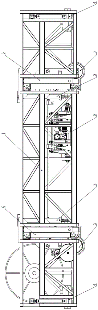
图1a是一实施方式中本发明钢轨焊缝全断面打磨作业车的结构正视图。Fig. 1a is a front view of the structure of a full-section grinding operation vehicle for rail weld seams in an embodiment.
图1b是一实施方式中本发明钢轨焊缝全断面打磨作业车的结构侧视图。Fig. 1b is a side view of the structure of the full-section grinding operation vehicle for rail weld seams in an embodiment.
图1c是一实施方式中本发明钢轨焊缝全断面打磨作业车的结构俯视图。Fig. 1c is a top view of the structure of the full-section grinding operation vehicle for rail weld seams in an embodiment.
图2a是一实施方式中本发明车架体的结构正视图。Fig. 2a is a front view of the structure of the frame body of the present invention in an embodiment.
图2b是一实施方式中本发明车架体的结构侧视图。Fig. 2b is a structural side view of the frame body of the present invention in an embodiment.
图2c 是一实施方式中本发明车架体的结构俯视图。Fig. 2c is a structural top view of the frame body of the present invention in an embodiment.
图3a 是一实施方式中本发明打磨装置的结构正视图。Fig. 3 a is a structural front view of the grinding device of the present invention in one embodiment.
图3b是一实施方式中本发明打磨装置的结构侧视图。Fig. 3b is a side view of the structure of the grinding device of the present invention in an embodiment.
图3c是一实施方式中本发明打磨装置的结构俯视图。Fig. 3c is a structural top view of the grinding device of the present invention in an embodiment.
图4 是一实施方式中本发明钢轨提升装置的结构图。Fig. 4 is a structural diagram of the rail lifting device of the present invention in an embodiment.
图5a 是一实施方式中本发明钢轨定位装置的结构正视图。Fig. 5a is a structural front view of the rail positioning device of the present invention in one embodiment.
图5b是一实施方式中本发明钢轨定位装置的结构俯视图。Fig. 5b is a structural top view of the rail positioning device of the present invention in an embodiment.
图6a 是一实施方式中本发明主动轮组结构的正视图。Fig. 6a is a front view of the structure of the driving wheel set of the present invention in an embodiment.
图6b是一实施方式中本发明主动轮组结构的侧视图。Fig. 6b is a side view of the driving wheel set structure of the present invention in an embodiment.
图6c 是一实施方式中本发明从动轮组结构的侧视图。Fig. 6c is a side view of the structure of the driven wheel set of the present invention in an embodiment.
图7a是一实施方式中本发明支腿系统的结构正视图。Fig. 7a is a front view of the structure of the outrigger system of the present invention in an embodiment.
图7b是一实施方式中本发明支腿系统的结构俯视图。Fig. 7b is a structural top view of the outrigger system of the present invention in an embodiment.
图7c是一实施方式中本发明支腿系统的结构侧视图。Fig. 7c is a side view of the structure of the outrigger system of the present invention in one embodiment.
图8a 是一实施方式中本发明钢轨焊缝全断面打磨作业车工作示意图(正视)。Fig. 8a is a working schematic diagram (front view) of the rail weld full-section grinding operation vehicle in one embodiment.
图8b 是一实施方式中本发明钢轨焊缝全断面打磨作业车工作示意图(侧视)。Fig. 8b is a working schematic diagram (side view) of the full-section grinding operation vehicle for rail weld seams in an embodiment.
图中:1.车架体 2.打磨装置 3.钢轨提升装置 4.钢轨定位装置 5.轮组系统 6.支腿系统 1-1.工字型钢 1-2.支撑液压缸 1-3.燕尾槽2-1.作业平台 2-2.轨头打磨装置2-3.轨腰打磨装置 2-4 .轨底打磨装置 2-5.平台驱动装置 3-1.承重梁 3-2.提升液压缸3-3.连接杆 3-4 .钢轨夹具 3-5. 限位套 4-1.定位箱 4-2.顶推液压缸 4-3.活动夹头4-4.固定夹头 4-5.摆动卡钳 5-1.轮组支腿 5-2.起降液压缸 5-3.车轮总成 5-4.驱动电机 5-5.传动齿轮组 6-1.支腿箱体 6-2 .L型横梁 6-3.支腿立柱 6-4. 横移液压缸 6-5.顶升液压缸。In the figure: 1. Frame body 2. Grinding device 3. Rail lifting device 4. Rail positioning device 5. Wheel set system 6. Outrigger system 1-1. I-shaped steel 1-2. Support hydraulic cylinder 1-3. Dovetail groove 2-1. Working platform 2-2. Rail head grinding device 2-3. Rail waist grinding device 2-4. Rail bottom grinding device 2-5. Platform driving device 3-1. Load beam 3-2. Lifting Hydraulic cylinder 3-3. Connecting rod 3-4. Rail clamp 3-5. Limit sleeve 4-1. Positioning box 4-2. Push hydraulic cylinder 4-3. Movable chuck 4-4. Fixed chuck 4 -5. Swing calipers 5-1. Wheel set outriggers 5-2. Lifting hydraulic cylinder 5-3. Wheel assembly 5-4. Drive motor 5-5. Transmission gear set 6-1. Outrigger box 6 -2. L-shaped beam 6-3. Outrigger column 6-4. Traversing hydraulic cylinder 6-5. Jacking hydraulic cylinder.
具体实施方式Detailed ways
下面结合附图对本发明作进一步说明,这种装置的结构和原理对本专业的人来说是非常清楚的。应当理解,此处所描述的具体实施例仅仅用以解释本发明,并不用于限定本发明。The present invention will be further described below in conjunction with accompanying drawing, and the structure and principle of this device are very clear to those skilled in the art. It should be understood that the specific embodiments described here are only used to explain the present invention, not to limit the present invention.
实施例1:钢轨焊缝全断面打磨作业车结构组成。Embodiment 1: Structural composition of a full-section grinding operation vehicle for rail welds.
参见图1a、图1b和图1c,本实施方式中,所述的打磨作业车由以下8个子系统组成:分别是车架体、打磨装置、钢轨提升装置、钢轨定位装置、轮组系统、支腿系统、自动控制系统、辅助系统。Referring to Fig. 1a, Fig. 1b and Fig. 1c, in this embodiment, the described grinding operation vehicle is composed of the following 8 subsystems: respectively, the frame body, the grinding device, the rail lifting device, the rail positioning device, the wheel system, the support Leg system, automatic control system, auxiliary system.
参见图2a、图2b和图2c,车架体是其他所有系统的载体,采用工字型钢与方形钢管焊接而成的立体矩形框架结构,工字型钢作为车架体主梁,方管辅助主梁受力、增加车架体刚度,形成车架体框架。车架体的四角设有支撑液压缸,在作业时支撑在地面或侧壁上。车架体沿纵向划分为五个区段,最中间的一段为作业区段,是打磨系统作业的空间。作业区段的两侧是支撑区段,是支腿系统、钢轨提升装置、钢轨定位装置的安装空间。车架体最外侧的两个区段是辅助区段、主要用于安装轮组系统、支撑液压缸、钢轨定位装置、以及辅助系统,其中一侧区段的上半部分空置,作为安装驾驶操作空间使用。Referring to Figure 2a, Figure 2b and Figure 2c, the frame body is the carrier of all other systems. It adopts a three-dimensional rectangular frame structure welded by I-shaped steel and square steel pipes. The beam is stressed to increase the rigidity of the frame body to form a frame body frame. The four corners of the frame body are provided with supporting hydraulic cylinders, which are supported on the ground or side walls during operation. The frame body is divided into five sections along the longitudinal direction, and the middle section is the working section, which is the space for the grinding system to work. Both sides of the working section are supporting sections, which are the installation space for the outrigger system, rail lifting device, and rail positioning device. The two outermost sections of the frame body are auxiliary sections, which are mainly used to install the wheel system, support hydraulic cylinders, rail positioning devices, and auxiliary systems. The upper half of one side section is vacant for installation and driving operations. space usage.
参见图3a、图3b和图3c,打磨装置是本发明功能实现的主要执行机构,打磨装置位于车架体最中间的作业区段,左右股钢轨对应位置各安装一套。打磨装置主要由作业平台、轨头打磨装置、轨腰打磨装置、轨底打磨装置、平台驱动装置组成。作业平台底部设有燕尾槽导轨,通过车架体上的燕尾槽与车架体活动连接。轨头打磨装置和轨腰打磨装置为两套,前后、左右交错对称布置,轨底打磨装置单独悬挂在作业平台外侧。以上五套打磨装置均采用两套燕尾槽滑动平台与作业平台连接,这两套滑动平台一套水平布置,一套竖向布置,实现打磨装置水平和竖向滑动。作业平台通过电机及丝杠来回驱动。Referring to Fig. 3a, Fig. 3b and Fig. 3c, the grinding device is the main actuator for realizing the functions of the present invention. The grinding device is located in the middle working section of the frame body, and one set is installed at the corresponding positions of the left and right steel rails. The grinding device is mainly composed of a working platform, a rail head grinding device, a rail waist grinding device, a rail bottom grinding device, and a platform driving device. There is a dovetail groove guide rail at the bottom of the working platform, which is movably connected with the frame body through the dovetail groove on the frame body. There are two sets of rail head grinding device and rail waist grinding device, which are symmetrically arranged in a staggered front and rear, left and right, and the rail bottom grinding device is hung separately on the outside of the working platform. The above five sets of grinding devices are connected to the work platform by two sets of dovetail sliding platforms. One of the two sets of sliding platforms is arranged horizontally and the other is vertically arranged to realize the horizontal and vertical sliding of the grinding device. The working platform is driven back and forth by a motor and a lead screw.
参见图4,钢轨提升装置用于提升钢轨,该装置一共设有四套,每股钢轨对应位置设有两套,均安装在车架体的支撑区段与作业区段的交界处,主要由承重梁、提升液压缸、连接杆、钢轨夹具、限位套组成。承重梁位于钢轨提升装置最上端,与车架体在该位置的横梁焊接,承重梁下方依次连接的是提升液压缸、连接杆、以及钢轨夹具,限位套设置在连接杆的中部,连杆从其中穿过,起到约束连接杆在水平方向摆动的功能。Referring to Figure 4, the rail lifting device is used to lift the rail. There are four sets of the device in total, and two sets are installed at the corresponding position of each rail. It is composed of load-bearing beam, lifting hydraulic cylinder, connecting rod, rail clamp and limit sleeve. The load-bearing beam is located at the uppermost end of the rail lifting device, and is welded to the crossbeam of the frame body at this position. The lifting hydraulic cylinder, connecting rod, and rail clamp are sequentially connected under the load-bearing beam. The limit sleeve is set in the middle of the connecting rod, and the connecting rod Passing through it plays a role of constraining the connecting rod from swinging in the horizontal direction.
参见图5a和图5b,钢轨定位装置用于对钢轨进行定位,为打磨系统作业创造一个基准,一共设有八套,每侧钢轨位置设置四套,其中两套设置在车架体纵向端部,两套设置在车架体的支撑区段,均与对应位置车架体钢梁焊接固定。钢轨定位装置主要由定位箱、顶推液压缸、活动夹头、固定夹头、摆动卡钳组成。定位箱由多块钢板焊接形成的箱型结构,在其下部钢轨对应位置设有开口,为钢轨升降预留空间。顶推液压缸固定在定位箱的内侧端,拉杆与活动夹头连接。活动夹头顶部设有燕尾槽导轨,可在定位箱上部燕尾槽中滑动,活动夹头的夹点为倒三角式,夹头的下表面与钢轨轨底上表面吻合,以防止钢轨左右摆动。固定夹头设置在定位箱的外侧端,其夹点与活动夹头的夹点位置对应,但均为可调式夹点,下表面也与钢轨轨底上表面吻合。摆动卡钳设置在定位箱下部开口处,一端通过销轴与其连接,另一端设有豁口,可扣住定位箱另一侧的壁板,摆动卡钳通过连杆连接活动夹头,可与活动夹头随动。Referring to Figure 5a and Figure 5b, the rail positioning device is used to position the rail and create a reference for the grinding system operation. There are eight sets in total, four sets are set on each side of the rail, and two sets are set at the longitudinal end of the frame body , the two sets are arranged on the supporting section of the frame body, and are welded and fixed to the steel beams of the frame body at the corresponding positions. The rail positioning device is mainly composed of a positioning box, a push hydraulic cylinder, a movable chuck, a fixed chuck, and a swing caliper. The positioning box is a box-shaped structure formed by welding multiple steel plates, and openings are provided at the corresponding positions of the lower rails to reserve space for the lifting of the rails. The jacking hydraulic cylinder is fixed on the inner side of the positioning box, and the pull rod is connected with the movable chuck. There is a dovetail groove guide rail on the top of the movable chuck, which can slide in the dovetail groove on the upper part of the positioning box. The clamp point of the movable chuck is an inverted triangle, and the lower surface of the chuck coincides with the upper surface of the bottom of the rail to prevent the rail from swinging left and right. The fixed chuck is arranged on the outer end of the positioning box, and its grip points correspond to the grip points of the movable chuck, but they are all adjustable grip points, and the lower surface also coincides with the upper surface of the rail bottom. The swing caliper is set at the opening of the lower part of the positioning box, one end is connected with it by a pin shaft, and the other end is provided with a gap, which can buckle the wall plate on the other side of the positioning box. Follow up.
参见图6a、图6b和图6c,轮组系统是打磨车的驱动走行部分,共设有四组,其中两组为主动轮组,另两组为从动轮组,轮组系统设置在车架体辅助区段靠近支撑区段的一侧,主要由轮组支腿,起降液压缸、车轮总成、驱动电机、传动齿轮组成。轮组支腿是两根方形钢管,方管上共设有四组圆孔,通过穿入销轴,分别与起降液压缸、车架体、离合拨叉连杆车轮总成活动连接,使轮组系统可绕连接车架体的轴旋转,实现起落动作。驱动电机安装在轮组支腿中部。传动齿轮安装在轮组支腿上,位于车轮总成与驱动电机之间,其由由一大一小两个齿轮组成,其外侧大齿轮上设有拨叉,可实现齿轮之间的离合。从动轮组与主动轮组的结构以及布置相同,两者的区别仅仅只是从动轮组无驱动电机和传动齿轮。Referring to Fig. 6a, Fig. 6b and Fig. 6c, the wheel set system is the driving part of the grinding car. There are four sets in total, two of which are driving wheel sets and the other two are driven wheel sets. The wheel set system is set on the frame The side of the body auxiliary section close to the support section is mainly composed of wheel set outriggers, lifting hydraulic cylinders, wheel assemblies, drive motors, and transmission gears. The outriggers of the wheel set are two square steel pipes. There are four groups of round holes on the square pipes. Through the pin shafts, they are respectively connected with the lifting hydraulic cylinder, the frame body, the clutch shift fork, the connecting rod and the wheel assembly. The wheel system can rotate around the axis connected to the frame body to realize the lifting and lowering action. The drive motor is installed in the middle part of the wheel set outrigger. The transmission gear is installed on the wheel set leg, between the wheel assembly and the drive motor, and it is composed of two gears, one large and one small, and a shift fork is arranged on the outer large gear to realize the clutch between the gears. The structure and arrangement of the driven wheel set and the driving wheel set are identical, and the difference between the two is only that the driven wheel set has no drive motor and transmission gear.
参见图7a、图7b和图7c,支腿系统是打磨车的最主要的支撑体系,安装在车架体支撑区段上部,主要由支腿箱体、L型横梁、支腿立柱、横移液压缸、顶升液压缸组成。支腿箱体是一个带有两个空腔的矩形箱体结构。L型横梁插入支腿箱体的空腔中,通过滑移导轨与支腿箱体接触并可相对滑动, L型横梁也为空腔结构,支腿立柱插入其下端的空腔中,通过滑移导轨与其接触并可相对滑动。横移液压缸布置在支腿箱体腔中,两端分别与支腿箱体及L型横梁连接,可实现 L型横梁向两侧伸缩。顶升液压缸布置在 L型横梁下部外侧,两端分别与 L型横梁及支腿立柱连接,实现支腿立柱上下伸缩。Referring to Fig. 7a, Fig. 7b and Fig. 7c, the outrigger system is the most important support system of the grinding vehicle, installed on the upper part of the support section of the frame body, mainly composed of outrigger box, L-shaped beam, outrigger column, lateral movement Composed of hydraulic cylinder and jacking hydraulic cylinder. The outrigger box is a rectangular box structure with two cavities. The L-shaped beam is inserted into the cavity of the outrigger box, and is in contact with the outrigger box through the sliding guide rail and can slide relatively. The L-shaped beam is also a cavity structure, and the outrigger column is inserted into the cavity at the lower end. The moving guide rail is in contact with it and can slide relatively. The transverse hydraulic cylinder is arranged in the outrigger box cavity, and the two ends are respectively connected with the outrigger box and the L-shaped beam, which can realize the expansion and contraction of the L-shaped beam to both sides. The jacking hydraulic cylinder is arranged on the outer side of the lower part of the L-shaped beam, and the two ends are respectively connected with the L-shaped beam and the outrigger column to realize the vertical expansion and contraction of the outrigger column.
自动控制系统主要包括监视系统、检测系统、磨头驱动控制系统、液压控制系统、伺服控制系统、走行变频控制系统。布置在车架体的辅助区段或其他相应的功能区段。主要用于对作业全过程进行监视,对焊缝打磨效果进行检查,以用于打磨系统、轮组系统、支腿系统的控制。The automatic control system mainly includes a monitoring system, a detection system, a grinding head drive control system, a hydraulic control system, a servo control system, and a walking frequency conversion control system. Arranged in the auxiliary section of the frame body or other corresponding functional sections. It is mainly used to monitor the whole process of operation and check the welding seam grinding effect, so as to control the grinding system, wheel system and outrigger system.
辅助系统主要包括卷线盘、液压泵站、液压管路、打磨操作平台、驾驶操作平台、储物格等组成。布置在车架体的辅助区段。主要用于操作打磨作业车,操作打磨系统,为整车提供电力、液压动力来源等。The auxiliary system mainly includes a reel, a hydraulic pump station, a hydraulic pipeline, a grinding operation platform, a driving operation platform, and a storage compartment. Arranged in the auxiliary section of the frame body. It is mainly used to operate the grinding operation vehicle, operate the grinding system, and provide electric power and hydraulic power source for the whole vehicle.
实施例2:钢轨焊缝全断面打磨作业车使用方法。Embodiment 2: The method of using the full-section grinding operation vehicle for rail welds.
参见图8a和图8b,将所述的打磨作业车吊装至正线轨道上,将轮组系统的传动齿轮组调节至分离状态后,采用轨道车将打磨作业车拖行至作业面,然后传动齿轮组调节至啮合状态,以操作打磨车行驶至需要打磨的钢轨接头位置,使钢轨接头位于打磨作业区域中间位置后,停车制动。Referring to Fig. 8a and Fig. 8b, hoist the grinding operation vehicle on the main line track, adjust the transmission gear set of the wheel system to the separated state, use the rail car to drag the grinding operation vehicle to the working surface, and then drive The gear set is adjusted to the meshing state to operate the grinding vehicle to drive to the position of the rail joint that needs to be polished, and after the rail joint is located in the middle of the grinding operation area, it stops and brakes.
操作钢轨定位装置的顶推液压缸打开活动夹头以及摆动卡钳,确保钢轨可以嵌入钢轨定位装置中。Operate the jacking hydraulic cylinder of the rail positioning device to open the movable chuck and swing the caliper to ensure that the rail can be embedded in the rail positioning device.
操作支腿系统的横移液压缸,将 L型横梁向外伸出到合适位置,操作支腿系统的顶升液压缸,将支腿立柱降下并支撑在基础面上,操作轮组装置的起降液压缸,将轮组系统升起收缩至车架体中,再操作顶升液压缸降低车架体高度,直至车架体底部坐落在基础面上,向下翻转车架体的支撑液压缸并向外伸出,使支撑液压缸斜撑在基础面或侧墙壁面上,保持车架体稳定牢固。Operate the lateral movement hydraulic cylinder of the outrigger system to extend the L-shaped beam to a suitable position, operate the jacking hydraulic cylinder of the outrigger system to lower the outrigger column and support it on the foundation surface, and operate the lifting of the wheel set device. Lower the hydraulic cylinder to raise and shrink the wheel system into the frame body, and then operate the jacking hydraulic cylinder to lower the height of the frame body until the bottom of the frame body sits on the foundation surface, and turn down the supporting hydraulic cylinder of the frame body And protrude outwards, so that the supporting hydraulic cylinder is diagonally braced on the foundation surface or the side wall surface, so as to keep the frame body stable and firm.
操作钢轨提升装置的提升液压缸,降下钢轨夹具,打开钢轨夹具并夹住钢轨,再操作提升液压缸提起钢轨,使钢轨嵌入钢轨定位装置中,操作钢轨定位装置的顶推液压缸推动活动夹头夹紧钢轨,此时摆动卡钳扣住定位箱一端的壁板。Operate the lifting hydraulic cylinder of the rail lifting device, lower the rail clamp, open the rail clamp and clamp the rail, and then operate the lifting hydraulic cylinder to lift the rail so that the rail is embedded in the rail positioning device, and operate the pushing hydraulic cylinder of the rail positioning device to push the movable chuck Clamp the rail, and at this moment, the swing caliper buckles the wall plate at one end of the positioning box.
操作检测系统对钢轨需要打磨的区域进行线性扫描检测,根据扫描检测结果确定每个打磨作业来回的磨头进给量,启动打磨作业程序,打磨完成后,操作检测系统再次对钢轨进行扫描检测,确认打磨效果。The operation detection system conducts linear scanning detection on the area of the rail that needs to be polished, determines the feed rate of the grinding head back and forth for each grinding operation according to the scanning detection results, and starts the grinding operation program. After the grinding is completed, the operation detection system scans the rail again. Confirm the sanding effect.
打磨完成后,操作钢轨定位装置的顶推液压缸打开活动夹头以及摆动卡钳,解除对钢轨的夹紧状态,操作提升液压缸降下钢轨夹具及钢轨,打开钢轨夹具,使其与钢轨分离,再操作提升液压缸升起钢轨夹具。After the grinding is completed, operate the jacking hydraulic cylinder of the rail positioning device to open the movable chuck and the swing caliper to release the clamping state of the rail, operate the lifting hydraulic cylinder to lower the rail clamp and the rail, open the rail clamp to separate it from the rail, and then Operate the lifting hydraulic cylinder to raise the rail clamp.
收起支撑液压缸并向上翻起固定,操作顶升液压缸升起车架体至合适高度,再操作起降液压缸将轮组系统降下并使车轮总成支撑在钢轨上,然后操作顶升液压缸将支腿立柱收起至最高位置,最后操作横移液压缸将 L型横梁向内收回,即完成一处钢轨焊缝打磨。Put away the support hydraulic cylinder and turn it up to fix it, operate the jacking hydraulic cylinder to raise the frame body to a suitable height, then operate the lifting hydraulic cylinder to lower the wheel system and support the wheel assembly on the rail, and then operate the jacking The hydraulic cylinder retracts the outrigger column to the highest position, and finally operates the traversing hydraulic cylinder to retract the L-shaped beam inward, which completes a rail weld seam grinding.
打磨作业全部完成后,将传动齿轮组调节至分离状态,通过轨道车将打磨作业车拖行至基地,再采用起重机将打磨作业吊装离开钢轨,放置在地面,即完成打磨作业的退场。After all the grinding work is completed, the transmission gear set is adjusted to the separated state, the grinding operation vehicle is dragged to the base by a rail car, and then the grinding work is hoisted away from the rail by a crane and placed on the ground, that is, the exit of the grinding work is completed.
Claims (8)
Priority Applications (1)
| Application Number | Priority Date | Filing Date | Title |
|---|---|---|---|
| CN201810902082.7A CN108842542B (en) | 2018-08-09 | 2018-08-09 | Full-section grinding operation vehicle for rail weld seam and using method thereof |
Applications Claiming Priority (1)
| Application Number | Priority Date | Filing Date | Title |
|---|---|---|---|
| CN201810902082.7A CN108842542B (en) | 2018-08-09 | 2018-08-09 | Full-section grinding operation vehicle for rail weld seam and using method thereof |
Publications (2)
| Publication Number | Publication Date |
|---|---|
| CN108842542A CN108842542A (en) | 2018-11-20 |
| CN108842542B true CN108842542B (en) | 2023-05-12 |
Family
ID=64195631
Family Applications (1)
| Application Number | Title | Priority Date | Filing Date |
|---|---|---|---|
| CN201810902082.7A Active CN108842542B (en) | 2018-08-09 | 2018-08-09 | Full-section grinding operation vehicle for rail weld seam and using method thereof |
Country Status (1)
| Country | Link |
|---|---|
| CN (1) | CN108842542B (en) |
Families Citing this family (2)
| Publication number | Priority date | Publication date | Assignee | Title |
|---|---|---|---|---|
| CN112872708A (en) * | 2021-01-24 | 2021-06-01 | 南京波亚登汽车用品有限公司 | Train rail overhauls and changes device |
| CN112832076A (en) * | 2021-03-18 | 2021-05-25 | 中铁上海工程局集团有限公司 | Derusting device and derusting method for steel rails |
Citations (5)
| Publication number | Priority date | Publication date | Assignee | Title |
|---|---|---|---|---|
| EP1400629A2 (en) * | 2002-09-20 | 2004-03-24 | Wilfried Scherf | Grinding machine for rails, especially for rails of container cranes |
| CN203096537U (en) * | 2013-01-11 | 2013-07-31 | 成都市新筑路桥机械股份有限公司 | Steel rail high speed polishing train |
| CN103821052A (en) * | 2014-03-12 | 2014-05-28 | 唐山昆铁科技有限公司 | Middle-sized grinding wagon |
| WO2017147488A2 (en) * | 2016-02-24 | 2017-08-31 | Holland, L.P. | Portable rail weld milling machine apparatus and methods of using the same |
| CN107964840A (en) * | 2017-11-24 | 2018-04-27 | 中铁上海工程局集团有限公司 | A kind of telescopic way traffic laterally withdraws multifunction operation vehicle elevation and application method |
-
2018
- 2018-08-09 CN CN201810902082.7A patent/CN108842542B/en active Active
Patent Citations (5)
| Publication number | Priority date | Publication date | Assignee | Title |
|---|---|---|---|---|
| EP1400629A2 (en) * | 2002-09-20 | 2004-03-24 | Wilfried Scherf | Grinding machine for rails, especially for rails of container cranes |
| CN203096537U (en) * | 2013-01-11 | 2013-07-31 | 成都市新筑路桥机械股份有限公司 | Steel rail high speed polishing train |
| CN103821052A (en) * | 2014-03-12 | 2014-05-28 | 唐山昆铁科技有限公司 | Middle-sized grinding wagon |
| WO2017147488A2 (en) * | 2016-02-24 | 2017-08-31 | Holland, L.P. | Portable rail weld milling machine apparatus and methods of using the same |
| CN107964840A (en) * | 2017-11-24 | 2018-04-27 | 中铁上海工程局集团有限公司 | A kind of telescopic way traffic laterally withdraws multifunction operation vehicle elevation and application method |
Also Published As
| Publication number | Publication date |
|---|---|
| CN108842542A (en) | 2018-11-20 |
Similar Documents
| Publication | Publication Date | Title |
|---|---|---|
| CN110000458B (en) | Steel reinforcement cage seam welder | |
| CN107964840B (en) | Telescopic bidirectional operation transverse evacuation multifunctional operation vehicle and use method | |
| CN113979319A (en) | Municipal administration heating pipe network lays installing the system | |
| CN102615383A (en) | Box girder production line of front suspension arm frame | |
| WO2014094339A1 (en) | Gantry-type hull section marking machine | |
| CN105312798A (en) | Steel structure numerical control assembly center | |
| CN207749373U (en) | A kind of telescopic way traffic laterally withdraws multifunction operation vehicle elevation | |
| WO2019228304A1 (en) | Manufacturing tool for welding u-shaped rib of orthotropic plate unit, and assembly line and method | |
| CN211540030U (en) | Workpiece moving, jacking, clamping and deflection welding mechanism | |
| CN106988689B (en) | An automatic drilling tool moving device of a drilling rig for land scientific drilling | |
| CN103341679A (en) | Large-diameter long-pipe-fitting pipe-end cutting device | |
| CN114808567A (en) | Railway line component replacement gantry crane device and operation method thereof | |
| CN108842542A (en) | Steel rail welding line tunneling boring polishing operation vehicle and its application method | |
| CN109989308B (en) | Seamless rail welding repair vehicle with independent running workshops and repair method | |
| CN113414539A (en) | Elbow joint welding clamping device and method for water conservancy construction | |
| CN208884286U (en) | Steel rail welding line tunneling boring polishing operation vehicle | |
| CN208051447U (en) | A kind of locking device for pipe fitting clamping | |
| CN108756743B (en) | Soil normal position direct pushing type sampling and restoring integrated drilling machine | |
| CN203356810U (en) | Pipe end cutting device of long large-diameter pipe fittings | |
| CN206509679U (en) | The mounting and positioning device of cast pipe union | |
| CN115355359A (en) | Municipal pipeline construction device based on lifting hook seat and use method | |
| CN115008071A (en) | An automatic welding device for engineering vehicle box beams | |
| CN201457412U (en) | Device capable of quickly retracting and extending measuring wheels or guide wheel of rail examination instrument | |
| CN211255031U (en) | Hoisting apparatus is used in bridge engineering construction | |
| CN109898375B (en) | Hydraulic rail replacing machine |
Legal Events
| Date | Code | Title | Description |
|---|---|---|---|
| PB01 | Publication | ||
| PB01 | Publication | ||
| SE01 | Entry into force of request for substantive examination | ||
| SE01 | Entry into force of request for substantive examination | ||
| GR01 | Patent grant | ||
| GR01 | Patent grant | ||
| TR01 | Transfer of patent right |
Effective date of registration: 20230607 Address after: 200436 No. 278, three JIANGCHANG Road, Jingan District, Shanghai Patentee after: SHANGHAI CIVIL ENGINEERING Co.,Ltd. OF CREC Patentee after: HUAHAI ENGINEERING Co.,Ltd. OF CREC SHANGHAI Patentee after: China Railway Shanghai Engineering Bureau Group (Suzhou) Rail Transit Technology Research Institute Co.,Ltd. Address before: 200436 No. 278, three JIANGCHANG Road, Jingan District, Shanghai Patentee before: SHANGHAI CIVIL ENGINEERING Co.,Ltd. OF CREC Patentee before: HUAHAI ENGINEERING Co.,Ltd. OF CREC SHANGHAI |
|
| TR01 | Transfer of patent right |