CN108666845B - Coil feeding method of automatic antenna terminal laminating machine - Google Patents
Coil feeding method of automatic antenna terminal laminating machine Download PDFInfo
- Publication number
- CN108666845B CN108666845B CN201810449779.3A CN201810449779A CN108666845B CN 108666845 B CN108666845 B CN 108666845B CN 201810449779 A CN201810449779 A CN 201810449779A CN 108666845 B CN108666845 B CN 108666845B
- Authority
- CN
- China
- Prior art keywords
- plate
- cutting
- fixed
- stamping
- coil
- Prior art date
- Legal status (The legal status is an assumption and is not a legal conclusion. Google has not performed a legal analysis and makes no representation as to the accuracy of the status listed.)
- Expired - Fee Related
Links
Images


Classifications
-
- H—ELECTRICITY
- H01—ELECTRIC ELEMENTS
- H01R—ELECTRICALLY-CONDUCTIVE CONNECTIONS; STRUCTURAL ASSOCIATIONS OF A PLURALITY OF MUTUALLY-INSULATED ELECTRICAL CONNECTING ELEMENTS; COUPLING DEVICES; CURRENT COLLECTORS
- H01R43/00—Apparatus or processes specially adapted for manufacturing, assembling, maintaining, or repairing of line connectors or current collectors or for joining electric conductors
- H01R43/04—Apparatus or processes specially adapted for manufacturing, assembling, maintaining, or repairing of line connectors or current collectors or for joining electric conductors for forming connections by deformation, e.g. crimping tool
- H01R43/048—Crimping apparatus or processes
-
- B—PERFORMING OPERATIONS; TRANSPORTING
- B21—MECHANICAL METAL-WORKING WITHOUT ESSENTIALLY REMOVING MATERIAL; PUNCHING METAL
- B21F—WORKING OR PROCESSING OF METAL WIRE
- B21F1/00—Bending wire other than coiling; Straightening wire
-
- B—PERFORMING OPERATIONS; TRANSPORTING
- B21—MECHANICAL METAL-WORKING WITHOUT ESSENTIALLY REMOVING MATERIAL; PUNCHING METAL
- B21F—WORKING OR PROCESSING OF METAL WIRE
- B21F1/00—Bending wire other than coiling; Straightening wire
- B21F1/02—Straightening
- B21F1/026—Straightening and cutting
-
- B—PERFORMING OPERATIONS; TRANSPORTING
- B21—MECHANICAL METAL-WORKING WITHOUT ESSENTIALLY REMOVING MATERIAL; PUNCHING METAL
- B21F—WORKING OR PROCESSING OF METAL WIRE
- B21F23/00—Feeding wire in wire-working machines or apparatus
-
- H—ELECTRICITY
- H01—ELECTRIC ELEMENTS
- H01R—ELECTRICALLY-CONDUCTIVE CONNECTIONS; STRUCTURAL ASSOCIATIONS OF A PLURALITY OF MUTUALLY-INSULATED ELECTRICAL CONNECTING ELEMENTS; COUPLING DEVICES; CURRENT COLLECTORS
- H01R2201/00—Connectors or connections adapted for particular applications
- H01R2201/02—Connectors or connections adapted for particular applications for antennas
Abstract
The invention relates to a material rolling and feeding method of an automatic antenna terminal laminating machine, which comprises the following steps: the waste material cutting and collecting device moves downwards, the coil stock in the material tray is pressed, the shift cylinder drives the coil stock to move, the coil stock straightening device keeps the coil stock flat all the time, the coil stock stamping device moves, thereby the lifting component and the pressing component move right above the roller guide rail with the rising radian, when the coil stock moves to the position right below the cutting elbow component, the cutting elbow component moves downwards to enable the cutting elbow and the cutting elbow fixing plate to be matched and punched downwards, the copper sheet on the coil stock is cut and punched into the pressing component, then the stamping push-pull cylinder retracts to return the lifting assembly and the pressing assembly to the original positions, the pushing cylinder drives the linear connecting rod to swing, the waste material is cut off by the cutting blade and enters the waste material collecting box through the waste material outlet groove.
Description
The present application is a divisional application of a patent with the application number of 2016104858947, 2016, 06, 29, entitled "coil feeding mechanism of an antenna terminal automatic laminating machine".
Technical Field
The invention relates to the field of mechanical automation, in particular to a coil feeding mechanism of an automatic antenna terminal laminating machine.
Background
At present, antennas in computers, mobile phones and tablet computers are formed by combining wire ends and terminals, the coil material feeding mechanism of the existing automatic antenna terminal laminating machine is complex in structure, low in efficiency, low in precision and unstable in operation, assembly problems are easy to occur when large-batch assembly line production is manually completed by workers, the production process has high requirements on the assembly technology of the workers, once the workers flow and change, the production efficiency and the product quality are affected, the service life and the service performance of products are directly affected, and therefore improvement on the coil material feeding mechanism of the existing automatic antenna terminal laminating machine is necessary.
Disclosure of Invention
The invention mainly solves the technical problem of providing the coil feeding mechanism of the automatic laminating machine for the antenna terminal, which has the advantages of stable operation, good cutting and bending effects, convenient lamination, effective treatment of waste materials, small workpiece abrasion, long service life, improvement of production efficiency and reduction of production cost.
In order to solve the technical problems, the invention adopts a technical scheme that: the coil feeding mechanism of the automatic antenna terminal laminating machine comprises a coil feeding device, a coil straightening device, a coil cutting and bending device, a coil stamping device and a waste cutting and collecting device, wherein the coil feeding device and the coil straightening device are sequentially arranged on a rack, the coil cutting and bending device is positioned on the rack above the coil straightening device, the coil stamping device is positioned on the rack below the coil straightening device, the coil feeding device comprises a coil, a stepped shaft, a locking ring and a flange seat, the coil passes through the stepped shaft and is fixed with the stepped shaft through the locking ring, two ends of the stepped shaft are fixed on the rack through the flange seat, and the coil straightening device comprises a guide plate, a pressing sheet, a front straightening mounting plate, a rear straightening mounting plate, a polyurethane roller supporting column, An elliptical gasket, a support column, a first buffer spring and a circular gasket, wherein a front straightening mounting plate and a rear straightening mounting plate are arranged on the upper end surface of the frame, the upper planes of the front straightening mounting plate and the rear straightening mounting plate are both provided with guide plates which are provided with guide grooves and correspond to the discharge ports, both ends of the upper plane of the guide plate provided with the guide grooves are provided with pressing sheets which are fixed by screws, two pillars are fixed on the front straightening mounting plate through screws, the two pillars are respectively positioned at two sides of the guide plate provided with the guide groove, a polyurethane roller supporting column is sleeved on the pillar, a polyurethane roller is sleeved on the polyurethane roller supporting column, the top ends of the pillars positioned at the same side of the guide plate provided with the guide groove are connected through an oval gasket, a circular gasket is arranged on the strut sleeved with the polyurethane roller supporting column, and a first buffer spring is sleeved on the strut between the elliptical gasket and the circular gasket;
preferably, the coil stock cutting and bending device comprises a transplanting assembly, a bending assembly and a cut-off elbow assembly, the transplanting assembly comprises a transverse linear slide rail, a coil stock cutting and bending mounting plate, a first buffer device, a left push-pull cylinder, a right push-pull cylinder, a push plate, a longitudinal linear slide rail, a push plate, a transplanting device connecting plate, a cut-off and bending support plate, a cantilever pin and a limiting roller, the coil stock cutting and bending mounting plate is fixed on a rack above a front straightening mounting plate, a first buffer device is fixed at the front end of the coil stock cutting and bending mounting plate through screws, two transverse linear slide rails parallel in the horizontal direction are fixed on the lateral surface of the coil stock cutting and bending mounting plate through screws, an arc-shaped chute is arranged on the coil stock cutting and bending mounting plate between the transverse linear slide rails, the push plate is fixed on a slide block of the transverse linear slide rail, and the lateral surface of the, the left and right push-pull air cylinder is fixed on the push plate, the push plate is fixedly provided with a coil cutting and bending mounting plate through a reinforcing rib, two mutually parallel longitudinal linear slide rails are fixed on the push plate through screws, a rectangular groove is formed in the push plate between the longitudinal linear slide rails, a transplanting device connecting plate is fixed on a slide block of each longitudinal linear slide rail, a cantilever pin is fixed on the transplanting device connecting plate through a screw, the other end of the cantilever pin penetrates through the rectangular groove and is provided with a limiting roller, the limiting roller is locked in an arc-shaped chute on the coil cutting and bending mounting plate, a cutting and bending supporting plate is fixed on the side surface of the transplanting device connecting plate through the reinforcing rib, a bending assembly is fixed on the left side of the lower plane of the cutting and bending supporting plate through a fixing device, and the bending assembly comprises a first pull air cylinder, a first, The bending device comprises a bending connecting plate and a bending head mounting plate, wherein two first guide rods penetrate through mounting holes on the left side of the lower plane of the cutting and bending supporting plate, the first guide rods are fixed with the cutting and bending supporting plate through oil-free bushes, the lower ends of the two first guide rods are fixed with the upper end face of the bending connecting plate through fixing devices, a first pulling cylinder is fixed on the cutting and bending supporting plate between the two first guide rods through a flange, the piston head of the first pulling cylinder penetrates through the cutting and bending supporting plate and is connected with the upper end face of the bending connecting plate through a connecting device, an adjusting nut is fixed on the bending connecting plate, the lower end face of the bending connecting plate is connected with the upper end face of the bending head mounting plate through a buffering adjusting column, a spring is sleeved on the buffering adjusting column between the bending connecting plate and the bending head mounting plate, a bending head is fixed on the lower end face of the bending, the bend limiting clamp is fixed on the lower end face of the bend mounting plate through a screw, the cut-off bend assembly is fixed on the right side of the lower plane of the cut-off bend mounting plate through a fixing device, the cut-off bend assembly comprises a second lifting cylinder, second guide rods, a regulating column, a buffer regulating rod, a cut-off bend and a cut-off bend fixing plate, a cut-off bend connecting plate, a cut-off bend mounting plate and a T-shaped clamping groove, the two second guide rods penetrate through mounting holes on the right side of the lower plane of the cut-off bend mounting plate and are fixed with the cut-off bend mounting plate through oilless bushings, the lower ends of the two second guide rods are fixed with the upper end face of the cut-off bend connecting plate through the fixing device, the second lifting cylinder is fixed on the cut-off bend mounting plate between the two second guide rods through a flange, and the piston, the lower end face of the cutting elbow connecting plate is fixed with the upper end face of the cutting elbow mounting plate through a regulating column, the lower end face of the cutting elbow mounting plate is connected with a cutting elbow through a buffer regulating rod, a spring is sleeved on the buffer regulating rod between the cutting elbow mounting plate and the cutting elbow, the cutting elbow is locked on a cutting elbow fixing plate through an E-shaped hinge pin, and the cutting elbow fixing plate is fixed on the lower end face of the cutting elbow mounting plate through a screw;
preferably, the coil stamping device comprises a lifting assembly, a press-fit assembly, a stamping device mounting plate, a second buffer device, a stamping device linear slide rail and a stamping displacement cylinder, the stamping device mounting plate is fixed on the machine frame under the cutting elbow assembly, the stamping displacement cylinder is fixed at the right end of the upper plane of the stamping device mounting plate through a cylinder fixing device, the second buffer device is fixed at the left end and the right end of the upper plane of the stamping device mounting plate, the stamping device linear slide rails which are parallel to each other in the horizontal direction are fixed on the upper planes of the stamping device mounting plates at the two sides of the second buffer device through screws, the lifting assembly is fixed on a slide block of the stamping device linear slide rail, the press-fit assembly is arranged above the lifting assembly, and the lifting assembly comprises a stamping device push plate, a guide plate with an elliptical chute, a pushing linear slide rail, a roller guide, The stamping device comprises a stamping push-pull cylinder, a stamping device connecting plate, a stamping device supporting plate, a roller fixing seat, a stamping support column, a spring gasket and a return spring, wherein a pushing plate of the stamping device is fixed on a sliding block of a linear sliding rail of the stamping device through screws, the pushing plate of the stamping device corresponds to two second buffer devices on the plane of a mounting plate of the stamping device, the right side of the pushing plate of the stamping device is connected with a piston head of a stamping shift cylinder through a connecting device, a guide plate with an elliptical sliding groove is fixed above the pushing plate of the stamping device through the support column, a roller guide rail with a rising radian is fixed on the plane of the pushing plate of the stamping device through screws, one end of the roller guide rail with the rising radian penetrates through the elliptical sliding groove of the guide plate with the elliptical sliding groove, the stamping push-pull cylinder is fixed on the guide plate with the elliptical, a stamping device connecting plate with a square groove is fixed on a slide block for pushing a linear slide rail, one side of the stamping device connecting plate is connected with a piston head of a stamping push-pull air cylinder through a connecting device, a stamping device supporting plate is arranged on the upper plane of the stamping device connecting plate, a roller fixing seat is fixed on the lower plane of the stamping device supporting plate through screws and penetrates through the square groove of the stamping device connecting plate, a roller is fixed between the roller fixing seats, the roller penetrates through an oval sliding groove on a guide plate with an oval sliding groove and is embedded into a roller guide rail with a rising radian, four corners of the stamping device supporting plate are fixed on the upper plane of the stamping device connecting plate through stamping supporting columns, the bottom ends of the stamping supporting columns extend downwards into the oval sliding groove of the guide plate with the oval sliding groove, nuts are fixed at the bottoms of the stamping supporting columns, spring gaskets, the pressing assembly is fixed on the upper plane of the supporting plate of the stamping device and comprises a stamping head, a stamping head mounting plate, supporting columns, a stamping spring, a cylindrical pin and a stamping sheet, wherein four supporting columns penetrating through the stamping head mounting plate are sequentially arranged on the upper end face of the supporting plate of the stamping device;
preferably, the waste cutting and collecting device comprises a shifting manipulator assembly, a waste cutting assembly and a waste collecting assembly, the shifting manipulator assembly comprises a shifting manipulator supporting plate, the shifting manipulator supporting plate is fixed on the rear straightening mounting plate through a pillar, two sides of the upper plane of the shifting manipulator supporting plate are fixedly provided with a mandrel support through screws, a mandrel penetrates through a positioning block, two ends of the mandrel are fixed with the mandrel support, a pressing plate with a mounting hole is fixed on the upper plane of the positioning block, a lifting cylinder is fixed on the upper end surface of the pressing plate with the mounting hole through a cylinder fixing device, the piston head of the lifting cylinder penetrates through the mounting hole of the pressing plate, the piston head of the lifting cylinder is connected with a shifting connecting plate through a connecting device, a guide post is fixed on the shifting connecting plate, the upper part of the guide post is fixed in the mounting hole of, a second buffer spring is sleeved on a guide pillar between a bottom plate with a punch and a shifting connecting plate, a press plate with a mounting hole and the left and right sides of the bottom plate with the punch are fixed through guide plates, the two guide plates are fixed through a connecting block, one side of a shifting manipulator supporting plate is provided with a shifting push plate, a shifting cylinder is fixed on the shifting push plate through a cylinder fixing device, a piston head of the shifting cylinder penetrates through the shifting push plate, the piston head of the shifting cylinder is fixed on the guide plates through a T-shaped clamping groove plate, a waste cutting assembly comprises a fixing flange with a chute, the fixing flange with the chute is fixed at the front end of a rear straightening mounting plate through a reinforcing rib, a waste outlet mounting plate with the chute is fixed on the left side of the fixing flange with the chute through a circular pillar, and two linear guide shafts are fixed at a chute diagonal position between the fixing flange with the, the cover has the right angle pitman arm on the straight line guiding axle, two right angle pitman arm bottoms are articulated with linear connection pole, be fixed with cutting blade in right angle pitman arm upper portion butt joint department, be fixed with push cylinder through the fixing base in the frame, the push cylinder piston head passes through cylinder connecting device and coupling joint, the shaft coupling passes the rotation axis, the rotation axis articulates in the middle of linear connection pole, the garbage collection subassembly includes waste outlet groove, waste material centralized box and collecting box backup pad, there is waste outlet groove through the fix with screw in waste outlet mounting panel spout department, be fixed with waste material centralized box under waste outlet groove, waste material centralized box is put in the collecting box backup pad, the collecting box backup pad is fixed at the frame up end.
The invention has the beneficial effects that: the coil feeding mechanism of the automatic antenna terminal laminating machine has the advantages of stable operation, good cutting and bending effects, convenience in laminating, effective treatment of waste materials, small abrasion of workpieces, long service life, improvement of production efficiency and reduction of production cost.
Drawings
Fig. 1 is a schematic structural view of a coil feeding mechanism of an automatic antenna terminal laminating machine according to the present invention;
fig. 2 is a schematic structural view of a coil feeding device, a coil straightening device and a waste cutting and collecting device of a coil feeding mechanism of an automatic antenna terminal laminating machine according to the present invention;
fig. 3 is a partially enlarged schematic view of a coil straightening device of a coil feeding mechanism of the automatic antenna terminal laminating machine according to the present invention;
fig. 4 is a schematic structural view of a coil cutting and bending device of a coil feeding mechanism of an automatic antenna terminal laminating machine according to the present invention;
fig. 5 is a partial schematic view of a coil cutting and bending device of a coil feeding mechanism of the automatic antenna terminal laminating machine according to the present invention;
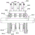
FIG. 6 is a schematic structural view of a coil stamping device of a coil feeding mechanism of the automatic antenna terminal laminating machine according to the present invention;
fig. 7 is a partial schematic view of a coil stamping device of a coil feeding mechanism of the automatic antenna terminal laminating machine according to the present invention;
fig. 8 is a schematic view of a first three-dimensional structure of a shifting manipulator assembly of the coil feeding mechanism of the automatic antenna terminal laminating machine according to the present invention;
fig. 9 is a second three-dimensional structural schematic diagram of the shift manipulator assembly of the coil feeding mechanism of the automatic antenna terminal laminating machine according to the present invention;
fig. 10 is a partial schematic view of a waste cutting assembly of the coil feeding mechanism of the automatic antenna terminal laminating machine of the present invention;
fig. 11 is a partial structural view of the waste cutting assembly and a structural view of the waste collecting assembly of the coil feeding mechanism of the automatic antenna terminal laminating machine according to the present invention.
Detailed Description
The preferred embodiments of the present invention will be described in detail below with reference to the accompanying drawings so that the advantages and features of the invention can be more readily understood by those skilled in the art, and the scope of the invention will be more clearly defined.
Referring to fig. 1 to 3, a coil feeding mechanism of an antenna terminal automatic laminating machine includes a coil feeding device 21, a coil straightening device 22, a coil cutting and bending device 23, a coil stamping device 24 and a scrap cutting and collecting device 25, the coil feeding device 21 and the coil straightening device 22 are sequentially arranged on a rack, the coil cutting and bending device 23 is located on the rack above the coil straightening device 22, the coil stamping device 24 is located on the rack below the coil straightening device 22, the coil feeding device 21 includes a coil 211, a stepped shaft 212, a locking ring 213 and a flange seat 214, the coil 211 passes through the stepped shaft 212 and is fixed to the stepped shaft 212 through the locking ring 213, two ends of the stepped shaft 212 are fixed to the rack through the flange seat 214, the coil straightening device 22 includes a guide plate 221, a guide groove, The pressing sheet 222, the front straightening mounting plate 223, the rear straightening mounting plate 224, the polyurethane roller 225, the polyurethane roller support column 226, the oval spacer 227, the strut 228, the first buffer spring 229 and the circular spacer 2210, the front straightening mounting plate 223 and the rear straightening mounting plate 224 are arranged on the upper end surface of the frame, the guide plates 221 with guide grooves corresponding to the discharge holes are arranged on the upper planes of the front straightening mounting plate 223 and the rear straightening mounting plate 224, the pressing sheet 222 fixed through screws is arranged at two ends of the upper plane of the guide plate 221 with the guide grooves, the two struts 228 are fixed on the front straightening mounting plate 223 through screws, the two struts 228 are respectively positioned at two sides of the guide plate 221 with the guide grooves, the polyurethane roller support column 226 is sleeved on the strut 228, the polyurethane roller 225 is sleeved on the polyurethane roller support column 226, the top ends of the struts 228 positioned at the same side of the guide plate 221 with the guide grooves are connected through the oval spacer, a circular gasket 2210 is arranged on the strut 228 sleeved with the polyurethane roller supporting column 226, and a first buffer spring 229 is sleeved on the strut 228 between the oval gasket 227 and the circular gasket 2210;
referring to fig. 4 and 5, the coil cutting and bending device 23 includes a transplanting assembly 231, a bending assembly 232 and a cutting elbow assembly 233, the transplanting assembly 231 includes a transverse linear slide rail 2311, a coil cutting and bending mounting plate 2312, a first buffer device 2313, a left and right push-pull cylinder 2314, a push plate 2315, a longitudinal linear slide rail 2316, a push plate 2317, a transplanting device connecting plate 2318, a cutting and bending support plate 2319, a cantilever pin 23110 and a limit roller 23111, the coil cutting and bending mounting plate 2312 is fixed on the rack above the front straightening mounting plate 223, the first buffer device 2313 is fixed at the front end of the coil cutting and bending mounting plate 2312 through screws, two transverse linear slide rails 2311 parallel in the horizontal direction are fixed at the side of the coil cutting and bending mounting plate 2312 through screws, an arc chute 23121 is arranged on the coil cutting and bending mounting plate 2312 between the transverse linear slide rails 2311, the push plate 2317 is fixed on the slide block of the transverse linear slide rail 2311, the side surface of a pushing plate 2317 is fixed with a piston rod of a left and right pushing and pulling cylinder 2314 through a U-shaped clamping groove 23171, the left and right pushing and pulling cylinder 2314 is fixed on a pushing plate 2315, the pushing plate 2315 is fixed with a coil cutting and bending mounting plate 2312 through a reinforcing rib, the pushing plate 2317 is fixed with two mutually parallel longitudinal linear sliding rails 2316 through screws, a rectangular groove 23172 is arranged on the pushing plate 2317 between the longitudinal linear sliding rails 2316, a transplanting device connecting plate 2318 is fixed on a sliding block of the longitudinal linear sliding rail 2316, a cantilever pin 23110 is fixed on the transplanting device connecting plate 2318 through a screw, the other end of the cantilever pin 23110 penetrates through the rectangular groove 23172 and is provided with a limiting roller 23111, the limiting roller 23111 is locked in an arc-shaped sliding groove 23121 on the coil cutting and bending mounting plate 2312, a cutting and bending support plate 2319 is fixed on the side surface of the transplanting device connecting plate 2318 through a reinforcing rib, a, the bending assembly 232 comprises a first pulling cylinder 2321, a first guide rod 2322, an adjusting nut 2323, a buffering adjusting column 2324, an adjusting rod 2325, a bending head 2326, a bending head limiting clamp 2327, a bending connecting plate 2328 and a bending head mounting plate 2329, wherein the two first guide rods 2322 penetrate through a mounting hole on the left side of the lower plane of the cutting and bending supporting plate 2319, the first guide rods 2322 are fixed with the cutting and bending supporting plate 2319 through oil-free bushings, the lower ends of the two first guide rods 2322 are fixed with the upper end face of the bending connecting plate 2328 through fixing devices, the first pulling cylinder 2321 is fixed on the cutting and bending supporting plate 2319 between the two first guide rods 2322 through a flange, the piston head of the first pulling cylinder 2321 penetrates through the cutting and bending supporting plate 2319 and is connected with the upper end face of the bending connecting device and the bending connecting plate 2328, the adjusting nut 2323 is fixed on the bending connecting plate 2328, the lower end face of the bending connecting plate 2328 is connected with, a spring is sleeved on a buffering adjusting column 2324 between a bending connecting plate 2328 and a bending head mounting plate 2329, a bending head 2326 is fixed on the lower end face of the bending head mounting plate 2329 through an adjusting rod 2325, a 'V' -shaped groove is arranged on the bending head 2326, the bending head 2326 is fixed in a bending head limit clamp 2327, the bending head limit clamp 2327 is fixed on the lower end face of the bending head mounting plate 2329 through a screw, a cutting elbow component 233 is fixed on the right side of the lower plane of the cutting bending support plate 2319 through a fixing device, the cutting elbow component 233 comprises a second lifting cylinder 2331, a second guide rod 2332, an adjusting column 2333, a buffering adjusting rod 2334, a cutting elbow 2335, a cutting elbow fixing plate 2336, a cutting elbow connecting plate 2337, a cutting elbow mounting plate 2338 and a 'T' -shaped clamping groove 2339, two second guide rods 2332 penetrate through mounting holes on the right side of the lower plane of the cutting bending support plate 2319, and the second guide rods 2332, the lower ends of two second guide rods 2332 are fixed with the upper end surface of a cutting elbow connecting plate 2337 through fixing devices, a second pull cylinder 2331 is fixed on the cutting bending supporting plate 2319 between the two second guide rods 2332 through a flange, the piston head of the second pull cylinder 2331 penetrates through the cutting bending supporting plate 2319 and is fixed on the upper end surface of the cutting elbow connecting plate 2337 through a T-shaped clamping groove 2339, the lower end surface of the cutting elbow connecting plate 2337 is fixed with the upper end surface of the cutting elbow mounting plate 2338 through an adjusting column 2333, the lower end surface of the cutting elbow mounting plate 2338 is connected with the cutting elbow 2335 through a buffer adjusting rod 2334, a spring is sleeved on the buffer adjusting rod 2334 between the cutting elbow mounting plate 2338 and the cutting elbow 2335, the cutting elbow 2335 is locked on the cutting elbow fixing plate 2336 through an E-shaped hinge pin, and the cutting elbow fixing plate 2336 is fixed on the lower;
referring to fig. 6 and 7, the coil stamping device includes a lifting assembly 241, a pressing assembly 242, a stamping device mounting plate 243, a second buffer device 244, a stamping device linear slide rail 245 and a stamping displacement cylinder 246, the stamping device mounting plate 243 is fixed on the frame right below the cut-off elbow assembly 233, the stamping displacement cylinder 246 is fixed on the right end of the upper plane of the stamping device mounting plate 243 through a cylinder fixing device, the second buffer device 244 is fixed on the left end and the right end of the upper plane of the stamping device mounting plate 243, the stamping device linear slide rails 245 parallel to each other in the horizontal direction are fixed on the upper planes of the stamping device mounting plates 243 on the two sides of the second buffer device 244 through screws, the lifting assembly 241 is fixed on the slide block of the stamping device linear slide rail 245, the pressing assembly 242 is arranged above the lifting assembly 241, and the lifting assembly 241 includes a stamping device push plate 2411 and a guide plate 2412 with an elliptical, The stamping device comprises a pushing linear sliding rail 2413, a roller guide rail 2414 with a rising arc, a stamping push-pull air cylinder 2415, a stamping device connecting plate 2416, a stamping device supporting plate 2417, a roller 2418, a roller fixing seat 2419, a stamping supporting column 24110, a spring gasket 24111 and a return spring 24112, wherein the stamping device pushing plate 2411 is fixed on a sliding block of the stamping device linear sliding rail 245 through screws, the stamping device pushing plate 2411 corresponds to two second buffer devices 244 on the upper plane of a stamping device mounting plate 243, the right side of the stamping device pushing plate 2411 is connected with a piston head of a stamping shift air cylinder 246 through a connecting device, a guide plate 2412 with an oval sliding groove is fixed above the stamping device pushing plate 2411 through a supporting column, the roller guide rail 2414 with a rising arc is fixed on the upper plane of the stamping device pushing plate 2411 through screws, one end of the roller guide rail 2414 with a rising arc penetrates through the oval sliding groove of the, a stamping push-pull air cylinder 2415 is fixed on a guide plate 2412 with an oval sliding groove, two pushing linear sliding rails 2413 in the vertical direction are fixed on the upper plane of the guide plate 2412 with the oval sliding groove, a stamping device connecting plate 2416 with a square groove is fixed on a sliding block of the pushing linear sliding rails 2413, one side of the stamping device connecting plate 2416 is connected with the piston head of the stamping push-pull air cylinder 2415 through a connecting device, a stamping device supporting plate 2417 is installed on the upper plane of the stamping device connecting plate 2416, a roller fixing seat 2419 is fixed on the lower plane of the stamping device supporting plate 2417 through a screw and penetrates through the square groove of the stamping device connecting plate 2416, a roller 2418 is fixed between the roller fixing seats 2419, the roller 2418 penetrates through the oval sliding groove on the guide plate 2412 with the oval sliding groove and is embedded into a roller guide rail 2414 with an ascending radian, four corners of the stamping device supporting plate, the bottom end of a stamping strut 24110 extends downwards to an elliptical sliding groove of a guide plate 2412 with the elliptical sliding groove, the bottom of the stamping strut 24110 is fixed with a nut, a spring gasket 24111 is sleeved on the stamping strut 24110 between the spring gasket 24111 and a stamping device connecting plate 2416, a return spring 24112 is sleeved on the stamping strut 24110, a press-fit component 242 is fixed on the upper plane of a stamping device supporting plate 2417, the press-fit component 242 comprises a stamping head 2421, a stamping head mounting plate 2422, a supporting column 2423, a stamping spring 2424, a cylindrical pin 2425 and a stamping sheet 2426, the upper end surface of the stamping device supporting plate 2417 is sequentially provided with four supporting columns 2423 penetrating through the stamping head mounting plate 2422, the stamping spring 2424 is sleeved on the supporting column 2423 between the stamping device supporting plate 2417 and the stamping head mounting plate 2422, the top end of the supporting column 2423 is connected with the stamping sheet 2426 through the cylindrical pin 2425 and locked by an "E" type hinge pin, the stamping head 2421 is arranged in, the punching sheets 2426 are simultaneously embedded into the grooves of the punching heads 2421;
referring to fig. 2, 8 to 11, the waste cutting and collecting device 25 includes a shifting manipulator assembly 251, a waste cutting assembly 252 and a waste collecting assembly 253, the shifting manipulator assembly 251 includes a shifting manipulator support plate 2511, the shifting manipulator support plate 2511 is fixed on the rear straightening installation plate 224 through a pillar, a mandrel holder 2512 is fixed on both sides of the upper plane of the shifting manipulator support plate 2511 through screws, a mandrel 2513 passes through a positioning block 2514, both ends of the mandrel are fixed with the mandrel holder 2512, a pressing plate 2515 with an installation hole is fixed on the upper plane of the positioning block 2514, a lifting cylinder 2516 is fixed on the upper end surface of the pressing plate 2515 with the installation hole through a cylinder fixing device, a piston head of the lifting cylinder 2516 passes through the installation hole of the pressing plate 2515, the piston head of the lifting cylinder 2516 is connected with the shifting connection plate 2517 through a connector, a guide column 2518 is fixed on the shifting connection plate 2517, the upper portion of the guide column 251, the shifting connection board 2517 is connected with the bottom board 25111 with the punch through a guide pillar 25110, a second buffer spring 25112 is sleeved on the guide pillar 25110 between the bottom board 25111 with the punch and the shifting connection board 2517, a pressure plate 2515 with a mounting hole and the left and right sides of the bottom board 25111 with the punch are fixed through guide boards 25113, the two guide boards 25113 are fixed through a connecting block 25114, a shifting push board 25115 is arranged at one side of a shifting manipulator support board 2511, a shifting cylinder 25116 is fixed on the shifting push board 25115 through a cylinder fixing device, a piston head of the shifting cylinder 25116 passes through the shifting push board 25115, the piston head of the shifting cylinder 25116 is fixed on the guide board 25113 through a T-shaped clamping board 25117, the waste cutting assembly 252 comprises a fixing flange 2521 with a sliding slot, the fixing flange 2521 with the sliding slot is fixed at the front end of the rear straightening mounting board 224 through a reinforcing rib, a waste outlet mounting board 2523 with the sliding slot is fixed on the left side, two linear guide shafts 2524 are fixed at opposite corners of the chute between a fixed flange 2521 with the chute and a waste outlet mounting plate 2523 with the chute, a right-angle link arm 2525 is sleeved on the linear guide shafts 2524, the bottom of the two right-angle link arms 2525 is hinged with a linear link rod 2526, a cutting blade 2527 is fixed at the joint of the upper parts of the right-angle link arms 2525, a pushing cylinder 2528 is fixed on the frame through a fixed seat, the piston head of the pushing cylinder 2528 is connected with a coupler 2529 through a cylinder connecting device, the coupler 2529 passes through a rotating shaft 25210, the rotating shaft 25210 is hinged in the middle of the linear link rod 2526, the waste collection assembly 253 comprises a waste outlet groove 2531, a waste collection box 2532 and a collection box support plate 2533, a waste outlet groove 2531 is fixed at the chute of the waste outlet mounting plate 2523 through a screw, a waste collection box 2532 is fixed under the waste outlet groove 2531, and the, the collecting box supporting plate 2533 is fixed on the upper end surface of the frame.
When the coil feeding mechanism of the antenna terminal automatic laminating machine of the invention works, the piston rod of the lifting cylinder 2516 of the shifting manipulator assembly 251 in the waste cutting and collecting device 25 moves downwards, the coil in the material tray 211 is pressed by the bottom plate 25111 with a punch, the retraction of the piston rod of the shifting cylinder 25116 drives the coil in the material tray 211 to move in the guide groove on the guide plate 221, the polyurethane roller 225 in the coil straightening device 22 keeps the coil in the material tray 211 flat all the time, the extension of the piston rod of the punching push-pull cylinder 2415 in the coil punching device 24 drives the connecting plate 2416 of the punching device to move, so that the supporting plate 2417 of the punching device drives the roller 2418 and the laminating assembly 242 to move right above the roller guide rail 2414 with an ascending radian, when the coil in the material tray 211 moves right below the cutting elbow assembly 233, the piston rod of the second lifting cylinder 2331 in the cutting elbow assembly 233 moves downwards, the cutting elbow 2335 and the cutting elbow fixing plate 2336 are matched and punched downwards, copper sheets on a coil stock are cut and punched into a V-shaped groove on a punching head 2421 in the pressing component 242, then a piston rod of a punching push-pull air cylinder 2415 is retracted, a punching device supporting plate 2417 drives a roller 2418 and the pressing component 242 to return to the original position, the extension of the piston rod of the pushing air cylinder 2528 drives a linear connecting rod 2526 to swing, so that a cutting blade 2527 arranged on a right-angle connecting arm 2525 cuts, the waste is cut by the cutting blade 2527 and enters a waste collecting box 2532 through a waste outlet groove 2531, and the machine repeats the working steps.
The coil feeding mechanism of the automatic antenna terminal laminating machine is convenient to operate, small in workpiece abrasion, good in cutting and bending effects, convenient to waste treatment, high in production efficiency, capable of saving a large amount of manpower and reducing production cost.
The above description is only an embodiment of the present invention, and not intended to limit the scope of the present invention, and all modifications of equivalent structures and equivalent processes performed by the present specification and drawings, or directly or indirectly applied to other related technical fields, are included in the scope of the present invention.
Claims (7)
1. The coil feeding method of the automatic antenna terminal laminating machine comprises a material tray, a coil straightening device, a coil cutting and bending device, a coil stamping device and a waste cutting and collecting device, and is characterized in that the method comprises the following steps: the pulling cylinder piston rod of the shifting manipulator component in the waste material cutting and collecting device moves downwards to ensure that the coil stock in the material tray is pressed by the bottom plate with the punch, the retraction of the shifting cylinder piston rod drives the coil stock in the material tray to move in the guide groove on the guide plate, the polyurethane roller in the coil stock straightening device keeps the coil stock in the material tray flat all the time, the extension of the punching push-pull cylinder piston rod in the coil stock punching device drives the connecting plate of the punching device to move, so that the supporting plate of the punching device drives the roller and the pressing component to move right above the roller guide rail with the rising radian, when the coil stock in the material tray moves right below the cutting elbow component, the second pulling cylinder piston rod in the cutting elbow component moves downwards to ensure that the cutting elbow and the cutting elbow fixing plate are matched to punch downwards to cut off the copper sheet on the coil stock and punch the V-shaped groove on the punching head in the pressing component, then the piston rod of the stamping push-pull air cylinder retracts, so that the support plate of the stamping device drives the roller and the pressing component to return to the original position, the extension of the piston rod of the stamping device drives the linear connecting rod to swing, and therefore the cutting blade arranged on the right-angle connecting arm cuts, cuts off the waste material, and enters the waste material collecting box through the waste material outlet groove;
the coil stock straightening device comprises a guide plate with a guide groove, a front straightening mounting plate, a rear straightening mounting plate, a polyurethane roller support column and a support column, wherein the front straightening mounting plate and the rear straightening mounting plate are arranged on the upper end surface of the frame;
the coil stamping device comprises a lifting assembly, a pressing assembly and a stamping device linear slide rail, wherein the lifting assembly is fixed on a slide block of the stamping device linear slide rail, and the pressing assembly is arranged above the lifting assembly;
the lifting assembly comprises a stamping device push plate, a guide plate with an elliptical sliding groove, a pushing linear sliding rail, a roller guide rail with an ascending radian, a stamping push-pull air cylinder, a stamping device connecting plate, a stamping device supporting plate, a roller fixing seat and a stamping support column, wherein the guide plate with the elliptical sliding groove is fixed above the stamping device push plate through the support column, the roller guide rail with the ascending radian is fixed on the upper plane of the stamping device push plate through a screw, one end of the roller guide rail with the ascending radian penetrates through the elliptical sliding groove of the guide plate with the elliptical sliding groove, the stamping push-pull air cylinder is fixed on the guide plate with the elliptical sliding groove, two pushing linear sliding rails in the vertical direction are fixed on the upper plane of the guide plate with the elliptical sliding groove, and the stamping device connecting plate with a square groove is fixed on a sliding block of the pushing linear sliding, the stamping device comprises a stamping device connecting plate, a stamping push-pull air cylinder piston head, a stamping device supporting plate, a roller fixing seat, a roller guide rail, a stamping support post, a nut and a nut, wherein one side of the stamping device connecting plate is connected with the piston head of the stamping push-pull air cylinder through a connecting device, the stamping device supporting plate is installed on the upper plane of the stamping device connecting plate, the roller fixing seat is fixed on the lower plane of the stamping device supporting plate through screws and penetrates through a square groove of the stamping device connecting plate, the roller is fixed between the roller fixing seats, penetrates through an oval sliding groove in a guide plate with the oval sliding groove and is embedded into the roller guide rail with an ascending radian, four corners of the stamping device supporting plate are fixed.
2. The roll feeding method of an antenna terminal automatic laminating machine according to claim 1, wherein the antenna terminal is fed by a coil feeding method
The automatic terminal laminating machine further comprises a rack, the coil stock straightening devices are sequentially arranged on the rack, the coil stock cutting and bending device is located on the rack above the coil stock straightening devices, and the coil stock stamping device is located on the rack below the coil stock straightening devices.
3. The coil feeding method of an automatic antenna terminal laminating machine according to claim 1, wherein the coil cutting and bending device comprises a cutting and bending support plate, the cutting elbow assembly comprises a second pulling cylinder, an adjusting post, a buffer adjusting rod, a cutting elbow fixing plate, a cutting elbow connecting plate, a cutting elbow mounting plate and a T-shaped clamping groove, the second pulling cylinder is fixed on the cutting and bending support plate through a flange, a piston head of the second pulling cylinder penetrates through the cutting and bending support plate and is fixed on an upper end surface of the cutting elbow connecting plate through the T-shaped clamping groove, a lower end surface of the cutting elbow connecting plate is fixed on the upper end surface of the cutting elbow mounting plate through the adjusting post, a lower end surface of the cutting elbow mounting plate is connected with the cutting elbow through the buffer adjusting rod, and a spring is sleeved on the buffer adjusting rod between the cutting elbow mounting plate and the cutting elbow, the cutting elbow is locked on the cutting elbow fixing plate through an E-shaped hinge pin, and the cutting elbow fixing plate is fixed on the lower end face of the cutting elbow mounting plate through a screw.
4. The material feeding method for the antenna terminal automatic laminating machine according to claim 1, wherein the laminating assembly is fixed on the upper plane of the stamping device supporting plate, the laminating assembly comprises a stamping head, a stamping head mounting plate and a supporting column, the upper end surface of the stamping device supporting plate is provided with four supporting columns penetrating through the stamping head mounting plate in sequence, and the stamping head is arranged in the middle of the supporting columns at intervals and fixed on the stamping head mounting plate.
5. The coil feeding method of an automatic antenna terminal laminating machine according to claim 1, wherein the scrap cutting and collecting device comprises a shifting manipulator assembly, a scrap cutting assembly and a scrap collecting assembly, the shifting manipulator assembly comprises a shifting manipulator support plate, a positioning block, a press plate with a mounting hole, a lifting cylinder, a shifting connection plate, a guide pillar, a bottom plate with a punch and a shifting cylinder, the shifting manipulator support plate is fixed on the rear straightening mounting plate through a pillar, the press plate with the mounting hole is fixed on the upper plane of the positioning block, the lifting cylinder is fixed on the upper end surface of the press plate with the mounting hole through a cylinder fixing device, the piston head of the lifting cylinder penetrates through the mounting hole of the press plate, the piston head of the lifting cylinder is connected with the shifting connection plate through a connecting device, and the shifting connection plate is connected with the bottom plate with the punch through the guide pillar, and a shifting push plate is arranged on one side of the shifting manipulator support plate, the shifting cylinder is fixed on the shifting push plate through a cylinder fixing device, and the piston head of the shifting cylinder penetrates through the shifting push plate.
6. The coil feeding method of an automatic antenna terminal laminating machine according to claim 5, wherein the scrap cutting assembly comprises a fixing flange with a chute, a scrap outlet mounting plate with a chute, linear guide shafts, a right-angle link arm, a linear connecting rod, a cutting blade and a pushing cylinder, two linear guide shafts are fixed at a chute diagonal position between the fixing flange with a chute and the scrap outlet mounting plate with a chute, the right-angle link arm is sleeved on the linear guide shafts, the bottom parts of the two right-angle link arms are hinged with the linear connecting rod, the cutting blade is fixed at a butt joint of the upper parts of the right-angle link arms, and the pushing cylinder is fixed on the machine frame through a fixing seat.
7. The coil feeding method for an automatic antenna terminal laminating machine according to claim 5, wherein the scrap collecting assembly includes a scrap outlet chute, a scrap collecting box, and a collecting box support plate, the scrap outlet chute is fixed to a chute of the scrap outlet mounting plate by screws, the scrap collecting box is fixed to a position right under the scrap outlet chute, the scrap collecting box is placed on the collecting box support plate, and the collecting box support plate is fixed to an upper end surface of the rack.
Priority Applications (1)
| Application Number | Priority Date | Filing Date | Title |
|---|---|---|---|
| CN201810449779.3A CN108666845B (en) | 2016-06-29 | 2016-06-29 | Coil feeding method of automatic antenna terminal laminating machine |
Applications Claiming Priority (2)
| Application Number | Priority Date | Filing Date | Title |
|---|---|---|---|
| CN201610485894.7A CN105932513B (en) | 2016-06-29 | 2016-06-29 | The coiled strip feed mechanism of antenna terminal auto-stitching machine |
| CN201810449779.3A CN108666845B (en) | 2016-06-29 | 2016-06-29 | Coil feeding method of automatic antenna terminal laminating machine |
Related Parent Applications (1)
| Application Number | Title | Priority Date | Filing Date |
|---|---|---|---|
| CN201610485894.7A Division CN105932513B (en) | 2016-06-29 | 2016-06-29 | The coiled strip feed mechanism of antenna terminal auto-stitching machine |
Publications (2)
| Publication Number | Publication Date |
|---|---|
| CN108666845A CN108666845A (en) | 2018-10-16 |
| CN108666845B true CN108666845B (en) | 2020-08-28 |
Family
ID=56829030
Family Applications (2)
| Application Number | Title | Priority Date | Filing Date |
|---|---|---|---|
| CN201610485894.7A Active CN105932513B (en) | 2016-06-29 | 2016-06-29 | The coiled strip feed mechanism of antenna terminal auto-stitching machine |
| CN201810449779.3A Expired - Fee Related CN108666845B (en) | 2016-06-29 | 2016-06-29 | Coil feeding method of automatic antenna terminal laminating machine |
Family Applications Before (1)
| Application Number | Title | Priority Date | Filing Date |
|---|---|---|---|
| CN201610485894.7A Active CN105932513B (en) | 2016-06-29 | 2016-06-29 | The coiled strip feed mechanism of antenna terminal auto-stitching machine |
Country Status (1)
| Country | Link |
|---|---|
| CN (2) | CN105932513B (en) |
Families Citing this family (9)
| Publication number | Priority date | Publication date | Assignee | Title |
|---|---|---|---|---|
| CN107437365A (en) * | 2017-09-25 | 2017-12-05 | 山东莱茵科技设备有限公司 | Electromechanical integration comprehensive practical traning equipment |
| CN108792518A (en) * | 2018-07-09 | 2018-11-13 | 苏州紫金港智能制造装备有限公司 | A kind of circular bar deflecting transmitting device |
| CN109226577A (en) * | 2018-10-16 | 2019-01-18 | 佛山市川东磁电股份有限公司 | A kind of glass tube pin pin bending device |
| CN110586703B (en) * | 2019-10-19 | 2024-01-05 | 无锡锐思智能焊接装备有限公司 | Striking plate stamping and bending equipment and method |
| CN110835840B (en) * | 2019-11-23 | 2021-05-28 | 耒阳市康意电子箱包科技有限公司 | Long service life's case and bag surface fabric guillootine |
| CN113083987B (en) * | 2021-03-15 | 2023-05-23 | 西安西电避雷器有限责任公司 | High-voltage circuit breaker conductive copper sheet processing equipment |
| CN113231829B (en) * | 2021-05-13 | 2022-10-04 | 山东锐达物联科技有限公司 | Antenna submerged welding equipment for producing IC card |
| CN114465070B (en) * | 2021-12-28 | 2022-10-14 | 常州武进三晶自动化设备有限公司 | Improved automatic pin inserting device for terminal |
| CN114942002B (en) * | 2022-04-22 | 2023-03-24 | 杭州智感科技有限公司 | Coherent magnetic shoe full-size detection system |
Citations (8)
| Publication number | Priority date | Publication date | Assignee | Title |
|---|---|---|---|---|
| CN201345482Y (en) * | 2008-11-19 | 2009-11-11 | 厦门银华机械有限公司 | Full-automatic terminal crimping machine |
| CN101976793A (en) * | 2010-11-04 | 2011-02-16 | 东莞市森佳机械有限公司 | Full-automatic tail plug riveting ad assembling inner frame machine |
| CN103081259A (en) * | 2010-08-25 | 2013-05-01 | 矢崎总业株式会社 | Method for shaping electric wire end and mold for shaping electric wire end |
| KR101348163B1 (en) * | 2012-08-24 | 2014-01-27 | 주식회사 유라코퍼레이션 | Supply apparatus of terminal |
| CN104836093A (en) * | 2015-04-08 | 2015-08-12 | 昆山美连德电子科技有限公司 | Automatic terminal crimping machine of RF antenna |
| CN105210244A (en) * | 2013-05-10 | 2015-12-30 | 矢崎总业株式会社 | Terminal-crimped wire manufacturing device and terminal-crimped wire manufacturing method |
| CN105322408A (en) * | 2014-07-31 | 2016-02-10 | 东莞市长瑞精密设备制造有限公司 | American three plug circular power supply wire terminal automatic riveting device |
| CN205303912U (en) * | 2015-12-31 | 2016-06-08 | 慈溪市宏晟机械设备有限公司 | It is full -automatic that to wear yellow cured pipe quick -witted |
Family Cites Families (13)
| Publication number | Priority date | Publication date | Assignee | Title |
|---|---|---|---|---|
| CN201868719U (en) * | 2010-10-19 | 2011-06-15 | 田正任 | Automatic feeding and pressing device for flexible printed wiring board, flat cable and wire terminal of clamp module of terminal crimping machine |
| CN102136667B (en) * | 2010-12-30 | 2013-06-12 | 东莞唯佳电子有限公司 | Full-automatically dual-head terminal crimping method and terminal crimping machine for implementing same |
| WO2012106390A2 (en) * | 2011-02-01 | 2012-08-09 | United States Of America As Represented By The Administrator Of The National Aeronautics And Space Administration | Process and apparatus for nondestructive evaluation of the quality of a crimped wire connector |
| TWI444267B (en) * | 2012-12-25 | 2014-07-11 | Rexon Ind Corp Ltd | Length adjustable worktable |
| CN103124039B (en) * | 2013-03-05 | 2015-04-15 | 慈溪市宏晟机械设备有限公司 | Automatic crimping machine of flat cable terminals |
| CN203398503U (en) * | 2013-08-30 | 2014-01-15 | 慈溪市宏晟机械设备有限公司 | Automatic double-end stamping machine for photovoltaic wire |
| CN203850606U (en) * | 2014-05-08 | 2014-09-24 | 慈溪市宏晟机械设备有限公司 | Double cable single head automatic cutting and stripping terminal pressing machine |
| CN204012150U (en) * | 2014-05-28 | 2014-12-10 | 宁波康达电子有限公司 | A kind of two-sided terminal auto-stitching machine |
| CN203869947U (en) * | 2014-06-03 | 2014-10-08 | 嘉兴职业技术学院 | Antenna clamping device of antenna drawing testing machine |
| CN104319592B (en) * | 2014-11-05 | 2016-08-17 | 慈溪市宏晟机械设备有限公司 | One automatically wears heat-shrink tube press |
| CN105618634A (en) * | 2014-11-06 | 2016-06-01 | 西北机器有限公司 | Straightening mechanism of plum-blossom-shaped wire winding machine |
| CN105149904B (en) * | 2015-10-12 | 2017-07-28 | 苏州达恩克精密机械有限公司 | Chip kludge |
| CN205319028U (en) * | 2015-12-25 | 2016-06-15 | 青岛云路新能源科技有限公司 | Automatic terminal crimping machine |
-
2016
- 2016-06-29 CN CN201610485894.7A patent/CN105932513B/en active Active
- 2016-06-29 CN CN201810449779.3A patent/CN108666845B/en not_active Expired - Fee Related
Patent Citations (8)
| Publication number | Priority date | Publication date | Assignee | Title |
|---|---|---|---|---|
| CN201345482Y (en) * | 2008-11-19 | 2009-11-11 | 厦门银华机械有限公司 | Full-automatic terminal crimping machine |
| CN103081259A (en) * | 2010-08-25 | 2013-05-01 | 矢崎总业株式会社 | Method for shaping electric wire end and mold for shaping electric wire end |
| CN101976793A (en) * | 2010-11-04 | 2011-02-16 | 东莞市森佳机械有限公司 | Full-automatic tail plug riveting ad assembling inner frame machine |
| KR101348163B1 (en) * | 2012-08-24 | 2014-01-27 | 주식회사 유라코퍼레이션 | Supply apparatus of terminal |
| CN105210244A (en) * | 2013-05-10 | 2015-12-30 | 矢崎总业株式会社 | Terminal-crimped wire manufacturing device and terminal-crimped wire manufacturing method |
| CN105322408A (en) * | 2014-07-31 | 2016-02-10 | 东莞市长瑞精密设备制造有限公司 | American three plug circular power supply wire terminal automatic riveting device |
| CN104836093A (en) * | 2015-04-08 | 2015-08-12 | 昆山美连德电子科技有限公司 | Automatic terminal crimping machine of RF antenna |
| CN205303912U (en) * | 2015-12-31 | 2016-06-08 | 慈溪市宏晟机械设备有限公司 | It is full -automatic that to wear yellow cured pipe quick -witted |
Also Published As
| Publication number | Publication date |
|---|---|
| CN105932513A (en) | 2016-09-07 |
| CN108666845A (en) | 2018-10-16 |
| CN105932513B (en) | 2018-06-12 |
Similar Documents
| Publication | Publication Date | Title |
|---|---|---|
| CN108666845B (en) | Coil feeding method of automatic antenna terminal laminating machine | |
| CN204892653U (en) | Special flanging machine of electric tricycle | |
| CN109317557B (en) | Automatic punching machine | |
| CN209969266U (en) | Plate rolling machine | |
| CN203635707U (en) | Numerical-control edge folding device forming three edges efficiently at same time | |
| CN209407133U (en) | A kind of bending machine with stabilizing clip | |
| CN107520620B (en) | Movable workbench of valve body punching and tapping integrated machine | |
| CN203578494U (en) | Hydraulic corrugated sheet folding machine | |
| CN105458052A (en) | Bending machine for refrigerator base plates | |
| CN210359504U (en) | But automatic discharge's panel is opened material and is cut device | |
| CN211614008U (en) | Novel oil pressure punching equipment | |
| CN209698136U (en) | A kind of copper bar working cut machine | |
| CN211437805U (en) | Cylinder riveting device | |
| CN210435688U (en) | Full-automatic numerical control material cutting machine | |
| CN110538907A (en) | combined type metal plate buckling groove mold forming machine | |
| CN105881031A (en) | Coil material cutting and bending device for automatic laminating machine of antenna terminal | |
| CN107931389B (en) | A kind of low cost container roof plate hydro-forming system | |
| CN113070390B (en) | High-efficient numerical control die-cut mechanism | |
| CN108808415B (en) | Bending head device | |
| CN205362327U (en) | Refrigerator is bender for bottom plate | |
| CN220497457U (en) | Continuous hardware stamping die | |
| CN205147152U (en) | Numerical control punch feeder | |
| CN219665266U (en) | Plate fixing device of mechanical plate shearing machine | |
| CN216965934U (en) | Aluminum coil bending processing device | |
| CN219255736U (en) | Clamp device for numerical control connecting plate punching machine |
Legal Events
| Date | Code | Title | Description |
|---|---|---|---|
| PB01 | Publication | ||
| PB01 | Publication | ||
| SE01 | Entry into force of request for substantive examination | ||
| SE01 | Entry into force of request for substantive examination | ||
| TA01 | Transfer of patent application right | ||
| TA01 | Transfer of patent application right |
Effective date of registration: 20200805 Address after: 210000 Kechuang building, Futian Road, Zhetang street, Lishui Economic Development Zone, Nanjing City, Jiangsu Province Applicant after: Nanjing Lishui hi tech Venture Capital Management Co.,Ltd. Address before: 363999 room 1809, 3 District, Qianlong school, Longwen District, Zhangzhou, Fujian Applicant before: ZHANGZHOU LONGWEN DISTRICT HUIYANGYUAN SOFTWARE DEVELOPMENT Co.,Ltd. |
|
| GR01 | Patent grant | ||
| GR01 | Patent grant | ||
| CF01 | Termination of patent right due to non-payment of annual fee | ||
| CF01 | Termination of patent right due to non-payment of annual fee |
Granted publication date: 20200828 |