CN1086335C - Processing device for crushing, conveying and plasticizing processing of thermoplastic materials - Google Patents
Processing device for crushing, conveying and plasticizing processing of thermoplastic materials Download PDFInfo
- Publication number
- CN1086335C CN1086335C CN97198806A CN97198806A CN1086335C CN 1086335 C CN1086335 C CN 1086335C CN 97198806 A CN97198806 A CN 97198806A CN 97198806 A CN97198806 A CN 97198806A CN 1086335 C CN1086335 C CN 1086335C
- Authority
- CN
- China
- Prior art keywords
- processing
- drum
- opening
- processing device
- knives
- Prior art date
- Legal status (The legal status is an assumption and is not a legal conclusion. Google has not performed a legal analysis and makes no representation as to the accuracy of the status listed.)
- Expired - Lifetime
Links
Images



Classifications
-
- B—PERFORMING OPERATIONS; TRANSPORTING
- B29—WORKING OF PLASTICS; WORKING OF SUBSTANCES IN A PLASTIC STATE IN GENERAL
- B29B—PREPARATION OR PRETREATMENT OF THE MATERIAL TO BE SHAPED; MAKING GRANULES OR PREFORMS; RECOVERY OF PLASTICS OR OTHER CONSTITUENTS OF WASTE MATERIAL CONTAINING PLASTICS
- B29B17/00—Recovery of plastics or other constituents of waste material containing plastics
- B29B17/04—Disintegrating plastics, e.g. by milling
-
- B—PERFORMING OPERATIONS; TRANSPORTING
- B02—CRUSHING, PULVERISING, OR DISINTEGRATING; PREPARATORY TREATMENT OF GRAIN FOR MILLING
- B02C—CRUSHING, PULVERISING, OR DISINTEGRATING IN GENERAL; MILLING GRAIN
- B02C18/00—Disintegrating by knives or other cutting or tearing members which chop material into fragments
- B02C18/06—Disintegrating by knives or other cutting or tearing members which chop material into fragments with rotating knives
- B02C18/14—Disintegrating by knives or other cutting or tearing members which chop material into fragments with rotating knives within horizontal containers
- B02C18/145—Disintegrating by knives or other cutting or tearing members which chop material into fragments with rotating knives within horizontal containers with knives spaced axially and circumferentially on the periphery of a cylindrical rotor unit
-
- B—PERFORMING OPERATIONS; TRANSPORTING
- B02—CRUSHING, PULVERISING, OR DISINTEGRATING; PREPARATORY TREATMENT OF GRAIN FOR MILLING
- B02C—CRUSHING, PULVERISING, OR DISINTEGRATING IN GENERAL; MILLING GRAIN
- B02C18/00—Disintegrating by knives or other cutting or tearing members which chop material into fragments
- B02C18/06—Disintegrating by knives or other cutting or tearing members which chop material into fragments with rotating knives
- B02C18/14—Disintegrating by knives or other cutting or tearing members which chop material into fragments with rotating knives within horizontal containers
- B02C18/148—Disintegrating by knives or other cutting or tearing members which chop material into fragments with rotating knives within horizontal containers specially adapted for disintegrating plastics, e.g. cinematographic films
-
- B—PERFORMING OPERATIONS; TRANSPORTING
- B02—CRUSHING, PULVERISING, OR DISINTEGRATING; PREPARATORY TREATMENT OF GRAIN FOR MILLING
- B02C—CRUSHING, PULVERISING, OR DISINTEGRATING IN GENERAL; MILLING GRAIN
- B02C18/00—Disintegrating by knives or other cutting or tearing members which chop material into fragments
- B02C18/06—Disintegrating by knives or other cutting or tearing members which chop material into fragments with rotating knives
- B02C18/16—Details
- B02C18/22—Feed or discharge means
- B02C18/2225—Feed means
- B02C18/2233—Feed means of ram or pusher type
-
- B—PERFORMING OPERATIONS; TRANSPORTING
- B29—WORKING OF PLASTICS; WORKING OF SUBSTANCES IN A PLASTIC STATE IN GENERAL
- B29B—PREPARATION OR PRETREATMENT OF THE MATERIAL TO BE SHAPED; MAKING GRANULES OR PREFORMS; RECOVERY OF PLASTICS OR OTHER CONSTITUENTS OF WASTE MATERIAL CONTAINING PLASTICS
- B29B17/00—Recovery of plastics or other constituents of waste material containing plastics
- B29B17/0026—Recovery of plastics or other constituents of waste material containing plastics by agglomeration or compacting
-
- B—PERFORMING OPERATIONS; TRANSPORTING
- B29—WORKING OF PLASTICS; WORKING OF SUBSTANCES IN A PLASTIC STATE IN GENERAL
- B29B—PREPARATION OR PRETREATMENT OF THE MATERIAL TO BE SHAPED; MAKING GRANULES OR PREFORMS; RECOVERY OF PLASTICS OR OTHER CONSTITUENTS OF WASTE MATERIAL CONTAINING PLASTICS
- B29B7/00—Mixing; Kneading
- B29B7/30—Mixing; Kneading continuous, with mechanical mixing or kneading devices
-
- B—PERFORMING OPERATIONS; TRANSPORTING
- B29—WORKING OF PLASTICS; WORKING OF SUBSTANCES IN A PLASTIC STATE IN GENERAL
- B29C—SHAPING OR JOINING OF PLASTICS; SHAPING OF MATERIAL IN A PLASTIC STATE, NOT OTHERWISE PROVIDED FOR; AFTER-TREATMENT OF THE SHAPED PRODUCTS, e.g. REPAIRING
- B29C48/00—Extrusion moulding, i.e. expressing the moulding material through a die or nozzle which imparts the desired form; Apparatus therefor
- B29C48/25—Component parts, details or accessories; Auxiliary operations
- B29C48/36—Means for plasticising or homogenising the moulding material or forcing it through the nozzle or die
- B29C48/375—Plasticisers, homogenisers or feeders comprising two or more stages
- B29C48/39—Plasticisers, homogenisers or feeders comprising two or more stages a first extruder feeding the melt into an intermediate location of a second extruder
-
- B—PERFORMING OPERATIONS; TRANSPORTING
- B29—WORKING OF PLASTICS; WORKING OF SUBSTANCES IN A PLASTIC STATE IN GENERAL
- B29C—SHAPING OR JOINING OF PLASTICS; SHAPING OF MATERIAL IN A PLASTIC STATE, NOT OTHERWISE PROVIDED FOR; AFTER-TREATMENT OF THE SHAPED PRODUCTS, e.g. REPAIRING
- B29C48/00—Extrusion moulding, i.e. expressing the moulding material through a die or nozzle which imparts the desired form; Apparatus therefor
- B29C48/25—Component parts, details or accessories; Auxiliary operations
- B29C48/36—Means for plasticising or homogenising the moulding material or forcing it through the nozzle or die
- B29C48/395—Means for plasticising or homogenising the moulding material or forcing it through the nozzle or die using screws surrounded by a cooperating barrel, e.g. single screw extruders
- B29C48/397—Means for plasticising or homogenising the moulding material or forcing it through the nozzle or die using screws surrounded by a cooperating barrel, e.g. single screw extruders using a single screw
-
- B—PERFORMING OPERATIONS; TRANSPORTING
- B02—CRUSHING, PULVERISING, OR DISINTEGRATING; PREPARATORY TREATMENT OF GRAIN FOR MILLING
- B02C—CRUSHING, PULVERISING, OR DISINTEGRATING IN GENERAL; MILLING GRAIN
- B02C18/00—Disintegrating by knives or other cutting or tearing members which chop material into fragments
- B02C18/06—Disintegrating by knives or other cutting or tearing members which chop material into fragments with rotating knives
- B02C18/16—Details
- B02C18/18—Knives; Mountings thereof
- B02C2018/188—Stationary counter-knives; Mountings thereof
-
- Y—GENERAL TAGGING OF NEW TECHNOLOGICAL DEVELOPMENTS; GENERAL TAGGING OF CROSS-SECTIONAL TECHNOLOGIES SPANNING OVER SEVERAL SECTIONS OF THE IPC; TECHNICAL SUBJECTS COVERED BY FORMER USPC CROSS-REFERENCE ART COLLECTIONS [XRACs] AND DIGESTS
- Y02—TECHNOLOGIES OR APPLICATIONS FOR MITIGATION OR ADAPTATION AGAINST CLIMATE CHANGE
- Y02W—CLIMATE CHANGE MITIGATION TECHNOLOGIES RELATED TO WASTEWATER TREATMENT OR WASTE MANAGEMENT
- Y02W30/00—Technologies for solid waste management
- Y02W30/50—Reuse, recycling or recovery technologies
- Y02W30/62—Plastics recycling; Rubber recycling
Landscapes
- Engineering & Computer Science (AREA)
- Mechanical Engineering (AREA)
- Environmental & Geological Engineering (AREA)
- Food Science & Technology (AREA)
- Processing And Handling Of Plastics And Other Materials For Molding In General (AREA)
- Crushing And Pulverization Processes (AREA)
- Separation, Recovery Or Treatment Of Waste Materials Containing Plastics (AREA)
- Disintegrating Or Milling (AREA)
Abstract
Description
本发明涉及一个对热塑性塑料材料粉碎,输送和塑化加工的加工装置,其包括一个填料装置,一个粉碎装置和一个螺杆挤压机。The invention relates to a processing device for crushing, conveying and plasticizing processing of thermoplastic plastic materials, which includes a packing device, a crushing device and a screw extruder.
已经公知的是,在一个破碎机中使塑料物粉碎并输送到一个料仓中,由此处,这些予粉碎的塑料通过一个填料装置输送到一个挤压机去,它至少是一个螺杆挤压机。这种结构具有优点是,该料仓提供一个存储能力,以补偿材料供给中的波动。It is already known to crush the plastics in a crusher and convey them to a silo, from where the pre-crushed plastics are conveyed via a packing device to an extruder, which is at least a screw extruder machine. This configuration has the advantage that the silo provides a storage capacity to compensate for fluctuations in the supply of material.
然而相反的缺点是该结构具有很差的热效率,因为,在破碎机中以摩擦热形式传递到塑料中的粉碎能量通过在存储料仓中另外的中间存储又传给了外界环境,因而对于挤压过程就损失掉了。此外,这种结构配置之缺点是,需要一个明显大的位置空间以及在构造上的耗费。However, the opposite disadvantage is that this structure has a poor thermal efficiency, because the comminution energy transferred to the plastic in the form of frictional heat in the crusher is transferred to the external environment through additional intermediate storage in the storage silo, so it is not suitable for extrusion. Lost in the compression process. Furthermore, this configuration has the disadvantage that a significantly larger space is required and that it is complex in terms of construction.
由WO 98/07042公知一种装置,在该装置中待加工的材料从上方降落到一个容器中,而在该容器底部旋转着一个刀盘,它将这些材料预粉碎,并挤送到一个在容器壁上安置的开口中,在此处,一个螺杆挤压机接收这些材料。这种装置的优点是,以摩擦热形式传递到待加工材料中的粉碎能可以在挤压过程中被利用。但是一个很明显的缺陷是,这种配置仅可以填送限定尺寸的材料部分并且这种填送还必须总是均匀地实施,因为不然的话就可能很快地导致驱动电机的一个过载或者导致还在该容器中的塑料材料的熔化,它会导致堵塞或粘附刀具。由此,在这个装置中,要加工的材料必须总是以较小的块均匀地被输送到该填料容器中。Known from WO 98/07042 is a device in which the material to be processed falls from above into a container, and a cutterhead rotates at the bottom of the container, which pre-crushes the material and extrudes it to a An opening in the container wall where a screw extruder receives the materials. The advantage of this arrangement is that the comminution energy transferred into the material to be processed in the form of frictional heat can be utilized during the extrusion process. But an obvious disadvantage is that this configuration can only feed material portions of a limited size and this feeding must always be carried out evenly, because otherwise it may quickly lead to an overload of the drive motor or lead to further damage. As the plastic material in the container melts, it can cause clogging or sticking of the knives. Therefore, in this device, the material to be processed must always be fed uniformly in smaller pieces into the filling container.
已经证明,上述这种将被粉碎材料按照料件尺寸进行的必需的分离在大多数情况下是费事和复杂的,特别在已被挤压的塑料或在大的固体物料情况下,它们必须用手工或者自动化地分离,因此就需要一个显著的对于劳动力的花费或者一个附加意义的用于一个粗粉碎机的投资费用。It has been proven that the above-mentioned necessary separation of the comminuted material according to the size of the material is in most cases laborious and complicated, especially in the case of extruded plastics or in the case of large solid materials, they must be used Manual or automated separation therefore requires a considerable outlay for labor or an additional investment cost for a pre-shredder.
此外,还已知一个用于处理热塑性塑料和填充材料如锯屑的装置。在此,潮湿的材料应被予烘干,然后,输送到一个挤压机中。它的缺点是,对于填料所适宜的材料尺寸是被限制的。因为,此处的材料借助重力降落到填料漏斗中,并且在过大的材料块件时也会导致已经提及的使电机过载的问题。Furthermore, a device is known for processing thermoplastics and filling materials such as sawdust. Here, the wet material is pre-dried and then fed to an extruder. Its disadvantage is that the size of the material suitable for the filler is limited. Because here the material falls by gravity into the filling hopper, and in the case of too large pieces of material, the already mentioned problem of overloading the motor can also result.
US 5462238描述了一个带有一个切割滚筒的粉碎装置,其刀具相对一个固定的对应刀具切削并且被安置在一个输送筒内的两个被驱动的输送滚筒前,输送滚筒均匀强迫地将绝缘材料输送到切割滚筒。粉碎物料通过一个与切割滚筒的刀具相连的螺旋输送器输送地由切割滚筒的壳体管轴向自由排出。使用这种输送滚筒配置不可能加工大的固定块或包状块的塑料,因为会出现装置的堵塞或过载,用这种装置不可能输送粉碎的物料到一个螺杆挤压机。US 5462238 describes a comminuting device with a cutting drum whose knives cut against a fixed counter knives and are placed in front of two driven conveyor rollers inside a conveyor drum, which evenly and forcefully convey the insulating material onto the cutting drum. The comminuted material is conveyed by a screw conveyor connected to the cutter of the cutting drum, and is freely axially discharged from the housing tube of the cutting drum. It is not possible to process large solids or bales of plastic with this conveyor roller arrangement, since blockage or overloading of the device would occur, and it is not possible to convey comminuted material to a screw extruder with this device.
WO 93/25312涉及一种用于粉碎和塑化加工热塑性塑料的装置,它带有交错啮合的装有刀具的切割滚筒,它将物料拉入,粉碎并且向下填装到相同定向安置的螺杆挤压机中。所使用的切割滚筒的缺点是,物料不允许由细或小的部分并且不允许由大的结实块如熔化糊状物组成,因为它们会导致挤压机或者切割滚筒驱动装置的过载或者导致装置的堵塞。WO 93/25312 relates to a device for comminuting and plasticizing thermoplastics with intermeshing cutting drums equipped with knives which pull the material in, crush and down-fill the same orientationally arranged screws in the extruder. The disadvantage of the cutting drum used is that the material must not consist of thin or small parts and must not consist of large solid pieces such as molten paste, since they would overload the extruder or the cutting drum drive or cause the device to of the jam.
本发明的任务在于,消除开头所述类型的现有加工装置的缺陷,为的是使加工中的处理过程可与材料的尺寸和形状无关以及与供料漏斗中的料量无关地均匀平稳地进行,同时,可无故障地进行,并且具有在挤压工序中可利用粉碎能的优点;依此要创建一个简单结构的,很少出故障的,可补偿不同的填料量的加工装置。The object of the present invention is to eliminate the disadvantages of existing processing devices of the type mentioned at the outset, in order to make the processing process in processing even and smooth regardless of the size and shape of the material and the amount of material in the feed hopper Carrying out, at the same time, can be carried out trouble-free, and has the advantage that comminution energy can be utilized in the extrusion process; In this way, it is necessary to create a processing device of simple construction, which is less troublesome, and can compensate for different filler quantities.
这一任务在权利要求1前序部分之加工装置的基础上通过其特征部分的特征方案加以解决。而从属权利要求则特别地涉及了本发明优选的变型方案,同时与权利要求1一起构成本发明说明书的一个组成部分。This object is solved on the basis of the machining device in the preamble of
通过在输入开口之前配置一个可运动的、带有一个单个可运动工作机构的加料装置,就可确保不同特性的、及特性变化很大的塑料材料之连续的输送并通过在加工滚筒的端部区域配置排料机构实现一个进一步均匀的材料流,该输入开口从上部在输送管的四分之一圆周上向下分布并且在加工滚筒载有刀具构件的长度上伸展,该排料机构至少扫过该输送管的排出开口并特别有利的由一个螺旋输送器来构成,或者甚至可以由在那里安置的回转的刀具来构成。上述均匀的材料流特别是通过排料机构的贮存功能来形成并且随着加工滚筒之载有排料机构的构件长度的增加而提高。在此,在加工滚筒的排出开口处挨紧地配置排料机构和挤压螺杆的轨道对于避免不均匀的输送,卡住以及堵塞是重要的,为此,加工滚筒和挤压螺杆成锐角、特别是直角地定向是重要的,因为由此才可产生该装置所述部件的一个几乎接触的配置,通过它可以实现粉碎物料的无故障的转送,其中,在输入开口的输入条件和在输出开口的过渡条件以及装料的调节按照螺旋输送器的填满程度相互影响和补充。By arranging a movable feeding device with a single movable working mechanism before the input opening, it is possible to ensure the continuous delivery of plastic materials with different characteristics and widely varying characteristics and pass through the end of the processing drum. A further uniform flow of material is achieved by a zone-configured discharge mechanism, which is distributed downwards from the upper part on the quarter circumference of the conveying pipe and extends over the length of the processing drum carrying the tool elements, which sweeps at least The discharge opening through the conveying pipe is particularly advantageously formed by a screw conveyor, or can even be formed by rotating knives arranged there. The aforementioned uniform material flow is created in particular by the storage function of the discharge mechanism and increases with increasing length of the part of the processing cylinder carrying the discharge mechanism. Here, it is important to arrange the discharge mechanism and the track of the extrusion screw closely at the discharge opening of the processing drum to avoid uneven conveying, jamming and blockage. For this reason, the processing drum and the extrusion screw are formed at an acute angle, In particular, the orientation at right angles is important, because thus an almost contacting configuration of the parts of the device can be produced, by which a trouble-free transfer of the comminuted material can be achieved, wherein the input conditions at the input opening and the output The transitional conditions of the opening and the regulation of the charge interact and complement each other according to the degree of filling of the screw conveyor.
为了将塑料材料从输送管向挤压机的管件可靠地转送,除了将排料机构或螺旋输送器叶片与挤压螺杆相互挨紧地配置外,这些机构相对于塑料材料的输送具有相同定向的旋转方向也是重要的。In order to reliably transfer the plastic material from the conveying pipe to the tube of the extruder, in addition to the arrangement of the discharge mechanism or the auger blades and the extrusion screw next to each other, these mechanisms have the same orientation with respect to the conveying of the plastic material The direction of rotation is also important.
将输入开口配置在加工滚筒之载有刀具的构件整个轴向长度上以及将一个被驱动的滑板形式的送料装置配置在这个输入开口的这一整个长度上,也能很好地改善塑料材料的输送工作,其中,使滑板的运动方向朝向该输入开口和对着加工滚筒,对上述送料的功率和可靠性而言都是特别有利的。Arranging the input opening over the entire axial length of the tool-carrying member of the processing cylinder and disposing a driven feeder in the form of a slide over the entire length of this input opening also improves the plastics material well. Conveying work, in which the direction of movement of the slides is directed towards the input opening and towards the processing drum, is particularly advantageous both with regard to the performance and reliability of the aforementioned feed.
为了提高生产功率,应用一个对滑板可调节的挤压力是有优点的。在此,有利的是,挤压力的调节是通过驱动元件的功率控制实现的,另外,也可以相同的方式实现一个对加工滚筒之转数的调节或者,附加地按照在输送管的排出开口排出的塑料材料温度来实施一个调节。In order to increase the productivity, it is advantageous to apply an adjustable pressing force on the slide. Here, it is advantageous if the regulation of the pressing force is realized by means of the power control of the drive element. In addition, a regulation of the number of revolutions of the processing drum can also be realized in the same way or additionally according to the discharge opening in the delivery pipe. A regulation is implemented based on the temperature of the discharged plastic material.
在加工滚筒上的刀具数目和与之相关的位置固定的对应刀具数目可以按照需要的流通量来选择,其中,使转动的刀具沿着一个螺旋线配置同时产生一个沿轴向上的输送作用,而且,该输送作用可通过配置同样为螺旋形延伸的导向板而得以改善。The number of knives on the processing drum and the number of corresponding fixed knives associated therewith can be selected according to the required throughput, wherein the rotating knives are arranged along a helix while simultaneously producing a conveying action in the axial direction, Furthermore, this conveying action can be improved by providing guide plates which likewise extend helically.
刀具和导向板可以以多头方式配置用于更高的生产功率。Cutters and deflectors can be configured in multiple heads for higher production rates.
另一个措施在于,在加工滚筒之直径保持不变时,可扩大螺旋输送器的直径或刀具的回转轨道。Another measure consists in enlarging the diameter of the screw conveyor or the path of revolution of the knives while the diameter of the processing cylinder remains constant.
特别有利的是,使一个或多个对应刀具与转动的刀具配置得以其刀刃在切割开始时选择定位在一个平面内,依此,该切割工作在整个的刀刃长度上同时开始,所以,就可以避免将塑料材料拉入和进而避免引起堵塞。It is particularly advantageous if one or more corresponding knives and rotating knives are configured such that their blades are positioned in a plane at the start of the cut, whereby the cutting starts simultaneously over the entire length of the blade, so that Avoid pulling plastic material in and thus causing clogging.
为了改善将塑料材料向输送管之排出开口的输送和为了减小作用于输送管之端板和其轴承上的压力,应用那种和排料机构并特别为一个螺旋输送器相反输送的螺杆叶片是有巨大优点的。In order to improve the conveying of the plastic material to the discharge opening of the conveying pipe and to reduce the pressure acting on the end plate of the conveying pipe and its bearings, screw blades of the type conveyed opposite to the discharge mechanism and in particular a screw conveyor are used It has great advantages.
关于排料机构的长度和结构的设计以及它们相对于排出开口的配置,对于本装置的性能是否可以满足生产量的变化以及能否保持希望的塑料之粉碎度都是有重要意义的。The design of the length and structure of the discharge mechanism and their disposition relative to the discharge opening are of great significance to whether the performance of the device can meet the variation of the production volume and whether the desired degree of comminution of the plastic can be maintained.
通过配置回转的刀具,其中,两列的每列中各有两个在加工滚筒上彼此相反对置的刀具,它们位于输送管之排出开口的上方,通常可以认为这就足够了;并与固定的刀具一起对物料实施粉碎,这样就可将较大的塑料块截获并直至通过与固定的刀具一起相啮合进行有效的粉碎,然后,它们被挤压螺杆所截获和拉入。在此,当在加工滚筒之外壳上的刀具沿圆周方向相互错位安置时,还可避免其上的转矩出现特别高的峰值。另外,刀具和挤压螺杆之相同的回转方向还可改善该挤压机的送料作用。By arranging revolving knives, wherein each of the two rows has two knives opposite each other on the processing drum, which are located above the discharge opening of the conveying pipe, it is generally considered sufficient; The material is shredded together with the fixed knives, so that the larger plastic pieces can be intercepted and until they are effectively shredded by engaging with the fixed knives, then they are caught and pulled in by the extrusion screw. In this case, particularly high torque peaks can also be avoided if the tools are arranged offset relative to one another in the circumferential direction on the outer shell of the working drum. In addition, the same direction of rotation of the knives and extrusion screw improves the feed action of the extruder.
为了对固定刀具的维护,在一个可装入输送管中的安装件上配置刀具托架是有优点的。For maintenance of the stationary knives, it is advantageous to arrange the knife holder on a mounting part which can be inserted into the delivery tube.
为了有利地调整回转刀具的填料作用,使其前刃相对于加工滚筒的一轴向平面定位是有意义的,其中,通过在这个轴平面上超前地配置则可提高上述的填料作用。物料的传送可通过在刀具和挤压螺杆之间设置一个较小的间距而得到改善。In order to adjust the filling action of the rotary tool advantageously, it is expedient to position its front edge relative to an axial plane of the working drum, wherein the aforementioned filling action can be increased by an advanced arrangement in this axial plane. Material transfer can be improved by providing a smaller distance between the knives and the extrusion screw.
为了回转刀具的维护和其更换,在一个切割套上设置了刀具托架,该切割套被推装在加工滚筒上并连接在载有刀具的构件上。For the maintenance and replacement of the rotary knives, a knives carrier is provided on a cutting sleeve which is pushed onto the working drum and connected to the component carrying the knives.
配置一个压力环用作加工滚筒相对于轴承壳体之端侧面的封闭结构,则可防止在加工滚筒及其轴和轴承壳体之间建立压力并因此可防止产生轴向力和轴承应力的加大。出于这个原因,在径向上于压力环39和输送管6的内壁24之间设置尽可能小的间隙是有利的,由于阻止较粗大的材料到达轴承33之精密密封的区域中,进而阻止引起损伤。Arranging a pressure ring as a closing structure of the end side of the processing drum relative to the bearing housing prevents the build-up of pressure between the processing drum and its shaft and the bearing housing and thus prevents the generation of axial forces and increased bearing stresses. big. For this reason, it is advantageous to provide as small a gap as possible in the radial direction between the
在加工较小块件的塑料材料情况下,不要求在加工滚筒上应用许多刀具,而在加工滚筒上并于通向挤压机的排出开口上方配置一列或两列刀具已是足够了。材料的输送可以在加工滚筒的整个长度上实施,并可以设置一个筒形的加料装置,其在上部设有一个装料装置,因为在此种物料中,不必要进行分级地,计量式地配给,此后,粉碎工作就可以尽量取消了。In the case of processing smaller pieces of plastic material, it is not required to use many knives on the processing drum, but it is sufficient to arrange one or two rows of knives on the processing drum above the discharge opening to the extruder. The conveying of the material can be carried out over the entire length of the processing drum, and a cylindrical feeding device can be provided, which is equipped with a charging device in the upper part, because in this kind of material, it is not necessary to carry out a graded, metered distribution After that, the crushing work can be canceled as much as possible.
因为较小块件的物料大多数要通过一个清洗设备,所以必需将携带的湿气去除。这一工作通过一个烘干空气流的作用可能是很有效的,该烘干空气以与材料流相反的方向即从下方朝上方流动并在一个制备装置中被净化和被干燥化,然后为了改善接纳湿气的能力而被加热,再被输送到所述物料中。Since most of the material in smaller pieces passes through a washing plant, it is necessary to remove the entrained moisture. This can be done effectively by the action of a drying air flow which flows in the opposite direction to the material flow, i.e. from below to above, and is cleaned and dried in a preparation unit, which is then cleaned and dried in order to improve The ability to absorb moisture is heated and then transported to the material.
在一个对于加工较小块件的塑料材料特别有效的结构配置方案中,该加工滚筒的螺旋输送器被分为在排出开口之两侧安置的左旋和右旋的螺旋输送器,在它们之间,并在排出开口的上方可以运行着填料和/或切割工具而且它们可以将那些从两侧输送来的物料特别有效地输送到挤压螺杆去。一个位于输送管上并面向送料装置的输入开口设有大的开口尺寸,同样能实现一个配给料量的提高并进而可提高生产功率。In a configuration that is particularly effective for processing smaller pieces of plastic material, the auger of the processing drum is divided into left-handed and right-handed augers arranged on both sides of the discharge opening, between which , and above the discharge opening, fillers and/or cutting tools can be run and they can convey the material conveyed from both sides particularly effectively to the extrusion screw. An inlet opening on the conveying pipe facing the feed device is provided with large opening dimensions, which likewise enables an increased dosing quantity and thus an increase in production capacity.
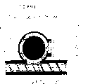
下面,借助附图阐述本发明。在附图中:In the following, the invention is explained with reference to the drawings. In the attached picture:
图1是一个加工装置的局部截面图,其中,该加工滚筒处于径向截面中;Figure 1 is a partial sectional view of a processing device, wherein the processing drum is in radial section;
图2是加工装置之侧视局部截面图,其中,加工滚筒处于纵剖面中;Figure 2 is a side partial sectional view of the processing device, wherein the processing drum is in longitudinal section;
图3是按照图1和2之加工装置的局部俯视图;Figure 3 is a partial top view of the processing device according to Figures 1 and 2;
图4是一个简化的,如在图5所示,按照I-II剖示线通过挤压机管件纵轴线的纵剖图和通过加工滚筒之端部的横截面图。Figure 4 is a simplified longitudinal section through the longitudinal axis of the extruder tube and a cross-section through the end of the processing roll, as shown in Figure 5, along the line I-II.
图5是通过加工滚筒之端部区域的纵剖图和通过挤压机管件的横剖图;Figure 5 is a longitudinal section through the end region of the processing drum and a transverse section through the extruder tube;
图6是通过输送装置,加工滚筒的壳体之垂直剖视图和通过挤压机管件的横截面图;Fig. 6 is a vertical sectional view of the shell of the processing drum and a cross-sectional view of the extruder tube through the conveying device;
该装置包括一个机器壳体1并带一个安装在其上的进料筒12,其下边连接的导引筒14通过一个底板7封闭,而底板7倾斜向下地延伸并于端部连接在该加工装置之一个水平定位的输送管件6的输入开口11上。The device comprises a
在输送管6中可转动地安装了一个水平安置的加工滚筒3,其两侧端被支承在轴承33上并可通过驱动轴35被一个电机34驱动。A
该加工滚筒3包括一个载有刀具的构件17,其上,刀具4径向伸出地沿一圆周螺旋线28被固定;以及包括一个其上连接的载有排料机构的构件18,它的排料机构19由一个螺旋输送器9构成。该输送管件6的输入开口11在轴向20上在该加工滚筒3之整个的载有刀具的构件17范围上伸展并被前壁15和输送漏斗12之两个侧壁16所包围,这些侧壁与底板7构成了输送筒14。The
该底板7可伸达那个在加工滚筒3之回转方向25上看后边安置的开口边缘26处,在该开口边缘上固定一个贯穿该输送开口11的且位置固定的对置刀具5,它伸入到该输送管件6中与加工滚筒3的刀具4啮合切割,其中,在开始切割时,刀具4和对置刀具5的切削刃处在一个平面内。This bottom plate 7 can stretch to the opening edge 26 place that sees rear arrangement on the
在底板7上安置一个在输送开口11的整个长度上延伸的滑板30,它作为送料装置2可由一个液压缸27作用向加工滚筒3运动导送至输送开口11。Arranged on the base plate 7 is a slide 30 extending over the entire length of the
在加工滚筒3的端部区域21中置有一个位于输送管件6的圆周上并朝下指向的排出口10,它同时构成通向挤压螺杆8之管件22的输入口,通过它,这些被粉碎的塑料通过螺旋输送器9进行输送。In the
为此,该挤压螺杆8和螺旋输送器9的轨道是如此配置的,即它们相互间刚好不会接触,因此,可确保一个毫无问题的材料转送。挤压机管件22及加工滚筒3管件的内壁23,24可直接相互相连,其中,两个圆柱管相互透入。而螺旋输送器9和挤压螺杆8的回转方向在输送管6的排出口10处相对于输送方向是相同的指向。该挤压螺杆8的管件22的纵轴线31与加工滚筒3的纵轴线29相互垂直定位。For this purpose, the tracks of the
在输送筒14之底板7上的并要被加工的塑料材料则被受驱动的滑板30朝着加工滚筒3挤送,该加工滚筒3相对于滑板30的运动方向成直角。The plastic material to be processed on the floor 7 of the
借助在加工滚筒3上沿着加工滚筒3上一个圆周螺旋线28分布安置的刀具4和借助随后的螺旋输送器9,使塑料首先被粉碎,然后,在轴向20上通过输送管6被朝着在该输送管6之外壳上的排出口10输送,接着送交给螺杆挤压机。By means of the
在输送管6的内壁24上螺旋形地安置了和转动的刀具4相同之螺旋方向的导向板13,它被用作对应托板用于在通过输送管6输送时改进被粉碎的塑料材料之输送工作。通过使位置固定的对置刀具5按这种方式的结构配置,即在切割过程的开始,运动的刀具4和固定的对置刀具5之刚好啮合的切削刃处于一个和底板7相平行的平面内,则使得位于切削刃之间的间隙在切割过程开始时基本上被消除了,因此,就能实现一个同时的切割作用。On the
为了可以实现一个优化的加工过程,一方面存在的方案是,使被驱动的滑板30对塑料的挤压力,根据挤压螺杆8之电机或加工滚筒3之电机34的功率消耗或电流消耗而加以控制,另一方面存在的方案是,根据塑料在输送管6之排出口10处的温度或者根据挤压螺杆8之电机的功率消耗或电流消耗对加工滚筒3的转数加以调节,依此,可使在输送管6中被粉碎的塑料材料之质量流量保持稳定不变;也不会在排出口10的区域内发生材料积累或者也不会在通向管件22内挤压螺杆8的入口处发生积累,并因此,也不可能导致一个超过该塑料材料之熔化温度的温度升高。In order to realize an optimized processing process, there is a solution on the one hand that the extrusion force of the driven slide plate 30 on the plastic is determined according to the power consumption or current consumption of the
在图4和5中给出的本发明实施例情况下,并在加工滚筒3的端部区域中,与螺旋输送器9相连接地安置一个切割套36,它在刀具托架40上载有回转的刀具37,并且该切割套相对于轴承壳体50在一个压力环39处终止,该压力环39具有一个比加工滚筒3要大的直径并且延伸至输送管6的内壁24附近,并且在该处构成一个狭窄的为0.2至0.4MM的隙缝51并且该压力环39以较小的间距配置在可拆卸的轴承壳体50之端侧面的前面。In the case of the embodiment of the invention given in FIGS. 4 and 5 , and in the end region of the
在切割套36上以两个相邻间距的径向列方式配置了支承托架40,其上固定了这些回转的刀具37;它们在每个径向列中以相互错位180°地被固定在切割套36的外壳上。这两个径向列之相邻的刀具37是相互错位安置的,为的是减小切割时的力峰值。On the cutting
在此,这些回转的刀具37被安置得沿回转方向52看位于前面的刃处于加工滚筒3之径向平面53中。The revolving
这些回转的刀具37相对于固定安装的刀具37’来切割要加工的物料,该刀具37’安置在刀具托架40’上并被定位在一个与加工滚筒3之轴线平行的列中,这些托架40’被固定在一个安装件38上,该安装件(38)通过一个在输送管6之侧面上安置的输入口而被装入并且以螺钉拧住。因此,这些回转的刀具37就与固定的刀具37’在回转方向25上从下往上地相咬合并且在此用侧刃进行切割。These revolving
该输送管6的排出口10构成了在挤压螺杆8之管件22上的输入口并且这回转的刀具37及挤压螺杆8的圆周相互间是几乎接触地靠近的。The
在图6中描述了本发明的一个实施方案,其中,该加工滚筒3的输送管6具有一个中间的朝下的排出口10,它同时构成了该挤压螺杆8之管件22的输入口。An embodiment of the invention is depicted in FIG. 6 , in which the
该输送管构成了一个用于加工滚筒3的壳体41,其设有一个左旋的螺旋输送器42和一个右旋的螺旋输送器43,它们在中间排出口10的两侧配置并在这个开口之前面在加工滚筒3上留出一个中间的区域,其中,沿径向并在圆周上分布地配置填料工具或刀具37。This conveying pipe constitutes a
一个在壳体41长度上的输送开口11朝向上方伸展,这个开口被一个形成加料装置2的烘干容器45所覆盖,该容器45设有一个位于上边的装料装置49并且具有一个侧向的供气源46和一个用于干燥气体的上部出口,该供气源和上部出口与干燥气体的制备装置47相连。A
在烘干容器45中并在位于输送口11上方的区域中安置一个用于烘干的被加热之空气的吹入喷咀44,它通过一管道与一个外部设置的供气源相连接。Arranged in the drying
那些载有相当湿度的空气则在烘干容器45的上部分中通过一个排放管被输送到一个出口48去。The air that is loaded with considerable humidity is delivered to an
供气源46和出口48是用管道连接到一个空气制备装置上的,其中设有净化,烘干和加热措施。
零件编号part number
1机器壳体1 machine shell
2加料装置2 feeding device
3加工滚筒3 processing rollers
4加工滚筒3的刀具4 Tool for machining
5固定的对应刀具5 fixed corresponding tools
6输送管件6 delivery pipe fittings
7底板7 bottom plate
8挤压螺杆8 extrusion screw
9螺旋输送器9 screw conveyor
10输送管6的排出开口10 Discharge opening of
11输送管6的输入开口11 Input opening for
12输送漏斗12 delivery funnel
13螺旋形安装的导向板13 Spiral mounted deflectors
14输送漏斗12的输送筒14 The delivery cylinder of delivery funnel 12
15输送漏斗12的前壁15 the front wall of the delivery funnel 12
16输送漏斗12的侧壁16 The side wall of the delivery funnel 12
17加工滚筒3的载有刀具的部件17 Tool-carrying parts of
18加工滚筒3之载有排料机构的部件18 Parts of the
19在加工滚筒3上的排料机构19 Discharging mechanism on
20输送管6和加工滚筒3的轴向方向20 Axial direction of conveying
21螺旋输送器的端部区域21 End area of the screw conveyor
22挤压螺杆8的管件22 pipe fittings for
23管件22的内壁23 Inner wall of pipe fitting 22
24输送管6的内壁24 the inner wall of
25加工滚筒3的回转方向25 The direction of rotation of the
26输送开口11的开口边缘26 Opening edge of
27滑板30的液压缸27 hydraulic cylinder of slide plate 30
28刀具4的圆周螺旋线Circumferential helix of 28
29加工滚筒3的纵轴线29 longitudinal axis of
30加料装置2的滑板30 slide plate of feeding
31挤压螺杆8之管件22的纵轴线31 The longitudinal axis of the pipe fitting 22 of the
3232
33加工滚筒3的轴承33 Bearing of
34加工滚筒3的电机34 The motor of
35加工滚筒3的驱动轴35 Drive shaft of
36切割套36 cutting sets
37加工滚筒3的回转刀具37 Rotary tool for machining
37’输送管6之固定的刀具Fixed knife for 37'
38用于刀具托架40’的安装件38 Mounts for tool holder 40'
39压力环39 pressure ring
40用于一个回转之刀具37的刀具托架40 Tool holder for a
40’该安装件38的刀具托架40' Tool holder for the
41作为输送管的壳体41 as the housing of the delivery pipe
42左旋的螺旋输送器部分42 left-handed auger section
43右旋的螺旋输送器部分43 right-handed screw conveyor section
44用于干燥的烘干气体如空气的吹入喷咀44 Blow-in nozzles for dry drying gas such as air
45作为加料装置2的烘干容器45 as a drying container for feeding
46用于干燥的烘干气体的供气源46 Gas supply for dry drying gas
47用于烘干气体的制备装置47 Preparation device for drying gas
48载有相当湿度的烘干气体之出口48 Outlet of drying gas containing considerable humidity
49用于烘干容器45的装料装置49 Charging device for drying
50轴承壳体50 bearing housing
51在压力环和输送管6之内壁间的间隙51 The gap between the pressure ring and the inner wall of the
5252
53通过加工滚筒3的轴向平面53 through the axial plane of the
Claims (28)
Applications Claiming Priority (2)
| Application Number | Priority Date | Filing Date | Title |
|---|---|---|---|
| AT1801/96 | 1996-10-14 | ||
| AT0180196A AT407234B (en) | 1996-10-14 | 1996-10-14 | PROCESSING DEVICE FOR CRUSHING AND CONVEYING THERMOPLASTIC PLASTIC MATERIAL |
Publications (2)
| Publication Number | Publication Date |
|---|---|
| CN1233206A CN1233206A (en) | 1999-10-27 |
| CN1086335C true CN1086335C (en) | 2002-06-19 |
Family
ID=3521264
Family Applications (1)
| Application Number | Title | Priority Date | Filing Date |
|---|---|---|---|
| CN97198806A Expired - Lifetime CN1086335C (en) | 1996-10-14 | 1997-10-14 | Processing device for crushing, conveying and plasticizing processing of thermoplastic materials |
Country Status (10)
| Country | Link |
|---|---|
| EP (1) | EP0934144B1 (en) |
| JP (1) | JP4373499B2 (en) |
| KR (1) | KR100551940B1 (en) |
| CN (1) | CN1086335C (en) |
| AT (2) | AT407234B (en) |
| AU (1) | AU6708198A (en) |
| DE (2) | DE19714944A1 (en) |
| ES (1) | ES2216175T3 (en) |
| TR (1) | TR199900792T2 (en) |
| WO (1) | WO1998016360A1 (en) |
Cited By (1)
| Publication number | Priority date | Publication date | Assignee | Title |
|---|---|---|---|---|
| CN105723832A (en) * | 2016-02-22 | 2016-07-06 | 张家港市贝尔机械有限公司 | Film shredder |
Families Citing this family (24)
| Publication number | Priority date | Publication date | Assignee | Title |
|---|---|---|---|---|
| JP4021591B2 (en) * | 1999-07-28 | 2007-12-12 | 萩原工業株式会社 | Recycled pellet manufacturing equipment |
| AT413354B (en) * | 1999-12-27 | 2006-02-15 | Gerold Ing Barth | RECYCLING DEVICE FOR PLASTIC MATERIAL |
| AT412623B (en) * | 2000-04-26 | 2005-05-25 | Bacher Helmut | DEVICE AND METHOD FOR PREPARING THERMOPLASTIC PLASTIC GOODS |
| AT502846A1 (en) * | 2002-07-18 | 2007-06-15 | Starlinger & Co Gmbh | DEVICE FOR PREPARING PLASTIC WASTE |
| AT413512B (en) * | 2003-06-05 | 2006-03-15 | Helmut Bacher | DEVICE FOR PREPARING PLASTIC MATERIAL FOR RECYCLING PURPOSES |
| AT413511B (en) * | 2003-06-05 | 2006-03-15 | Bacher Helmut | DEVICE FOR PREPARING PLASTIC MATERIAL FOR RECYCLING PURPOSES |
| DE102006003529A1 (en) | 2006-01-24 | 2007-08-09 | Herbold Meckesheim Gmbh | Device for crushing parts of any kind |
| AT504326B8 (en) * | 2006-10-30 | 2008-09-15 | Next Generation Recyclingmasch | DEVICE FOR PREPARING THERMOPLASTIC PLASTIC MATERIAL |
| AU2008255616B2 (en) * | 2007-05-25 | 2011-08-18 | Hungry Giant Holdings Pty Ltd | A compacting machine |
| CN103521316B (en) * | 2013-10-22 | 2015-02-18 | 上海申嘉三和环保科技开发有限公司 | Shredding machine with hook-type cutters |
| AT517262A2 (en) * | 2015-06-03 | 2016-12-15 | Next Generation Recyclingmaschinen Gmbh | Processing plant for plastic material |
| AT517756B1 (en) * | 2015-09-22 | 2017-11-15 | Next Generation Recyclingmaschinen Gmbh | Apparatus and method for processing thermoplastic with a blowing device for a screw conveyor |
| AT517972B1 (en) * | 2015-11-24 | 2017-09-15 | Next Generation Recyclingmaschinen Gmbh | Apparatus and method for processing thermoplastic with a tempering device for a screw conveyor |
| CN106826440A (en) * | 2016-12-25 | 2017-06-13 | 重庆宜居门业有限公司 | Timber sanding apparatus |
| US11559947B2 (en) * | 2017-03-30 | 2023-01-24 | Hewlett-Packard Development Company, L.P. | Build material conveyors |
| AT522051B1 (en) | 2018-12-19 | 2021-04-15 | Next Generation Recyclingmaschinen Gmbh | Processing plant and process for processing plastic material for its recycling |
| AT523082B1 (en) | 2019-10-16 | 2022-07-15 | Pureloop Gesmbh | Device for processing material, in particular plastic material |
| CN112049372B (en) * | 2020-08-25 | 2022-07-22 | 河南七彩异涂新材料科技有限公司 | Wall putty powder advances whitewashed equipment of whitewashing by oneself for building |
| CN112871085B (en) * | 2021-01-13 | 2022-10-21 | 诸城外贸有限责任公司 | Poultry is bred pelletization equipment for medicine production |
| CN113733512A (en) * | 2021-09-14 | 2021-12-03 | 南京弘威橡塑机械配件有限公司 | High-speed single-double screw mixing extruder |
| CN114082496A (en) * | 2021-10-16 | 2022-02-25 | 怀化市酱香和农业科技股份有限公司 | Chop hot pepper comminution device for chilli production |
| CN115284495B (en) * | 2022-07-06 | 2024-06-21 | 青岛科技大学 | Plastic waste crushing device and method |
| CN116620749A (en) * | 2023-07-11 | 2023-08-22 | 昆山市御景轩园林工程有限公司 | A device and method for collecting landscaping waste |
| AT527439A1 (en) | 2023-08-01 | 2025-02-15 | Next Generation Recyclingmaschinen Gmbh | processing plant for plastic material |
Citations (2)
| Publication number | Priority date | Publication date | Assignee | Title |
|---|---|---|---|---|
| WO1993025312A1 (en) * | 1992-06-12 | 1993-12-23 | Erema Engineering Recycling Maschinen Und Anlagen Gesellschaft M.B.H. | Device for plasticising thermoplastic material |
| US5462238A (en) * | 1994-03-17 | 1995-10-31 | Guaranteed Baffle Co., Inc. | Apparatus and method for shredding insulation |
Family Cites Families (11)
| Publication number | Priority date | Publication date | Assignee | Title |
|---|---|---|---|---|
| DE2842162A1 (en) * | 1978-09-28 | 1980-04-17 | Anton Kolb Maschinenbau | Thermoplastics scrap recovery plant - having material macerated by counter-rotating profiled rollers and passing to consolidating screw and final extruders |
| DE3020908A1 (en) * | 1980-06-02 | 1981-12-10 | Nolting, Herbert, Ing.(grad.), 4930 Detmold | Fire-wood comminuter and feed storage unit - has pipe encasing conveyor worm-gear leaving side-wall near cutter worm-gear |
| JPS6310253Y2 (en) * | 1985-09-02 | 1988-03-28 | ||
| EP0390873B1 (en) * | 1988-02-05 | 1992-05-20 | EREMA Engineering Recycling Maschinen und Anlagen Gesellschaft m.b.H. | Device for processing thermoplastics |
| JPH065852Y2 (en) * | 1989-02-10 | 1994-02-16 | 駿河精機株式会社 | Foam plastic volume reduction machine |
| JPH0628245Y2 (en) * | 1990-06-08 | 1994-08-03 | 駿河精機株式会社 | Volume reduction equipment for waste foamed resin |
| EP0514327A1 (en) * | 1991-05-07 | 1992-11-19 | Kueny Maschinenbau | Shredding apparatus for wood, metal parts, refuse and other waste |
| US5289978A (en) * | 1991-07-08 | 1994-03-01 | Lundquist Lynn C | Apparatus for continuous container label removal |
| US5425507A (en) * | 1993-03-03 | 1995-06-20 | Stumpff; Roger | Method and apparatus for comminuting materials |
| AU676108B2 (en) * | 1993-12-21 | 1997-02-27 | Helmut Bacher | Device for processing thermoplastic materials |
| JPH09234386A (en) * | 1996-02-28 | 1997-09-09 | Toyota Motor Corp | Paint lees feeder |
-
1996
- 1996-10-14 AT AT0180196A patent/AT407234B/en not_active IP Right Cessation
-
1997
- 1997-04-10 DE DE19714944A patent/DE19714944A1/en not_active Ceased
- 1997-10-14 EP EP19970948759 patent/EP0934144B1/en not_active Expired - Lifetime
- 1997-10-14 ES ES97948759T patent/ES2216175T3/en not_active Expired - Lifetime
- 1997-10-14 JP JP51802198A patent/JP4373499B2/en not_active Expired - Fee Related
- 1997-10-14 DE DE59711500T patent/DE59711500D1/en not_active Expired - Lifetime
- 1997-10-14 AT AT97948759T patent/ATE263664T1/en active
- 1997-10-14 AU AU67081/98A patent/AU6708198A/en not_active Abandoned
- 1997-10-14 WO PCT/EP1997/005649 patent/WO1998016360A1/en not_active Ceased
- 1997-10-14 CN CN97198806A patent/CN1086335C/en not_active Expired - Lifetime
- 1997-10-14 TR TR1999/00792T patent/TR199900792T2/en unknown
- 1997-10-14 KR KR1019997003217A patent/KR100551940B1/en not_active Expired - Lifetime
Patent Citations (2)
| Publication number | Priority date | Publication date | Assignee | Title |
|---|---|---|---|---|
| WO1993025312A1 (en) * | 1992-06-12 | 1993-12-23 | Erema Engineering Recycling Maschinen Und Anlagen Gesellschaft M.B.H. | Device for plasticising thermoplastic material |
| US5462238A (en) * | 1994-03-17 | 1995-10-31 | Guaranteed Baffle Co., Inc. | Apparatus and method for shredding insulation |
Cited By (2)
| Publication number | Priority date | Publication date | Assignee | Title |
|---|---|---|---|---|
| CN105723832A (en) * | 2016-02-22 | 2016-07-06 | 张家港市贝尔机械有限公司 | Film shredder |
| CN105723832B (en) * | 2016-02-22 | 2017-07-21 | 江苏贝尔机械有限公司 | Film shredder |
Also Published As
| Publication number | Publication date |
|---|---|
| AT407234B (en) | 2001-01-25 |
| EP0934144A1 (en) | 1999-08-11 |
| KR100551940B1 (en) | 2006-02-20 |
| JP2001504400A (en) | 2001-04-03 |
| DE59711500D1 (en) | 2004-05-13 |
| ATA180196A (en) | 2000-06-15 |
| WO1998016360A1 (en) | 1998-04-23 |
| ATE263664T1 (en) | 2004-04-15 |
| ES2216175T3 (en) | 2004-10-16 |
| CN1233206A (en) | 1999-10-27 |
| JP4373499B2 (en) | 2009-11-25 |
| EP0934144B1 (en) | 2004-04-07 |
| AU6708198A (en) | 1998-05-11 |
| TR199900792T2 (en) | 1999-09-21 |
| DE19714944A1 (en) | 1998-04-16 |
| KR20000049131A (en) | 2000-07-25 |
Similar Documents
| Publication | Publication Date | Title |
|---|---|---|
| CN1233206A (en) | Processing device for crushing, conveying and plasticizing processing of thermoplastic materials | |
| AU2004245126B2 (en) | Device for preparation of plastic materials for recycling purposes | |
| CN103874565B (en) | For the device for being pre-processed to synthetic material and then conveying, plastify or coalesce | |
| CN103857503B (en) | For the device for reclaiming purpose to synthetic material pretreatment and convey, plastify or coalesce | |
| AU2004245128B2 (en) | Device for the preparation of plastics material for recycling purposes | |
| CN103874566B (en) | Apparatus for processing plastic material | |
| US6126100A (en) | Processing device for crushing, conveying and plastifying thermoplastic synthetic material | |
| CN210759079U (en) | Extruder for plastic film | |
| KR101309975B1 (en) | Apparatus for kneading and extruding functional resin produced therefrom | |
| CN118451934B (en) | Straw crushing device | |
| CN220936692U (en) | Pet feed pelletization drying device | |
| CN204076565U (en) | A kind of natural rubber mixing is dry stirs production line | |
| CN111361044A (en) | Plastic extrusion granulator | |
| CN110281410A (en) | A kind of Wood plastic composite production raw material proportioning equipment | |
| CN211763331U (en) | Double-screw extruder for plastic modification | |
| JP2005324522A (en) | Thermoplastic polymer piece volume reduction device | |
| CN208789042U (en) | Compression bin film feeding device | |
| CN113681775A (en) | Plastic grinder with multi-stage grinding mechanism | |
| CN223478086U (en) | A double screw extrusion feeding device for shredded plastic recycling silo | |
| CN219768788U (en) | Double-order extrusion granulator with uniform feeding function | |
| CN223463613U (en) | Feed pelletizing machine for feed production | |
| CN221863669U (en) | Forage machine for livestock-raising | |
| CN219667398U (en) | Double-screw sheet production equipment | |
| CN215826040U (en) | Coal rod extruder | |
| CN210389757U (en) | Modified plastic particle production line |
Legal Events
| Date | Code | Title | Description |
|---|---|---|---|
| C06 | Publication | ||
| PB01 | Publication | ||
| C10 | Entry into substantive examination | ||
| SE01 | Entry into force of request for substantive examination | ||
| CI02 | Correction of invention patent application |
Correction item: Co-applicant Correct: The third man:Kroiss Guenter False: Third people missing Number: 43 Page: The title page Volume: 15 |
|
| COR | Change of bibliographic data |
Free format text: CORRECT: CO-APPLICANT; FROM: LACK NO. 3 PERSONAL TO: NO. 3 INDIVIDUALS: BEIJING TEKELUOYISHI |
|
| ERR | Gazette correction |
Free format text: CORRECT: CO-APPLICANT; BEIJING TEKELUOYISHI |
|
| C14 | Grant of patent or utility model | ||
| GR01 | Patent grant | ||
| ASS | Succession or assignment of patent right |
Owner name: NEXT GENERATION RENEWABLE MACHINE CO., LTD. Free format text: FORMER OWNER: BARTH GEROLD; MANFRED. DOBERSBERGER; BEIJING TEKELUOYISHI Effective date: 20071102 Owner name: BARTH GEROLD; MANFRED. DOBERSBERGER; BEIJING TEKE Free format text: FORMER OWNER: BARTH GEROLD; MANFRED. DOBERSBERGER; FELLINGER MARKUS; BEIJING TEKELUOYISHI Effective date: 20071102 |
|
| C41 | Transfer of patent application or patent right or utility model | ||
| TR01 | Transfer of patent right |
Effective date of registration: 20071102 Address after: Austria Ma Hitler lunk Patentee after: Next generation regenerative Machinery Co.,Ltd. Address before: Will Austria Haiying Co-patentee before: Dobersberge. Manfred Patentee before: Gerold Barth Co-patentee before: Gent Croix Effective date of registration: 20071102 Address after: Will Austria Haiying Co-patentee after: Dobersberge. Manfred Patentee after: Gerold Barth Co-patentee after: Gent Croix Address before: Will Austria Haiying Co-patentee before: Dobersberge. Manfred Patentee before: Gerold Barth Co-patentee before: Fellinger Markus Co-patentee before: Gent Croix |
|
| CX01 | Expiry of patent term |
Granted publication date: 20020619 |
|
| CX01 | Expiry of patent term |