CN108580725B - Automatic waste collecting device for hardware punching machine and using method thereof - Google Patents
Automatic waste collecting device for hardware punching machine and using method thereof Download PDFInfo
- Publication number
- CN108580725B CN108580725B CN201810323065.8A CN201810323065A CN108580725B CN 108580725 B CN108580725 B CN 108580725B CN 201810323065 A CN201810323065 A CN 201810323065A CN 108580725 B CN108580725 B CN 108580725B
- Authority
- CN
- China
- Prior art keywords
- waste
- stamping
- rod
- die
- collecting device
- Prior art date
- Legal status (The legal status is an assumption and is not a legal conclusion. Google has not performed a legal analysis and makes no representation as to the accuracy of the status listed.)
- Active
Links
- 239000002699 waste material Substances 0.000 title claims abstract description 110
- 238000004080 punching Methods 0.000 title claims abstract description 59
- 238000000034 method Methods 0.000 title claims abstract description 13
- 230000005540 biological transmission Effects 0.000 claims abstract description 53
- 238000011084 recovery Methods 0.000 claims abstract description 20
- 238000005299 abrasion Methods 0.000 claims abstract description 10
- 239000004973 liquid crystal related substance Substances 0.000 claims abstract description 7
- 238000004064 recycling Methods 0.000 claims description 16
- 239000003921 oil Substances 0.000 claims description 15
- 239000010720 hydraulic oil Substances 0.000 claims description 12
- 239000002994 raw material Substances 0.000 claims description 8
- 229910052751 metal Inorganic materials 0.000 claims 1
- 239000002184 metal Substances 0.000 claims 1
- 150000002739 metals Chemical class 0.000 claims 1
- 238000004519 manufacturing process Methods 0.000 abstract description 2
- 239000000203 mixture Substances 0.000 abstract description 2
- 230000002035 prolonged effect Effects 0.000 description 3
- 238000000926 separation method Methods 0.000 description 3
- XEEYBQQBJWHFJM-UHFFFAOYSA-N Iron Chemical compound [Fe] XEEYBQQBJWHFJM-UHFFFAOYSA-N 0.000 description 2
- 238000010586 diagram Methods 0.000 description 2
- RYGMFSIKBFXOCR-UHFFFAOYSA-N Copper Chemical compound [Cu] RYGMFSIKBFXOCR-UHFFFAOYSA-N 0.000 description 1
- XAGFODPZIPBFFR-UHFFFAOYSA-N aluminium Chemical compound [Al] XAGFODPZIPBFFR-UHFFFAOYSA-N 0.000 description 1
- 229910052782 aluminium Inorganic materials 0.000 description 1
- 238000005452 bending Methods 0.000 description 1
- 230000009286 beneficial effect Effects 0.000 description 1
- 229910052802 copper Inorganic materials 0.000 description 1
- 239000010949 copper Substances 0.000 description 1
- 229910052742 iron Inorganic materials 0.000 description 1
- 238000012986 modification Methods 0.000 description 1
- 230000004048 modification Effects 0.000 description 1
- 238000000465 moulding Methods 0.000 description 1
- 229910001220 stainless steel Inorganic materials 0.000 description 1
- 239000010935 stainless steel Substances 0.000 description 1
Images



Classifications
-
- B—PERFORMING OPERATIONS; TRANSPORTING
- B21—MECHANICAL METAL-WORKING WITHOUT ESSENTIALLY REMOVING MATERIAL; PUNCHING METAL
- B21D—WORKING OR PROCESSING OF SHEET METAL OR METAL TUBES, RODS OR PROFILES WITHOUT ESSENTIALLY REMOVING MATERIAL; PUNCHING METAL
- B21D43/00—Feeding, positioning or storing devices combined with, or arranged in, or specially adapted for use in connection with, apparatus for working or processing sheet metal, metal tubes or metal profiles; Associations therewith of cutting devices
- B21D43/20—Storage arrangements; Piling or unpiling
-
- B—PERFORMING OPERATIONS; TRANSPORTING
- B21—MECHANICAL METAL-WORKING WITHOUT ESSENTIALLY REMOVING MATERIAL; PUNCHING METAL
- B21D—WORKING OR PROCESSING OF SHEET METAL OR METAL TUBES, RODS OR PROFILES WITHOUT ESSENTIALLY REMOVING MATERIAL; PUNCHING METAL
- B21D37/00—Tools as parts of machines covered by this subclass
- B21D37/14—Particular arrangements for handling and holding in place complete dies
-
- Y—GENERAL TAGGING OF NEW TECHNOLOGICAL DEVELOPMENTS; GENERAL TAGGING OF CROSS-SECTIONAL TECHNOLOGIES SPANNING OVER SEVERAL SECTIONS OF THE IPC; TECHNICAL SUBJECTS COVERED BY FORMER USPC CROSS-REFERENCE ART COLLECTIONS [XRACs] AND DIGESTS
- Y02—TECHNOLOGIES OR APPLICATIONS FOR MITIGATION OR ADAPTATION AGAINST CLIMATE CHANGE
- Y02P—CLIMATE CHANGE MITIGATION TECHNOLOGIES IN THE PRODUCTION OR PROCESSING OF GOODS
- Y02P70/00—Climate change mitigation technologies in the production process for final industrial or consumer products
- Y02P70/10—Greenhouse gas [GHG] capture, material saving, heat recovery or other energy efficient measures, e.g. motor control, characterised by manufacturing processes, e.g. for rolling metal or metal working
Landscapes
- Engineering & Computer Science (AREA)
- Mechanical Engineering (AREA)
- Processing Of Solid Wastes (AREA)
- Press Drives And Press Lines (AREA)
Abstract
The invention discloses an automatic waste collecting device for a hardware punching machine and a using method of the automatic waste collecting device, and the automatic waste collecting device comprises a bottom fixing seat, a waste conveying belt, a pushing hydraulic cylinder, an upper punching die and a connecting rod transmission mechanism, wherein the waste conveying belt is arranged above the bottom fixing seat, a waste recovery box is arranged on one side of the waste conveying belt, an anti-abrasion lining plate is arranged in the waste recovery box, a connecting shaft rod is arranged below an electromagnet controller, a fixed connecting rod is arranged above an auxiliary transmission rod, a transmission driving motor is arranged on the other side of a main support leg, an operation control box is arranged below the transmission driving motor, and a liquid crystal operation screen is arranged above the operation control box. Has the advantages that: the waste material after can be automatically retrieved the punching press, can carry out altitude mixture control to punching press lower die according to the demand simultaneously, can quick replacement to punching press lower die, has improved punching press efficiency greatly, has reduced manufacturing cost.
Description
Technical Field
The invention relates to the field of hardware punching machine equipment, in particular to an automatic waste collecting device for a hardware punching machine and a using method thereof.
Background
The hardware stamping is a process for deforming or breaking stainless steel, iron, aluminum, copper and other plates by using a punch press and a die to achieve a certain shape and size. Hardware stamping is sometimes referred to as sheet forming, but with some differences. The sheet molding is performed by using a sheet, a thin pipe, a thin profile, or the like as a raw material. The forming method of plastic working is generally called plate forming, and in this case, deformation in the direction of a thick plate is not generally considered. The stamping process can be roughly divided into two major types, namely, a separation step and a forming step (bending, drawing and forming). The separation process is that the stamping part and the blank are separated from each other along a certain contour line in the stamping process, and meanwhile, the quality of the separation section of the stamping part also meets a certain requirement; the forming process is to make the punching blank generate plastic deformation under the condition of not damaging, and convert the punching blank into the required finished product shape, and simultaneously meet the requirements of dimensional tolerance and the like.
At present, most of hardware punching machines used in China are manual to take out waste materials after punching, so that the working efficiency is low, and a large amount of human resources are wasted.
Disclosure of Invention
The invention aims to solve the problems and provide an automatic waste collecting device for a hardware punching machine and a using method thereof.
The invention realizes the purpose through the following technical scheme:
an automatic waste collecting device for a hardware punching machine comprises a bottom fixing seat, a waste conveying belt, a pushing hydraulic cylinder, a punching upper die and a connecting rod transmission mechanism, wherein the waste conveying belt is arranged above the bottom fixing seat, a waste recovery box is arranged on one side of the waste conveying belt, an anti-abrasion lining plate is arranged in the waste recovery box, an electromagnet controller is arranged in the anti-abrasion lining plate, a connecting shaft rod is arranged below the electromagnet controller, an electromagnet is arranged below the connecting shaft rod, a capacity inductor is arranged below the electromagnet, the pushing hydraulic cylinder is arranged above the waste conveying belt, a telescopic hydraulic rod is arranged above the pushing hydraulic cylinder, a punching lower die is arranged above the telescopic hydraulic rod, the punching upper die is arranged above the punching lower die, and an upper die controller is arranged above the punching upper die, go up mould controller one side and install the main tributary supporting leg, install main tributary supporting leg one side link transmission mechanism, the punching press pneumatic cylinder is installed to link transmission mechanism top, hydraulic pressure oil pipe is installed to punching press pneumatic cylinder below, the oil pipe mount is installed to hydraulic pressure oil pipe below, main drive connecting rod is installed to oil pipe mount below, the direction regulation head is installed to main drive connecting rod below, the auxiliary transmission pole is installed to direction regulation head top, install the auxiliary transmission pole top fixed link.
Furthermore, the bottom fixing seat is connected with the waste conveying belt through a bolt, and the waste conveying belt is connected with the waste recycling bin through a bolt.
Furthermore, the anti-abrasion lining plate is connected with the waste recycling bin in a nested manner, the electromagnet controller is fixed to the top of the inner wall of the waste recycling bin through bolts, the electromagnet controller is connected with the connecting shaft rod through a shaft sleeve, the connecting shaft rod is connected with the electromagnet through a bolt, and the capacity inductor is connected with the operation control box through a wire.
Furthermore, the pushing hydraulic cylinder is connected with the telescopic hydraulic rod in a nested mode, and the telescopic hydraulic rod is connected with the lower stamping die through a bolt.
Furthermore, the stamping upper die is connected with the upper die controller through a shaft, and the main support leg is connected with the transmission driving motor through a bolt.
Furthermore, the lower stamping die is welded with the fixed connecting rod, the fixed connecting rod is connected with the auxiliary transmission rod through a pin shaft, the auxiliary transmission rod is connected with the direction adjusting head through a pin shaft, the main transmission connecting rod is connected with the oil pipe fixing frame through a shaft, the oil pipe fixing frame is connected with the hydraulic oil pipe in a clamping mode, and the hydraulic oil pipe is connected with the stamping hydraulic cylinder through a bolt.
Furthermore, the middle part of the lower stamping die is of a hollow structure.
Further, the transmission driving motor is connected with the operation control box through a lead.
Furthermore, the operation control box is connected with the liquid crystal operation screen through a wire.
The invention also provides an automatic waste collecting method for the hardware punching machine, which is applied to the automatic waste collecting device for the hardware punching machine, punching raw materials are placed above a lower punching die, the upper punching die is pushed by a punching hydraulic cylinder to move to punch the raw materials, the upper punching die is controlled by an upper die controller, the punched waste materials flow out of the lower punching die and enter a waste conveying belt, the conveying driving motor drives the waste conveying belt to move to convey the waste materials into a waste material recycling box, an anti-abrasion lining plate prevents the waste materials from wearing the interior of the waste material recycling box, the service life of the waste material recycling box is prolonged, the electromagnet controller controls the electromagnet, the connecting shaft rod connects and fixes the electromagnet, and the capacity inductor induces the capacity in the waste material recycling box, when the die is replaced, the main transmission connecting rod drives the auxiliary transmission rod to move, so that one end of the lower stamping die is jacked up by the fixed connecting rod, the lower stamping die is replaced, and the operation control box is used for operating and controlling the device.
The invention has the beneficial effects that:
1. the waste conveyor belt and the waste recovery box are arranged, so that the punched waste can be automatically recovered;
2. the abrasion-proof inner lining plate is arranged, so that the waste can be effectively prevented from abrading the interior of the waste recovery box, and the service life of the waste recovery box is prolonged;
3. through setting up the main drive connecting rod, can carry out altitude mixture control to punching press bed die according to the demand, can quick replacement to punching press bed die, improve punching press efficiency greatly, reduce manufacturing cost.
Drawings
FIG. 1 is a schematic front view of an automatic waste collecting device for a hardware punching machine according to the present invention;
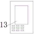
FIG. 2 is a schematic diagram of an appearance structure of an operation control box of the automatic waste material collecting device for the hardware punching machine, provided by the invention;
FIG. 3 is a schematic diagram of a front view of a waste recycling bin of an automatic waste collecting device for a hardware punching machine according to the present invention;
FIG. 4 is a schematic front view of a connecting rod transmission mechanism of an automatic waste collecting device for a hardware punching machine according to the present invention.
The reference numerals are explained below:
1. a bottom fixed seat; 2. a waste conveyor; 3. a waste recovery tank; 301. an anti-wear lining plate; 302. an electromagnet controller; 303. connecting the shaft lever; 304. an electromagnet; 305. a capacity sensor; 4. pushing the hydraulic cylinder; 5. a telescopic hydraulic rod; 6. stamping a lower die; 7. stamping an upper die; 8. an upper die controller; 9. a main support leg; 10. a link transmission mechanism; 1001. a stamping hydraulic cylinder; 1002. a hydraulic oil pipe; 1003. an oil pipe fixing frame; 1004. a main drive link; 1005. a direction adjusting head; 1006. an auxiliary transmission rod; 1007. fixing the connecting rod; 11. a conveyance drive motor; 12. operating the control box; 13. and a liquid crystal operation screen.
Detailed Description
The invention will be further described with reference to the accompanying drawings in which:
as shown in fig. 1-4, an automatic waste collecting device for a hardware punching machine comprises a bottom fixing seat 1, a waste conveying belt 2, a pushing hydraulic cylinder 4, a punching upper die 7 and a connecting rod transmission mechanism 10, wherein the waste conveying belt 2 is arranged above the bottom fixing seat 1, the waste conveying belt 2 conveys punched waste, a waste recycling box 3 is installed on one side of the waste conveying belt 2, the waste recycling box 3 recycles and places the punched waste, an anti-abrasion lining plate 301 is installed inside the waste recycling box 3, an electromagnet controller 302 is installed inside the anti-abrasion lining plate 301, a connecting shaft rod 303 is installed below the electromagnet controller 302, an electromagnet 304 is installed below the connecting shaft rod 303, a capacity inductor 305 is installed below the electromagnet 304, the pushing hydraulic cylinder 4 is arranged above the waste conveying belt 2, a telescopic hydraulic rod 5 is arranged above the pushing hydraulic cylinder 4, a lower stamping die 6 is arranged above the telescopic hydraulic rod 5, an upper stamping die 7 is arranged above the lower stamping die 6, the upper stamping die 7 and the lower stamping die 6 stamp raw materials, an upper die controller 8 is arranged above the upper stamping die 7, a main support leg 9 is arranged on one side of the upper die controller 8, the link transmission mechanism 10 is arranged on one side of the main support leg 9, the link transmission mechanism 10 jacks the lower stamping die 6, a stamping hydraulic cylinder 1001 is arranged above the link transmission mechanism 10, a hydraulic oil pipe 1002 is arranged below the stamping hydraulic oil pipe 1001, an oil pipe fixing frame 1003 is arranged below the hydraulic oil pipe 1002, a main transmission connecting rod 1004 is arranged below the oil pipe fixing frame 1003, a direction adjusting head 1005 is arranged below the main transmission connecting rod 1004, an auxiliary transmission rod 1006 is installed above the direction adjusting head 1005, the fixed connecting rod 1007 is installed above the auxiliary transmission rod 1006, a transmission driving motor 11 is installed on the other side of the main supporting leg 9, the transmission driving motor 11 provides power for the work of the waste conveying belt 2, an operation control box 12 is installed below the transmission driving motor 11, and a liquid crystal operation screen 13 is installed above the operation control box 12.
In this embodiment, the bottom fixing seat 1 is connected to the waste conveyor belt 2 through a bolt, and the waste conveyor belt 2 is connected to the waste recycling bin 3 through a bolt.
In this embodiment, the anti-wear lining plate 301 is connected to the waste recycling bin 3 in a nested manner, the electromagnet controller 302 is fixed to the top of the inner wall of the waste recycling bin 3 by bolts, the electromagnet controller 302 is connected to the connecting shaft rod 303 by a shaft sleeve, the connecting shaft rod 303 is connected to the electromagnet 304 by bolts, and the capacity sensor 305 is connected to the operation control bin 12 by a wire.
In this embodiment, the pushing hydraulic cylinder 4 is connected to the telescopic hydraulic rod 5 in a nested manner, and the telescopic hydraulic rod 5 is connected to the lower stamping die 6 through a bolt.
In this embodiment, the upper stamping die 7 and the upper die controller 8 are connected through a shaft, and the main support leg 9 and the transmission driving motor 11 are connected through a bolt.
In this embodiment, the lower stamping die 6 is welded to the fixed link 1007, the fixed link 1007 is connected to the auxiliary transmission rod 1006 through a pin, the auxiliary transmission rod 1006 is connected to the direction adjusting head 1005 through a pin, the main transmission link 1004 is connected to the oil pipe fixing frame 1003 through a shaft, the oil pipe fixing frame 1003 is connected to the hydraulic oil pipe 1002 in a snap-fit manner, and the hydraulic oil pipe 1002 is connected to the stamping hydraulic cylinder 1001 through a bolt.
In this embodiment, the middle portion of the lower stamping die 6 is a hollow structure.
In this embodiment, the transmission driving motor 11 is connected to the operation control box 12 through a wire.
In this embodiment, the operation control box 12 is connected to the liquid crystal operation panel 13 through a wire.
The invention also provides an automatic waste collecting method for the hardware punching machine, which is applied to the automatic waste collecting device for the hardware punching machine, punching raw materials are placed above a lower punching die 6, the upper punching die 7 is pushed by a punching hydraulic cylinder 1001 to move to punch the raw materials, the upper die controller 8 controls the upper punching die 7, the punched waste flows out of the lower punching die 6 and enters the waste conveyor belt 2, the conveying driving motor 11 drives the waste conveyor belt 2 to move to convey the waste into the waste recovery box 3, the wear-resistant lining plate 301 prevents the waste from wearing the interior of the waste recovery box 3, the service life of the waste recovery box is prolonged, the electromagnet controller 302 controls the electromagnet 304, the connecting shaft rod 303 connects and fixes the electromagnet 304, and the capacity inductor 305 induces the capacity in the waste recovery box 3, when the die is replaced, the main transmission link 1004 drives the auxiliary transmission rod 1006 to move, so that the fixed link 1007 jacks up one end of the lower stamping die 6 to replace the lower stamping die 6, and the operation control box 12 controls the operation of the device.
The foregoing illustrates and describes the principles, general features, and advantages of the present invention. It will be understood by those skilled in the art that the present invention is not limited to the embodiments described above, which are described in the specification and illustrated only to illustrate the principle of the present invention, but that various changes and modifications may be made therein without departing from the spirit and scope of the present invention, which fall within the scope of the invention as claimed.
Claims (10)
1. The utility model provides a five metals is automatic collection waste material device for punching machine which characterized in that: the waste material recovery device comprises a bottom fixing seat (1), a waste material conveying belt (2), a pushing hydraulic cylinder (4), an upper stamping die (7) and a connecting rod transmission mechanism (10), wherein the waste material conveying belt (2) is arranged above the bottom fixing seat (1), a waste material recovery box (3) is installed on one side of the waste material conveying belt (2), an anti-abrasion lining plate (301) is installed inside the waste material recovery box (3), an electromagnet controller (302) is installed inside the anti-abrasion lining plate (301), a connecting shaft rod (303) is installed below the electromagnet controller (302), an electromagnet (304) is installed below the connecting shaft rod (303), a capacity inductor (305) is installed below the electromagnet (304), the pushing hydraulic cylinder (4) is arranged above the waste material conveying belt (2), and a telescopic hydraulic rod (5) is arranged above the pushing hydraulic cylinder (4), the stamping lower die (6) is installed above the telescopic hydraulic rod (5), the stamping upper die (7) is installed above the stamping lower die (6), the stamping upper die (7) is installed above the upper die controller (8), the main support leg (9) is installed on one side of the upper die controller (8), the connecting rod transmission mechanism (10) is installed on one side of the main support leg (9), the stamping hydraulic cylinder (1001) is installed above the connecting rod transmission mechanism (10), the hydraulic oil pipe (1002) is installed below the stamping hydraulic cylinder (1001), the oil pipe fixing frame (1003) is installed below the hydraulic oil pipe (1002), the main transmission connecting rod (1004) is installed below the oil pipe fixing frame (1003), the direction 1005 adjusting head (1005) is installed below the main transmission connecting rod (1004), and the auxiliary transmission rod (1006) is installed above the direction adjusting head (1005), the fixed connecting rod (1007) is installed above the auxiliary transmission rod (1006), the transmission driving motor (11) is installed on the other side of the main supporting leg (9), the operation control box (12) is installed below the transmission driving motor (11), and the liquid crystal operation screen (13) is installed above the operation control box (12);
the main transmission connecting rod (1004) drives the auxiliary transmission rod (1006) to move, so that one end of the lower stamping die (6) is jacked up by the fixed connecting rod (1007), the lower stamping die (6) is replaced, and the operation control box (12) is used for operating and controlling the device.
2. The automatic waste collecting device for the hardware punching machine, according to claim 1, is characterized in that: the bottom fixing seat (1) is connected with the waste conveying belt (2) through bolts, and the waste conveying belt (2) is connected with the waste recovery box (3) through bolts.
3. The automatic waste collecting device for the hardware punching machine, according to claim 1, is characterized in that: the anti-abrasion inner lining plate (301) is connected with the waste recycling box (3) in a nested mode, the electromagnet controller (302) is fixed to the top of the inner wall of the waste recycling box (3) through bolts, the electromagnet controller (302) is connected with the connecting shaft rod (303) through a shaft sleeve, the connecting shaft rod (303) is connected with the electromagnet (304) through bolts, and the capacity inductor (305) is connected with the operation control box (12) through a lead.
4. The automatic waste collecting device for the hardware punching machine, according to claim 1, is characterized in that: the pushing hydraulic cylinder (4) is connected with the telescopic hydraulic rod (5) in a nested mode, and the telescopic hydraulic rod (5) is connected with the lower stamping die (6) through bolts.
5. The automatic waste collecting device for the hardware punching machine, according to claim 1, is characterized in that: the stamping upper die (7) is connected with the upper die controller (8) through a shaft, and the main supporting legs (9) are connected with the transmission driving motor (11) through bolts.
6. The automatic waste collecting device for the hardware punching machine, according to claim 1, is characterized in that: the stamping lower die (6) is welded with the fixed connecting rod (1007), the fixed connecting rod (1007) is connected with the auxiliary transmission rod (1006) through a pin shaft, the auxiliary transmission rod (1006) is connected with the direction adjusting head (1005) through a pin shaft, the main transmission connecting rod (1004) is connected with the oil pipe fixing frame (1003) through a shaft, the oil pipe fixing frame (1003) is connected with the hydraulic oil pipe (1002) in a clamping mode, and the hydraulic oil pipe (1002) is connected with the stamping hydraulic cylinder (1001) through a bolt.
7. The automatic waste collecting device for the hardware punching machine, according to claim 1, is characterized in that: the middle part of the lower stamping die (6) is of a hollow structure.
8. The automatic waste collecting device for the hardware punching machine, according to claim 1, is characterized in that: the transmission driving motor (11) is connected with the operation control box (12) through a lead.
9. The automatic waste collecting device for the hardware punching machine, according to claim 1, is characterized in that: the operation control box (12) is connected with the liquid crystal operation screen (13) through a lead.
10. An automatic waste collecting method for a hardware punching machine is applied to the automatic waste collecting device for the hardware punching machine, which is characterized in that: stamping raw materials are placed above a lower stamping die (6), a stamping hydraulic cylinder (1001) pushes an upper stamping die (7) to move to stamp the raw materials, an upper die controller (8) controls the upper stamping die (7), waste materials after stamping flow out of the lower stamping die (6) and enter a waste material conveyor belt (2), a conveying driving motor (11) drives the waste material conveyor belt (2) to move and send the waste materials into a waste material recovery box (3), an abrasion-proof lining plate (301) prevents the waste materials from abrading the interior of the waste material recovery box (3) and prolongs the service life of the waste material recovery box, an electromagnet controller (302) controls an electromagnet (304), a connecting shaft lever (303) connects and fixes the electromagnet (304), and a capacity inductor (305) induces the capacity in the waste material recovery box (3), when the mold is replaced.
Priority Applications (1)
| Application Number | Priority Date | Filing Date | Title |
|---|---|---|---|
| CN201810323065.8A CN108580725B (en) | 2018-04-11 | 2018-04-11 | Automatic waste collecting device for hardware punching machine and using method thereof |
Applications Claiming Priority (1)
| Application Number | Priority Date | Filing Date | Title |
|---|---|---|---|
| CN201810323065.8A CN108580725B (en) | 2018-04-11 | 2018-04-11 | Automatic waste collecting device for hardware punching machine and using method thereof |
Publications (2)
| Publication Number | Publication Date |
|---|---|
| CN108580725A CN108580725A (en) | 2018-09-28 |
| CN108580725B true CN108580725B (en) | 2020-04-03 |
Family
ID=63622026
Family Applications (1)
| Application Number | Title | Priority Date | Filing Date |
|---|---|---|---|
| CN201810323065.8A Active CN108580725B (en) | 2018-04-11 | 2018-04-11 | Automatic waste collecting device for hardware punching machine and using method thereof |
Country Status (1)
| Country | Link |
|---|---|
| CN (1) | CN108580725B (en) |
Families Citing this family (4)
| Publication number | Priority date | Publication date | Assignee | Title |
|---|---|---|---|---|
| CN109605472B (en) * | 2018-11-30 | 2021-04-20 | 武汉博莱恩智能装备有限公司 | Automatic die changing system |
| CN109821993B (en) * | 2019-03-13 | 2024-02-02 | 浙江东蓝机电有限公司 | Stamping and conveying device for heat-insulating cover of electric cooker |
| CN114042819B (en) * | 2021-11-17 | 2024-07-09 | 烟台德越精密机械有限公司 | Stamping compound die and stamping machine |
| CN116140213B (en) * | 2023-04-04 | 2023-07-11 | 西南科技大学 | Intelligent material sorting equipment and integrated control system thereof |
Citations (4)
| Publication number | Priority date | Publication date | Assignee | Title |
|---|---|---|---|---|
| CN102601245A (en) * | 2012-03-27 | 2012-07-25 | 江苏白雪电器股份有限公司 | Automatic die-changing processing equipment |
| CN202762858U (en) * | 2012-06-30 | 2013-03-06 | 江苏亚威机床股份有限公司 | Hydraulic clamping device for lower die of numerical control plate bending machine |
| CN203484458U (en) * | 2013-09-25 | 2014-03-19 | 张家港市华舜机械制造有限公司 | Upper mold and lower mold replacement device of pipe bending machine |
| CN206046904U (en) * | 2016-10-11 | 2017-03-29 | 许昌学院 | A kind of stamping mold collects waste material device automatically |
-
2018
- 2018-04-11 CN CN201810323065.8A patent/CN108580725B/en active Active
Patent Citations (4)
| Publication number | Priority date | Publication date | Assignee | Title |
|---|---|---|---|---|
| CN102601245A (en) * | 2012-03-27 | 2012-07-25 | 江苏白雪电器股份有限公司 | Automatic die-changing processing equipment |
| CN202762858U (en) * | 2012-06-30 | 2013-03-06 | 江苏亚威机床股份有限公司 | Hydraulic clamping device for lower die of numerical control plate bending machine |
| CN203484458U (en) * | 2013-09-25 | 2014-03-19 | 张家港市华舜机械制造有限公司 | Upper mold and lower mold replacement device of pipe bending machine |
| CN206046904U (en) * | 2016-10-11 | 2017-03-29 | 许昌学院 | A kind of stamping mold collects waste material device automatically |
Also Published As
| Publication number | Publication date |
|---|---|
| CN108580725A (en) | 2018-09-28 |
Similar Documents
| Publication | Publication Date | Title |
|---|---|---|
| CN201371204Y (en) | Full-automatic double-head and single-head pipe end processing machine | |
| CN108580725A (en) | A kind of hardware stamping machine automatic collection waste material device and its application method | |
| CN201664738U (en) | Fully-automatic hydraulic reeling machine | |
| CN203818212U (en) | Pressure head movable type hydraulic cutting machine | |
| CN202921804U (en) | Automatic feeding/discharging device for hydraulic presses | |
| CN214919741U (en) | Rectifier bridge welds pin punching press facility | |
| CN206356491U (en) | The mechanism that a kind of utilization inertia auxiliary waste material low angle glides | |
| CN109530597A (en) | Heavy dies transport double-U-shaped trolley and fast replacement system and method | |
| CN212887121U (en) | Material spreading device for production of abrasive grinding tool | |
| CN101530875B (en) | Automatic charging and demoulding device of volumetric automatic cold press | |
| CN109047614A (en) | A kind of friction press closed-die forging mold and device for discharging | |
| CN117983722B (en) | Servo stamping equipment with waste crushing and recycling functions | |
| CN203356395U (en) | Automatic forming die | |
| CN203679164U (en) | Forging device | |
| CN105665536A (en) | Continuous stamping mould | |
| CN206464416U (en) | A kind of punching type mould automatic assembly line | |
| CN106825294A (en) | A kind of pneumatic punching machine jacking feeding platform | |
| CN201324792Y (en) | Punching device of bridge plate production line | |
| CN210876947U (en) | Conical boss punch forming die | |
| CN210498175U (en) | Trimming and stripping mechanism suitable for hot die forging of pistons with different diameters | |
| CN109013966A (en) | A kind of stainless steel cup production stamping device and process for stamping | |
| CN201313407Y (en) | One-station and multi-cylinder hydraulic punching machine | |
| CN223811434U (en) | Production equipment for progressive dies for multi-angle bending parts | |
| CN110434212A (en) | Seat seat board Sheet Metal Forming Technology and its Special punching die | |
| CN212944843U (en) | Efficient continuous stamping die |
Legal Events
| Date | Code | Title | Description |
|---|---|---|---|
| PB01 | Publication | ||
| PB01 | Publication | ||
| SE01 | Entry into force of request for substantive examination | ||
| SE01 | Entry into force of request for substantive examination | ||
| GR01 | Patent grant | ||
| GR01 | Patent grant | ||
| OL01 | Intention to license declared | ||
| OL01 | Intention to license declared |