Horizontal melody exercise device for vertebra
Technical Field
The invention particularly relates to a horizontal melody motion mode applied to physical therapy of cervical vertebra and backbone of human body, which gradually relieves the symptoms of aching pain and numbness of vertebral bodies or lateral curvature of thoracic vertebra and lumbar curvature, and achieves a rehabilitation device capable of restoring to a normal angle or position.
Background
The skeletal system of the human body is like the steel bars supporting the building, if the skeletal system is the 'skeletal axis', the head is like the roof, the pelvis is like the foundation, when the axis is poor and deformed, the ache problem can be caused, and the more serious deformation of the body 'skeletal axis' can be detected by the appearance, such as the symptoms of high shoulder, low shoulder, lateral curvature of thoracic vertebra, lumbar curvature, humpback, pelvis skew, excessive upwarping of buttocks, excessive flatness and the like; minor deformations are not visually perceptible and may be overlooked, and if the actual cause of the disease is not identified, the body may be long-term, sore, and painful .
How to see symptoms caused by poor or deformed bone axes (Ax i s)? How to do the correction? How to do healthcare? Is an extremely important subject. Of course, prevention requires early detection and early intervention for posture correction, continuous tracking, and avoidance of excessive deterioration, leading to the need for invasive surgical treatment in the future.
The conventional technology is to adopt a thoracic vertebra lateral curvature correction frame, and refer to the embedded correction frames arranged on the two side edges of the thoracic cavity area of the bed body of the invention patents of the applicant's Chinese application No. 200910304223.6 ' multifunctional back exercise device ' and the Chinese application No. 200710034811.3 ' three-dimensional vector spine rehabilitation device ', and the bed body has four groups of adjustable safety belts and section structures in total, so as to gradually relieve the symptoms of aching pain and numbness of the vertebral body, or thoracic vertebra lateral curvature and waist curvature, and achieve the rehabilitation device capable of treating and recovering to the normal angle or position.
The invention patent of Chinese application No. 200910304223.6 provides a multifunctional back exercise device, which mainly comprises a base, a hip section, a belly and chest section, a leg section, a head section, a neck traction frame and a soft mattress; wherein, one side of the lifting column arranged on the base is combined with the hip section, the opposite side is combined with the abdomen and chest section, a group of pendulums driven by a driver is arranged at the proper position of the base, a swinging handle is combined with a second driver, the tail end is combined with the bottom of the hip section, the pendulums enable the hip section to swing up and down, the second driver can change the swing angle of the hip section, the front section of the central shaft of the hip section is provided with a third driver, the tail end is combined with one side below the hip seat, the hip section can rotate to actuate, the middle section of the hip seat is provided with a fourth driver combined with a sliding support frame, the hip section can move back and forth, the other side of the hip section is combined with the leg section, one side of the abdomen and chest section is provided with a fifth driver combined with the lifting column, the abdomen and chest section can swing left and right, the abdomen and chest section is also combined with the head section, the head section can be driven upwards and downwards, the front end of the head section is combined with a neck traction frame, the lower end of a supporting rod is provided with a seventh driver which is combined with a traction rod to drive the neck to rotate, and a plurality of driving devices controlled by the computer program setting or manual control are respectively driven to achieve the purposes of assisting the user in vertebral body correction physical therapy and treating back discomfort such as lateral bending, irregular bending, adhesive, cartilaginous protrusion and the like.
In view of the above-mentioned shortcomings of the prior art, the present inventors have studied and improved the above-mentioned shortcomings, and have finally made the present invention.
Disclosure of Invention
The main objective of the present invention is to provide a horizontal melody exercise device for spine, which can adjust the deformation of spine and correct the symptom of the rotation and return of vertebral body by horizontal rotation without worrying about the risk caused by improper design of the device for the patient based on the symptom of curvature, rotation and pelvis tilt of thoracic vertebra and lumbar vertebra.
The secondary objective of the present invention is to provide a device for horizontal melody exercise of spine, which can provide the patient with self-help spine adjustment and traction, especially the active treatment before the operation.
Still another objective of the present invention is to provide a device for horizontal melody exercise of spine, which can be set by computer control program or manual controller in wired or wireless manner, and can automatically execute the function of assisting the user to adjust multiple parts of the body simultaneously or individually according to the best input data, and can be adjusted to meet the needs of different users to perform symptom treatment.
The present invention also provides a device for improving cervical vertebra, thoracic vertebra, lumbar vertebra, and pelvic syndrome by pulling in different directions and angles and matching with a horizontal rotation driving platform to help users to safely rehabilitate physical therapy and correction.
To achieve the above objects and effects, the present invention comprises the following technical means: a main lifting pipe is arranged at the proper position of the T-shaped hanger, a first combining seat, a clamping seat, a second combining seat and a third combining seat which correspond to the main lifting pipe are arranged at the proper positions of two side edges of the main lifting pipe, a soft cushion is arranged at the other side edge of the main lifting pipe, a first power telescopic actuator and a second power telescopic actuator are arranged at the other side edge of the main lifting pipe, wherein one end of the first power telescopic actuator is combined with the first combining seat, a buckling hole at the other end of the first power telescopic actuator is combined with a pulling belt, and the other end of the pulling belt extends and rotates through a steering wheel set; the neck traction belt is extended by a traction rod connected with the traction belt, and retaining rings are arranged at the end parts of the two ends of the traction rod in an extending way, and the traction belt passes through the corresponding retaining rings to be combined; one end of the second power telescopic actuator is combined with the third combination seat, the other end is combined with the second combination seat, the U-shaped base is composed of a main lifting pipe connected with the T-shaped hanging bracket, the main lifting pipe is sleeved into the pipe hole of the outer sleeve seat of the main lifting pipe, the corresponding third combination seats are arranged at the two sides of the outer sleeve seat of the main lifting pipe, a right lifting pipe outer sleeve seat and a left lifting pipe outer sleeve seat are also arranged at proper positions of the U-shaped base, a right lifting pipe is arranged in the pipe hole of the right lifting pipe outer sleeve seat, the pipe hole of the first adjustment belt seat and the pipe hole of the second adjustment belt seat are sleeved, a right handle cushion part is arranged at one end of the right lifting pipe in an extending manner, one end of the right lifting pipe is extended to be combined with a right handle, a left lifting pipe is also arranged in the pipe hole of the left lifting pipe outer sleeve seat, the pipe hole of the third adjustment belt seat and the pipe hole of the fourth adjustment belt seat are sleeved on the left lifting pipe, a, and extending to one end to be combined with a left handle; the horizontal rotation driving platform consists of a base, a horizontal rotation pedestal and a hip correction pad, wherein the base consists of a platform base, a shock-proof seat, a rotation motor gear setting platform, a vibrator and a motor gear group; one end of the T-shaped hanging bracket is connected with the neck traction belt by a traction belt, the other end of the T-shaped hanging bracket is combined with the inverted U-shaped base by a main lifting pipe, a horizontal rotary driving platform is arranged at a proper position in the inverted U-shaped base, and the horizontal rhythmic exercise device for the vertebra is applied to a horizontal rhythmic exercise mode of physical therapy of the cervical vertebra and the backbone of the vertebra of a human body, so that the symptoms of aching and numbness of the vertebra, or bending, rotating and pelvic inclination of the thoracic vertebra and the lumbar vertebra are gradually relieved, and the rehabilitation device capable of restoring the therapy to a normal angle or position is achieved.
According to the above structure, when the first power telescopic actuator of the T-shaped hanger generates a pulling force, the head is lifted and lifted upwards by the neck traction belt by connecting the traction belt with the traction rod of the neck traction belt, so that the clearance between the cervical vertebrae joints is increased and the axis is positioned, and the first telescopic actuator can be further replaced by a weight.
According to the above structure, the second power telescopic actuator of the reverse U-shaped base generates a thrust force to lift the right handle pad connected to the right lifting pipe and the left handle pad connected to the left lifting pipe up synchronously, so as to raise the vertebral body and reduce the stacking phenomenon, and the vertebral body is in a state of no gravity pressure from the shoulder blade to the pelvis of the lumbar vertebra, thereby facilitating the reposition and correction of the spine.
According to the above structure, the U-shaped base has a first adjusting belt seat, a second adjusting belt seat, a third adjusting belt seat and a fourth adjusting belt seat, and the adjusting belts clamp the chest to exert pressure from left to right to make the lateral curvature of the thoracic vertebra and force the spinal axis to be slowly returned to the center position. According to the structure, the horizontal rotation driving platform performs regular low-speed rotation 10-60 times per minute from the pelvis, and horizontally rotates leftwards or rightwards for 360 degrees, so that the vertebral angle performs reverse mechanical correction and reduction.
According to the structure, the weight of the human body is seated on the hip correction pad, the lower part of the hip correction pad is closely connected with the horizontal rotary pedestal, the horizontal rotary motor gear arrangement platform, the motor gear set and the vibration machine to generate high-speed up-and-down vibration, so that the spinal joints are loosened and activated, and the homing and correcting effects are accelerated.
In order to more particularly appreciate the above objects, features and advantages of the present invention, reference is made to the following description taken in conjunction with the accompanying drawings in which:
drawings
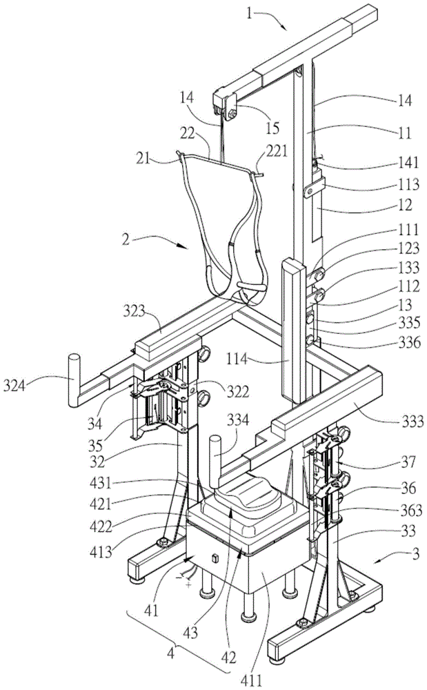
Fig. 1 is a perspective view of the present invention.
FIG. 2 is a perspective exploded view of a portion of the structure of the T-shaped hanger and the U-shaped base of the present invention.
Fig. 3 is a partially exploded perspective view of the left and right elevating outer sleeve seats and the adjusting belt seats of the present invention.
Fig. 4 is an exploded perspective view of the third adjustment seat in fig. 3.
Fig. 5 is a first embodiment of the left and right horizontal lifting tubes with underarm rods in fig. 3.
Fig. 6 is a second embodiment of the left and right horizontal lifting tubes with underarm rods in fig. 3.
Fig. 7 is a schematic perspective view showing an aspect of the present invention used for cervical traction adjustment.
Fig. 8 is a front and back view of the neck traction frame lifting adjustment of the present invention.
Fig. 9 is a second back view of the neck traction frame of the present invention for adjusting the elevation of the neck traction frame.
Fig. 10 is an exploded perspective view of the horizontal rotary drive platform structure of the present invention.
Fig. 11 is an exploded perspective view of the horizontal swivel stage structure of the present invention.
FIG. 12 is a perspective view of a hip pad of the first embodiment of the horizontal swivel platform of the present invention.
Fig. 13 is a posterior view of the invention in the ventro-thoracic region before vertebral adjustment.
Fig. 14 is a second posterior view of the invention after adjustment of the abdominocervical spine.
Fig. 15 is a rear view of the hip section rotational vibration in cooperation with the underarm lever embodiment of the present invention.
Fig. 16 is a partially enlarged view of a rhythm of a spinal condyle in fig. 15.
Fig. 17 is a partially enlarged view of the rhythm of the spinal condyle in fig. 15 a.
Fig. 18 is an exploded perspective view of a hip orthotic cushion according to a second embodiment of the horizontal swivel platform of the present invention.
Fig. 19 is a rear view of the hip segment rotational vibration of the present invention of fig. 13.
Fig. 20 is a partially enlarged view of the rhythm of the spinal condyle of fig. 19 a.
Fig. 21 is a second schematic view of the rhythm of the spinal condyle partially enlarged as shown in fig. 19B.
FIG. 22 is an exploded perspective view of a third embodiment of a hip orthotic pad according to the present invention.
FIG. 23 is a rear elevational view of a further embodiment of the hip section of the horizontal swivel platform of the present invention in rotational oscillation.
Fig. 24 is a schematic view of the rhythm of the spinal condyle partially enlarged at C in fig. 23.
Fig. 25 is a second schematic view of the rhythm of the spinal condyle partially enlarged in fig. 23C.
Detailed Description
Referring to fig. 1 to 6 and fig. 10 and 11, it can be seen that the present invention is an automatic or manual controller which can be set by a computer control program and performs the same use or individual adjustment of each part structure according to the best input data, which mainly comprises: t shape gallows 1, neck traction area 2, U shape base 3, horizontal gyration drive platform 4 constitute, wherein: the T-shaped hanger 1 is provided with a main lifting pipe 11, a first combining seat 111, a second combining seat 112 and a clamping seat 113 are correspondingly arranged at two side edges of the main lifting pipe 11, a soft cushion 114 is arranged at the other side edge, a first power telescopic actuator 12 (the first power telescopic actuator 12 can be suspended by weights with different equivalent weights to replace the first power telescopic actuator) and a second power telescopic actuator 13 are arranged at the other side edge of the main lifting pipe 11, wherein, a combining hole 121 at one end of the first power telescopic actuator 12 is arranged in the first combining seat 111 to be combined with a hole 1111 and is combined by a bolt 123 and a nut 124, the other end is combined with a buckling part 141 of a pulling belt 14 by a through hole 122 and is arranged in the clamping seat 113, the other end of the pulling belt 14 extends and pulls by a steering wheel set 15, a combining hole 131 at one end of the second power telescopic actuator 13 is correspondingly arranged in a third combining seat 311, the third connecting seat hole 3111 is connected with a bolt 133 and a nut 134, and the other end is inserted into the second connecting seat 112 through the shaft hole 132 and correspondingly connected with the hole through a bolt 1321 and a nut 1322; the neck traction belt 2 is extended from a traction rod 22 connected with the T-shaped hanger 1, the end parts 221 of the two ends of the traction rod 22 are provided with retaining rings 21 in an extending way, and the traction belt 2 penetrates through the retaining rings 21 to combine the two end parts 221 of the traction rod 22; the said shape base 3 is sleeved with a main lifting pipe 11 of the T-shaped hanger 1, the main lifting pipe 11 is sleeved in the pipe hole 312 of the main lifting pipe outer sleeve seat 31, the third combining seat 311 is arranged at the two sides of the main lifting pipe outer sleeve seat 31, the two sides of the U-shaped base 3 are respectively provided with a right lifting pipe outer sleeve seat 32 and a left lifting pipe outer sleeve seat 33, wherein, a right lifting pipe 322 with a plurality of holes 3221 is sleeved in the pipe hole 321 of the right lifting pipe outer sleeve seat 32, the pipe hole 341 of the first adjusting belt seat 34 and the pipe hole 351 of the second adjusting belt seat 35 are sleeved in sequence corresponding to the right lifting pipe 322, a right handle pad part 323 is extended at one end of the right lifting pipe 322 and is combined with a right handle 324 of a telescopic adjusting belt seat, a left lifting pipe 332 with a plurality of holes 3321 is also sleeved in sequence corresponding to the pipe hole of the left lifting pipe 332, the left lifting pipe 332 is sleeved with a third adjusting belt seat 36 in sequence, a left handle pad part 333 is extended from one end of the left lifting tube 332 and is combined with a telescopic adjustable left handle 334, a left and right handle combining part 335, 325 is extended from the corresponding combined end of the left and right handle pad parts 333, 323, the hole 115 of the main lifting tube 11 is locked and combined with the hole 115 of the main lifting tube 11 by at least one hole 3351, 3251 formed on the left and right handle combining part 335, 325, the holes 3351, 3251 of the left and right handle combining part 335, 325 are relative to the bolt 336 and the nut 337, the first adjusting belt seat 34, the second adjusting belt seat 35, the third adjusting belt seat 36, the structure same as the fourth adjusting belt seat 37 of the U-shaped base 3 are sleeved on the left and right lifting tubes 322, 332 in sequence, the first adjusting belt seat 34, the second adjusting belt seat 35, the third adjusting belt seat 36 and the fourth adjusting belt seat 37 are sleeved with the first adjusting belt 340 respectively, The second adjusting belt 350, the third adjusting belt 360 and the fourth adjusting belt 370 are assembled and exchanged from left to right, wherein only the third adjusting belt seat 36 is used as a representative, and the following detailed structure is exploded: the adjusting belt seat 36 is formed by pivotally installing rotating shafts 3621a, 3621b by two semicircular combinations on a fixed frame 362 and a movable frame 363, respectively, after the two ends of the rotating shafts 3621a, 3621b are additionally provided with ratchets 3622a, 3622b, and inserting pins 3623 at the two ends into through holes 36211a, 36211b to be fixed in large holes 36241 of upper and lower two plates 3624, and then passing through semicircular holes 36311a, 36311b at the other end of a wing plate 3631 to be combined, wherein, the upper and lower two plates 3624 of the fixed frame 362 are provided with guide grooves 3626 for elastically sliding, combining and reciprocating of a buckle 3625, the buckle 3625 is sleeved with an elastic component 3627, the upper and lower wing plates 3631 of the movable frame 363 are provided with guide grooves 3633 for elastically sliding, combining and reciprocating movement of the plate 3632, the elastic component 3634 is hooked by the plate 3632, a handle rod 3635 is sleeved between the wing plates 3631, the ends of the handle rod 35 are provided with concave parts 351a, 3638b and a fastening piece 3638C for combining with a fastening piece 3638, a connecting rod 3637 is further disposed in the middle of the wing plate 3631, fasteners 3638 are concavely disposed at two ends of the connecting rod 3637 to combine two upper and lower wing plates 3631, one end of a third adjusting belt 360 is disposed through the connecting rod 3637, and then clamped by two semicircular combined pivot shafts 3621a and 3621b, and passed through the handle rod 3635, and length and positioning and locking are controlled by the plate 3632, and a tube portion 3629 extends from a side surface of the fixing frame 362, so that the positioning rod 3628 is sequentially sleeved with an elastic component 36201, two fasteners 362811 and 362821, so that a fastening groove 362811 corresponding to a first neck portion 36281 of the positioning rod 3628 and a fastening groove 362821 corresponding to a second neck portion 36282, and then the positioning rod 3628 is integrally combined to the tube portion 3629 by a locking member 36283, and then a tube hole 361 of the third adjusting belt seat 36 is disposed on the right lifting tube 332, and the positioning rod 3628 corresponds to a hole 3321 of the right lifting tube 332 to achieve the effect of adjusting height; FIG. 5 is a first preferred embodiment of the present invention with an underarm rod 38, it is understood from the figure that the present invention can be provided with the underarm rod 38 with upper, lower, front and rear adjusting positions at the corresponding positions of the left lifting cross bar 3322 and the right lifting cross bar 3222 extending from the left and right lifting pipes 322, 332, a supporting portion 381 is provided above the underarm rod 38, which is an elastic covering structure at the front end of the supporting pipe 380 for supporting the underarm of the user, a sleeve hole 38210 provided on the pipe seat 3821 fixedly provided at the upper end 382 of the supporting rod is sleeved in the supporting pipe 380, a locking bolt 38211 provided at the side is used to fix the pipe seat 3821 and the supporting pipe 380, the lower end of the supporting rod 382 is sleeved in the corresponding hole 3830 of another adjusting seat 383, a locking bolt 3831 provided at the side of the adjusting seat 383 can adjust and fix the lifting of the supporting rod 382, an upper stop portion 3832 and a lower stop portion 3833 are provided at the front side of the adjusting seat 383, a concave part 384 is formed between the upper retaining part 3832 and the lower retaining part 3833, the concave part 384 is used to erect the armpit rod 38 at the corresponding position of the left lifting cross bar 3322 and the right lifting cross bar 3222 to match with different heights or uses of users, and the armpit rod 38 is sleeved according to needs, while fig. 6 is a second preferred embodiment of the armpit rod 38 of the present invention, as shown in the figure, the upper retaining part 3832, the lower retaining part 3833 and the concave part 384 formed therebetween of the armpit rod 38 of the present invention are reversely arranged to facilitate the use of users with different fat and thin statures or other requirements; referring to fig. 10 and 11 again, the horizontal rotation driving platform 4 is composed of a base 41, a horizontal rotation base 42, and a hip correction pad 43; the base 41 comprises a platform base 411, a shock-proof seat 412, a rotary motor gear installation platform 413, a vibrator 414, and a motor gear set 415, wherein the platform base 411 has a hole 4111, the hole 4111 is combined with a hole 4121 of the shock-proof seat 412 by a gasket 4112 and is rotationally locked by a bolt 4113 and a nut 4114, the top of the shock-proof seat 412 is sleeved with a plurality of elastic shock-proof pads 4122, the top surface of the shock-proof pads 4122 supports the rotary motor gear installation platform 413, the rotary motor gear installation platform has a plurality of protruding sleeved seat portions 4131 and a groove 4132, a vibrator 414 is fixedly arranged near the middle of the bottom of the rotary motor gear installation platform 413, in addition, a motor gear set 415 is additionally arranged near the middle of the upper surface of the rotary motor gear installation platform 413, the motor gear set 415 is correspondingly engaged with a driving gear 4151, the gear hole 41511 of the driving gear 51 is sleeved with two elastic gaskets 4152 and is tightly engaged with a bearing hole 41531 of the motor gear bearing 4153, the motor gear bearing 4153 is fixed in the groove 4132 of the rotary motor gear installation platform 413, and a horizontal rotary pedestal 42 is installed above the rotary motor gear installation platform 413, the horizontal rotary pedestal 42 is composed of a rotary pedestal upper cover 421 and a lower cover 422, the edge near the corner of the rotary pedestal upper cover 421 is installed with a plurality of eccentric rotary shaft members 4211 (i.e. bearing assemblies), the eccentric rotary shaft members 4211 are further composed of a fixed seat 42111, an upper end bearing 42112, an elastic bearing fixing sheet 42113, a first eccentric shaft arm 42114a, a second eccentric shaft arm 42114b and an elastic gasket 42115, the fixed seat 42111 is sequentially sleeved with the upper end bearing 42112 and an elastic bearing fixing sheet 42113 on the top surface, the elastic bearing fixing sheet 42113 is combined with a first eccentric shaft arm 42114a, and both sides of the first eccentric shaft arm 42114a are respectively provided with a long shaft 421141, a short shaft 421142, and a long shaft 421141 of the first eccentric shaft 421141a, the second eccentric shaft 421141a is combined with the second drive gear 4151, the second elastic washer 4152 and the motor gear bearing 4153 through the big hole 4221 of the lower cover 422 of the rotary table base and the second lower end bearing 4224, and then correspondingly combined through the gear hole 41511 and the bearing hole 41531; in addition, the second eccentric shaft arm 42114b, the third eccentric shaft arm 42114c and the fourth eccentric shaft arm 42114d are identical inert balance swing driven components, and only the second eccentric shaft arm 42114b is used for analysis, the second eccentric shaft arm 42114b has a supporting shaft 421143 and a short shaft 421144, so that after being sleeved with an elastic gasket 42115, the second eccentric shaft arm 42114b is combined with a lower end bearing 4224 and passes through a hole 4222 of the lower cover 422 of the rotary table seat to be combined with a lower end bearing 4223, the lower end bearing 4223 is sleeved on a sleeve seat 4131 of the rotary motor gear setting platform 413 to be correspondingly combined, and the top of the rotary table seat 42 is used for generating an inertial centrifugal force during the rotary motion to drive the plane to place a hip correction pad 43, and the hip correction pad 43 has a plurality of different rotary modes, please refer to fig. 12 to 17, only three representative modes are described as follows:
the first is that the upper surface of the arc seat cushion 431 is arc-shaped, and the lower surface is horizontal, so that the arc seat cushion can be stably placed on the rotary pedestal 42; the second is a balance disk 432, the upper and lower surface parts of which are arc; the third is a balance ball 433, the upper surface of which is horizontal and the lower surface of which is semicircular.
When the combined use, the T-shaped hanger 1 is connected with the traction rod 22 of the neck traction belt 2 by the buckle part 141 at one end of the traction belt 14, and is guided in by the steering wheel set 15 corresponding to the T-shaped hanger 1, so as to be combined with the main lifting pipe 11 at the other end and the through hole 122 of the power telescopic actuator 12, thereby achieving the traction effect of the head traction belt 2 by the telescopic action of the power telescopic actuator 12, and the horizontal rotary driving platform 4 is arranged at the corresponding position in the U-shaped base 3.
When using, please refer to fig. 7 to 9, it can be seen that the center of the human skeleton is indicated by the axis T and is used as the alignment line for positioning, when using the spinal melody exercise device to make the first power extension actuator 12 of the T-shaped hanger 1 generate the pulling force, the head of the neck traction belt 2 is lifted and lifted upwards by the pulling belt 14 connected with the pulling rod 22 of the neck traction belt 2, so as to increase the cervical joint clearance and align the line for positioning.
As shown in fig. 12 to 17, it can be seen that when the user supports the armpit against the left and right handle pads 333, 323 of the n-shaped base 3, the proper supporting height can be adjusted according to the height of the user, so as to lift the armpit upwards and raise the same, so as to raise the vertebral body of the user and reduce the stacking phenomenon, and the pelvis from the shoulder blade to the lumbar vertebra presents a state of no gravity pressure, so as to facilitate the return of the spine, and the n-shaped base 3 has a first adjusting strap seat 34, a second adjusting strap seat 35, a third adjusting strap seat 36 and a fourth adjusting strap seat 37, and the thoracic curvature disorder is slowly adjusted to the center position by the adjusting straps 340, 350, 360, 370 wound around the adjusting strap seats 34, 35, 36, 37, and cooperating with the left and right chest pressure applied to the front head A, B, C; the horizontal rotation driving platform 4 can make the pelvis do regular low-speed rotation swing for 10-60 times per minute, and horizontally rotate for 360 degrees leftwards or rightwards according to the direction of a drawing, so that the angle of the spine is reversely mechanically corrected and reset, when the pelvis of a user is seated on the hip correction pad 43, if the spinal part has only rotation symptoms, the arc seat pad 431 is adopted, and as shown in 16, the right side of the disease is rotated like PR (positive response) to generate reverse rotation direction adjustment; as shown in fig. 17, the rotation pedestal top cover 421 rotates in the right direction to cooperate with the arc seat 431 to generate a right torsion, and the reverse force channel rotation correction reset can make the disease rotate to the left, such as PL rotation adjustment, when the adjustment is performed, in addition, as shown in fig. 10, when the weight of the human body sits on the arc seat 431, the horizontal rotation pedestal 42, the horizontal rotation motor gear setting platform 413 and the vibrator 414 are stacked under the adjustment to generate a high speed of more than 1000 times per minute, so that the spinal joint can be loosened and activated, and the homing and guiding effects can be accelerated.
As shown in fig. 18 to 21, it can be seen from the drawings that the pelvis is rotated at a regular low speed 10-60 times per minute to horizontally rotate left or right to present S-rotation, so as to make the spine angle perform reverse mechanical restoration and reduction, the balance disc 432 is additionally adopted when the pelvis is seated on the hip correction pad 43 and the spine is bent, so that the part of the spinal cord of the spinal disorder is bent to the right and the rotation is reversely adjusted as shown by the PRI arrow, as shown in fig. 20, the upper cover 421 of the rotary table seat is rotated left to match with the balance disc 432 to generate the left torsion as shown by the PL I arrow of fig. 21, so as to generate the reverse force path to correct the reduction, so that the part of the spinal cord of the spinal disorder is bent to the left or adjusted by rotation, and the upper cover 421 of the rotary table seat is rotated right to match with the balance disc 432 to generate the right torsion, so as to correct the reduction, when the weight of the human body is seated on the balance disc 432, the horizontal rotary table, The horizontal rotary motor gear installation platform 413, the motor gear set 415 and the vibrating machine 414 generate high speed more than 1000 times per minute, so that the spinal joint can be loosened and activated, and the homing and correcting effects can be accelerated.
As shown in FIGS. 22 to 25, it can be seen that when the pelvis is rotated at a regular low speed 10-60 times per minute to horizontally rotate left or right to present S-rotation for the reverse mechanical correction and restoration of the vertebral angle, the pelvis is seated on the hip correction pad 43, and the symptom of pelvic malunion of the spine is caused by the pelvic balance ball 433, if the symptom is that part of the condyle is bent and rotated to the right and inclined to the arrow PRS as shown in FIG. 24, the upper cover 421 of the rotation pedestal will be twisted left by the left-rotation and the balance ball 433 will be twisted left to generate a reverse vector force, and the hip correction pad will be rotated to the left or right to generate a reverse force,
Automatic posture correction and resetting of angles; for the disease, as shown in fig. 25, part of the joint bends and rotates to the left and inclines in the arrow direction PLS, the upper lid 421 of the rotary table seat rotates to connect with the balance ball 433 to twist right, so as to generate the inverse force path and the automatic posture correction and restoration of the angle; when the user sits on the balance ball 433, the horizontal rotation pedestal 42, the horizontal rotation motor gear installation platform 413, the motor gear set 415 and the vibration machine 414 which are matched with each other at the lower part are promoted to rotate and/or vibrate at a high speed of more than 1000 times per minute, so that the spinal joint is loosened and activated, and the homing and guiding effects are accelerated.
In conclusion, the vertebra horizontal melody exercise device is applied to the horizontal melody exercise mode of physical therapy of cervical vertebra and backbone of vertebra of human body, so that the symptoms of aching pain and numbness of vertebra bodies, or lateral curvature of thoracic vertebra, lumbar rotation, curvature and pelvic inclination are gradually relieved, and clinical experiments prove that the rehabilitation device capable of recovering to a normal angle or position can be achieved; however, the above description is only for the purpose of illustrating the preferred embodiments of the present invention, and it is intended that the present invention cover modifications, alterations, changes, and equivalents of these embodiments as may be extended in the technical spirit and scope of the present invention.