Disclosure of Invention
The technical problem that this application was solved provides an annular suspended ceiling system, can effectively overcome the defect that exists among the prior art, can realize the rapid Assembly installation of furred ceiling part, can effectively improve on-the-spot installation effectiveness to and effectively reduce workman intensity of labour.
In order to solve the technical problem, the application provides an annular ceiling system, which comprises a plurality of corner ceiling modules and a plurality of straight ceiling modules; the corner ceiling modules are arranged at the corner positions of the annular ceiling system, the straight ceiling modules are arranged between two adjacent corner ceiling modules, and the corner ceiling modules and the straight ceiling modules are assembled and connected to form the annular ceiling system;
the straight ceiling module comprises a first ceiling horizontal plane and a first ceiling vertical plane, and the side edge of the first ceiling horizontal plane is connected with the bottom edge of the first ceiling vertical plane through an external corner keel to form an L-shaped structure of the straight ceiling module; the side edge of the horizontal plane of the first suspended ceiling, which is far away from the external corner keel, is set as a side wall of a connecting wall body, and the top edge of the vertical plane of the first suspended ceiling is set as a top wall of the connecting wall body;
the corner ceiling module comprises a second ceiling vertical surface and a second ceiling horizontal surface; the second ceiling vertical surface comprises a first vertical surface and a second vertical surface which are vertically arranged and are perpendicular to each other, and the first vertical surface and the second vertical surface form an internal corner of the ceiling module; the second ceiling horizontal plane comprises a rectangular plane, a first corner position of the rectangular plane is provided with a right-angle notch, and the first vertical surface and the second vertical surface are vertically connected to the right-angle notch; two side edges of the second ceiling horizontal plane, which are far away from the right-angle notch, are set as side walls of the connecting wall body, two side edges of the second ceiling horizontal plane, which are close to the right-angle notch, are set as first ceiling horizontal planes for connecting the straight ceiling modules, and the second ceiling horizontal plane is connected with the bottom edge of the second ceiling vertical plane through an external corner keel; and the top edge of the vertical surface of the second suspended ceiling is set as a top wall of the connecting wall body, and the side edge of the vertical surface of the first suspended ceiling is set as a vertical surface of the first suspended ceiling connected with the straight suspended ceiling module.
The annular ceiling system can also have the following characteristics,
the first ceiling horizontal plane comprises a first main keel and a first auxiliary keel, and the first main keel is arranged on the side edge of the first ceiling horizontal plane and is opposite to the external corner keel; the first auxiliary keel is arranged between the first main keel and the external corner keel, and two ends of the first auxiliary keel are respectively and vertically connected with the first main keel and the external corner keel; the first ceiling vertical surface comprises a second main keel and a second auxiliary keel, and the second main keel is arranged at the top edge of the first ceiling vertical surface and is opposite to the external corner keel; the second auxiliary keel is arranged between the second main keel and the external corner keel, and two ends of the second auxiliary keel are respectively and vertically connected with the second main keel and the external corner keel;
the second suspended ceiling horizontal plane comprises a third main keel, a fourth main keel, a third auxiliary keel and a fourth auxiliary keel; the third main keel and the fourth main keel are respectively arranged on two side edges of the horizontal plane of the second suspended ceiling far away from the right-angle notch; the third auxiliary keel and the fourth auxiliary keel are respectively arranged on two side edges of the horizontal plane of the second suspended ceiling close to the right-angle notch and are vertically connected to the external corner keel; the second suspended ceiling vertical surface comprises a fifth main keel, a sixth main keel, a fifth auxiliary keel and a sixth auxiliary keel; the fifth main keel is arranged on the top edge of the first vertical surface, and the fifth auxiliary keel is arranged between the fifth main keel and the external corner keel; the sixth main keel is arranged at the top edge of the second vertical surface, and the sixth auxiliary keel is arranged between the sixth main keel and the external corner keel;
the first main keel, the first auxiliary keel, the third main keel, the fourth main keel, the fifth main keel, the sixth main keel, the second auxiliary keel, the third auxiliary keel, the fourth auxiliary keel, the fifth auxiliary keel and the sixth auxiliary keel are all provided with U-shaped cavities.
The annular ceiling system can also have the following characteristics,
the first main keel and the first auxiliary keel, the second main keel and the second auxiliary keel, the third main keel and the third auxiliary keel, the fourth main keel and the fourth auxiliary keel, the fifth main keel and the fifth auxiliary keel and the sixth main keel and the sixth auxiliary keel are connected through a horizontal card inserting piece;
the third main keel and the fourth main keel are connected through a horizontal right-angle piece; the fifth main keel and the sixth main keel are connected through a vertical right-angle piece; between first false keel, external corner fossil fragments and the second false keel, between third false keel, external corner fossil fragments and the fifth false keel, between fourth false keel, external corner fossil fragments and the sixth false keel, all connect through ladder card plug-in components.
The annular ceiling system can also have the following characteristics,
the step card inserting piece comprises a step body, wherein the step body comprises a first transverse plate, a first vertical plate, a second transverse plate and a second vertical plate which are sequentially and vertically connected and combined to form a step shape; the first transverse plate is horizontally arranged at the top end of the ladder body, the first vertical plate is vertically arranged, the top edge of the first transverse plate is connected with the side edge of the first transverse plate, the second transverse plate is horizontally arranged, a group of opposite edges of the second transverse plate are respectively connected with the bottom edge of the first vertical plate and the top edge of the second vertical plate, and the second vertical plate is vertically arranged at the bottom end of the ladder body;
the first vertical plate and the second transverse plate are arranged to be connected with the external corner keel, the first transverse plate is arranged to be connected with a second auxiliary keel, a fifth auxiliary keel or a sixth auxiliary keel which is vertical to the external corner keel and is vertically arranged, and the second vertical plate is arranged to be connected with a first auxiliary keel, a third auxiliary keel or a fourth auxiliary keel which is vertical to the external corner keel and is horizontally arranged;
the external corner keel is provided with an L-shaped cavity, a transverse plate and a vertical plate are respectively arranged on two sides of a cavity opening of the L-shaped cavity, and folded edges bent inwards are respectively arranged at the tail ends of the transverse plate and the vertical plate; the first group of opposite sides of the first transverse plate are provided with first clamping and inserting plates which extend upwards and are vertical to the first transverse plate, and the first group of opposite sides of the first transverse plate are vertical to the side edge of the first transverse plate connected with the first vertical plate; two sides of the first vertical plate are provided with first clamping and hanging plates which extend towards the inner side of the ladder and are vertical to the first vertical plate;
two sides of the second vertical plate are provided with second card inserting plates which extend towards the outer side of the ladder and are vertical to the second vertical plate; the first group of opposite sides of the second transverse plate are provided with second clamping and hanging plates which extend downwards and are vertical to the second transverse plate, and the first group of opposite sides of the second transverse plate are vertical to the side edge of the second transverse plate connected with the second vertical plate; two side edges of the U-shaped cavity are connected with the first card inserting plate and the second card inserting plate in a clinging manner, and the folded edges bent inwards of the U-shaped cavity are arranged to clamp the first card inserting plate and the second card inserting plate; hook-shaped structures are symmetrically arranged on two sides of the first clamping and hanging plate and two sides of the second clamping and hanging plate, and the hook-shaped structures are arranged to hook the inward bent folded edge of the L-shaped cavity.
The annular ceiling system can also have the following characteristics,
the horizontal card plug-in piece comprises a first transverse plug board and a first vertical plug board which are perpendicular to each other, the side edge of the first transverse plug board is connected with the top edge of the first vertical plug board, the first transverse plug board is arranged to be connected with the main keel, and the first vertical plug board is arranged to be connected with the auxiliary keel;
the first group of opposite sides of the first transverse inserting plate are provided with third vertical plates which extend downwards and are vertical to the first transverse inserting plate, the first group of opposite sides of the first transverse inserting plate are vertical to the side edges of the first transverse inserting plate connected with the first vertical inserting plate, and hook-shaped structures are symmetrically arranged on two sides of each third vertical plate; the first group of opposite sides of the first vertical inserting plate are provided with fourth vertical plates which extend outwards and are vertical to the first vertical inserting plate, and the first group of opposite sides of the first vertical inserting plate are vertical to the side edges of the first vertical inserting plate connected with the first transverse inserting plate;
the first transverse inserting plate is arranged to hook an inward bent folded edge of the U-shaped cavity through the hook-shaped structure of the third vertical plate; the first vertical inserting plate is vertically inserted into the U-shaped cavity, and the symmetrically arranged fourth vertical plates are respectively tightly attached to two sides of the U-shaped cavity.
The annular ceiling system can also have the following characteristics,
the horizontal right-angle part comprises a rectangular body, and a third transverse inserting plate and a fourth transverse inserting plate which are mutually flush are respectively arranged on the adjacent side edges of the rectangular body; the third transverse inserting plate and the fourth transverse inserting plate are arranged in parallel on the rectangular body; the first group of opposite sides of the third transverse inserting plate are both provided with seventh vertical plates extending upwards, and the first group of opposite sides of the third transverse inserting plate are perpendicular to the side edges of the third transverse inserting plate connected with the rectangular body; the first group of opposite sides of the fourth transverse inserting plate are both provided with eighth vertical plates extending upwards, and the first group of opposite sides of the fourth transverse inserting plate are perpendicular to the side edges of the fourth transverse inserting plate connected with the rectangular body;
the third transverse inserting plate and the fourth transverse inserting plate are respectively inserted into a third main keel and a fourth main keel which are vertically connected with each other; the third transverse inserting plate and the fourth transverse inserting plate are arranged to be in close fit connection with the bottom edge of the U-shaped cavity, and the seventh vertical plate and the eighth vertical plate are arranged to be in close fit with the side edge of the U-shaped cavity; two side edges of the U-shaped cavity are respectively provided with an inward bent hem which is used for clamping the seventh vertical plate and the eighth vertical plate; two side edges of the U-shaped cavity are perpendicular to the bottom edge, and the side edges are arranged to clamp the third transverse inserting plate and the fourth transverse inserting plate; the lower surfaces of the third transverse inserting plate and the fourth transverse inserting plate are flush with the upper surface of the rectangular body, and the thickness of the plate of the rectangular body is equal to that of the keel.
The annular ceiling system can also have the following characteristics,
the vertical right-angle piece comprises an L-shaped body, and the L-shaped body comprises a third vertical inserting plate and a fourth vertical inserting plate which are connected through respective side edges and are perpendicular to each other; the top edge and the bottom edge of the third vertical inserting plate are provided with third transverse plates, and the third transverse plates extend outwards and are far away from the fourth vertical inserting plate; the top edge and the bottom edge of the fourth vertical inserting plate are provided with fourth transverse plates, and the fourth transverse plates extend outwards and are far away from the third vertical inserting plate;
the third vertical inserting plate and the fourth vertical inserting plate which are vertical to each other are arranged to be respectively inserted into a fifth main keel and a sixth main keel which are vertically connected with each other; the third vertical inserting plate and the fourth vertical inserting plate are arranged to be tightly attached to the bottom edge of the U-shaped cavity, and the third transverse plate and the fourth transverse plate are arranged to be tightly attached to the side edge of the U-shaped cavity; two side edges of the U-shaped cavity are respectively provided with a folded edge which is bent inwards, and the folded edges are arranged to clamp the third transverse plate and the fourth transverse plate; two sides of the U-shaped cavity are perpendicular to the bottom side of the U-shaped cavity respectively, and the sides are arranged to clamp the third vertical inserting plate and the fourth vertical inserting plate.
The annular ceiling system can also have the following characteristics,
the side edges of the first suspended ceiling horizontal plane, the second suspended ceiling horizontal plane and the wall body are connected, the top edges of the first suspended ceiling vertical surface, the second suspended ceiling vertical surface and the wall body are all provided with hanging keels, and the corresponding positions of the wall body are provided with wall-following bearing keels which are connected with the hanging keels in a matched mode.
The annular ceiling system can also have the following characteristics,
the hanging keel comprises a fifth vertical plate, a lapping plate and a hanging plate, the lapping plate and the hanging plate are respectively arranged on two sides of the fifth vertical plate, the lapping plate is connected with the bottom end of the fifth vertical plate, and the lapping plate and the fifth vertical plate are arranged to be connected with the edge of a suspended ceiling module; the hanging plate is connected with the middle part of the fifth vertical plate and is provided with a hanging bearing keel along the wall;
a cavity between the hanging plate and the fifth vertical plate is set as a hanging cavity; the tail end of the hanging plate is a free end, the tail end is inclined inwards, and the middle part of the hanging plate is a bent part; the area between the bending part and the tail end of the hanging plate is provided with a hanging plate for tightly clamping the bearing keel along the wall; the bending part of the hanging plate and the hanging plate along the wall bearing keel are provided with the same bending structure; the bottom of fifth riser with the contained angle between the lapping plate sets up to 90.
The annular ceiling system can also have the following characteristics,
the wall-following bearing keel comprises a wall connecting plate, a bottom plate and a hanging plate, wherein the bottom end of the hanging plate is connected with the bottom ends of the wall connecting plate respectively, the wall connecting plate is arranged to be connected with a wall, and the hanging plate is arranged to be a hanging keel;
the top end of the hanging plate is set to be a free end, and the top end inclines outwards; an included angle between the bottom end of the hanging plate and the bottom plate is set to be a, and a is smaller than 90 degrees; the middle part of the hanging plate is provided with a bent part; the area between the bending part and the top end of the hanging plate is set as an insertion guide area of the hanging keel to be hung; the area between the bending part and the bottom end of the hanging plate is set as a hanging clamping area of the hanging keel to be hung; the bending part of the hanging plate and the hanging plate to be hung with the hanging keel are provided with the same bending structure; the included angle between the bottom end of the wall connecting plate and the bottom plate is set to be 90 degrees.
The above technical scheme of this application has following beneficial effect:
according to the invention, through optimizing the arranged components, the defects in the prior art can be effectively overcome, the rapid assembly and installation of the ceiling module can be realized, the field installation efficiency can be effectively improved, and the labor intensity of workers can be effectively reduced.
Additional features and advantages of the application will be set forth in the description which follows, and in part will be obvious from the description, or may be learned by the practice of the embodiments of the invention. The objectives and other advantages of the application may be realized and attained by the structure particularly pointed out in the written description and claims hereof as well as the appended drawings.
Detailed Description
Hereinafter, embodiments of the present application will be described in detail with reference to the accompanying drawings. It should be noted that the embodiments and features of the embodiments in the present application may be arbitrarily combined with each other without conflict.
Referring to figures 1, 2 and 3,
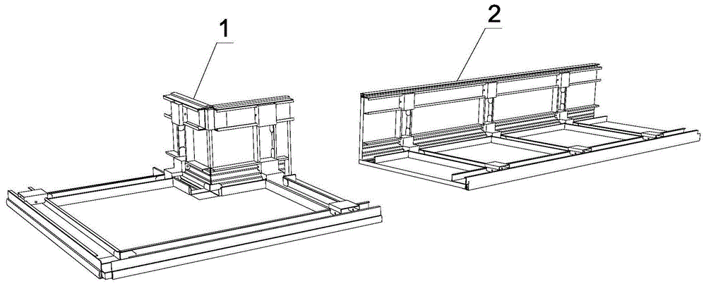
the invention provides an annular ceiling system which comprises a plurality of corner ceiling modules 1 and a plurality of straight ceiling modules 2; corner furred ceiling module 1 is established in annular furred ceiling system's turning position, and straight type furred ceiling module 2 is established between two adjacent corner furred ceiling modules, and corner furred ceiling module 1 is used for constituting annular furred ceiling system with straight type furred ceiling module 2 assembled connection. In the specific operation, the annular ceiling system adopts the modular design, the rapid assembly and installation of the ceiling part can be realized, the field installation efficiency can be effectively improved, and the labor intensity of workers can be effectively reduced.
As shown in fig. 4, the straight ceiling module may include a first ceiling horizontal surface 10 and a first ceiling vertical surface 11, wherein the side edges of the first ceiling horizontal surface 10 are connected with the bottom edges of the first ceiling vertical surface 11 through external corner keels 12, and form an L-shaped structure of the straight ceiling module; the side edge of the first ceiling horizontal surface 10, which is far away from the external corner keel 12, is set as a connecting wall side wall, and the top edge of the first ceiling vertical surface 11 is set as a connecting wall top wall; in the concrete operation, can assemble above-mentioned straight type furred ceiling module, and then be connected through its accessory between and the wall body, can realize holistic quick installation operation. In addition, the back surface of the keel is provided with the plate, so that the plate can be correspondingly fixed, and a ceiling decorative surface is formed
Further, the first ceiling horizontal plane 10 comprises a first main keel 13 and a first auxiliary keel 14, wherein the first main keel 13 is arranged on the side edge of the first ceiling horizontal plane 10 and is opposite to the external corner keel 12; the first auxiliary keel 14 is arranged between the first main keel 13 and the external corner keel 12, and two ends of the first auxiliary keel are respectively and vertically connected with the first main keel 13 and the external corner keel 12; the first suspended ceiling vertical surface 11 comprises a second main keel 15 and a second auxiliary keel 16, wherein the second main keel 15 is arranged at the top edge of the first suspended ceiling vertical surface 11 and is opposite to the external corner keel 12; the second vice fossil fragments 16 set up between second main joist 15 and external corner fossil fragments 12, and both ends are perpendicular connection second main joist 15 and external corner fossil fragments 12 respectively.
In the specific operation, the first main keel 13, the first auxiliary keel 14, the second main keel 15 and the second auxiliary keel 16 are all provided with U-shaped cavities, for example, covering keels commonly used in the market can be adopted; in addition, the first main keel 13 and the first auxiliary keel 14, and the second main keel 15 and the second auxiliary keel 16 are connected through horizontal clamping inserts 200; the first cross runner 14, male corner runner 12 and second cross runner 16 are connected by a step clip insert 400.
As shown in fig. 5 and 6, the corner ceiling module may include a second ceiling vertical surface and a second ceiling horizontal surface 50; the second ceiling vertical surface comprises a first vertical surface 52 and a second vertical surface 51 which are vertically arranged and are perpendicular to each other, and the first vertical surface 52 and the second vertical surface 51 form an internal corner of the ceiling module; the second ceiling horizontal plane 50 comprises a rectangular plane, a first corner of the rectangular plane is provided with a right-angle notch, and the first vertical surface 52 and the second vertical surface 51 are vertically connected to the right-angle notch; two side edges of the second ceiling horizontal plane 50, which are far away from the right-angle gap, are set as connecting wall side walls, two side edges close to the right-angle gap are set as first ceiling horizontal planes for connecting the straight ceiling modules, and the second ceiling horizontal plane 20 is connected with the bottom edge of the second ceiling vertical surface through the external corner keel 12; the top edge of the vertical surface of the second suspended ceiling is set as a top wall of the connecting wall body, and the side edge of the vertical surface of the first suspended ceiling is set as a vertical surface of the first suspended ceiling connected with the straight suspended ceiling module. In the concrete operation, can assemble above-mentioned corner furred ceiling module, and then be connected through its accessory between and the wall body, can realize holistic quick installation operation. Fig. 5 is a block diagram of a ceiling module with a sheet, and fig. 6 is a block diagram of a framework of the ceiling module. Through the back installation panel at fossil fragments, can realize the corresponding fixed of panel, and then form the furred ceiling decorative cover.
Preferably, in the practice of the present invention, ceiling level 50 includes a third main runner 53, a fourth main runner 54, a third cross runner 55, and a fourth cross runner 56; the third main keel 53 and the fourth main keel 54 are respectively arranged on two side edges of the ceiling horizontal plane 50 far away from the right-angle notch; the third cross keel 55 and the fourth cross keel 56 are respectively arranged on two side edges of the ceiling horizontal plane 50 close to the right-angle notch and are vertically connected to the external corner keel 12; the vertical surface of the suspended ceiling comprises a fifth main keel 57, a sixth main keel 58, a fifth auxiliary keel 59 and a sixth auxiliary keel 60; the fifth main runner 57 is arranged on the top side of the first vertical surface 52, and the fifth cross runner 59 is arranged between the fifth main runner 57 and the external corner runner 12; a sixth main runner 58 is provided at the top edge of the second riser 51, and a sixth cross runner 60 is provided between the sixth main runner 58 and the male corner runner 12; the third main keel 53, the fourth main keel 54, the fifth main keel 57, the sixth main keel 58, the third cross keel 55, the fourth cross keel 56, the fifth cross keel 59 and the sixth cross keel 60 are all provided with U-shaped cavities.
In the specific operation, the third main keel 53 is connected with the fourth main keel 54 through a water straight angle piece 300, and the fifth main keel 57 is connected with the sixth main keel 58 through a vertical angle piece 100; the third main keel 53 and the third auxiliary keel 55, the fourth main keel 54 and the fourth auxiliary keel 56, the fifth main keel 57 and the fifth auxiliary keel 59, and the sixth main keel 58 and the sixth auxiliary keel 60 are connected through horizontal clamping inserts 200; the third cross runner 55, the male angle runner 12 and the fifth cross runner 59, and the fourth cross runner 56, the male angle runner 12 and the sixth cross runner 60 are connected by a step clip 400.
The composition and connection relationship of each component (step card plug-in, horizontal right angle piece, vertical right angle piece, etc.) will be explained in detail below in combination with the corner ceiling module, and the component connection relationship of the straight type ceiling module refers to the corner ceiling module, and is not repeated here.
As shown in fig. 7 and 8, the ladder card connector has the following structure:
the ladder card insert 400 may include a ladder body including a first transverse plate 401, a first vertical plate 402, a second transverse plate 403 and a second vertical plate 404, which are vertically connected in sequence and combined to form a ladder shape; the horizontal setting of first diaphragm 401 is on the top of ladder body, and the side of first diaphragm 401 is connected to the vertical setting and the topside of first riser 402, and the setting of second diaphragm 403 level and a set of opposite side connect the base of first riser 402 and the topside of second riser 404 respectively, and the vertical setting of second riser 404 is in the bottom of ladder body. In operation, the male corner keel 12 and the corresponding cross keel may be operatively connected by the ladder clip insert 400 described above.
Preferably, the first vertical plate 402 and the second horizontal plate 403 are arranged to connect the external corner keel 12, the first horizontal plate 401 is arranged to connect the fifth cross keel 59 or the sixth cross keel 60 which is perpendicular to the external corner keel 12 and vertically arranged, and the second vertical plate 404 is arranged to connect the third cross keel 55 or the fourth cross keel 56 which is perpendicular to the external corner keel 12 and horizontally arranged. Furthermore, the external corner keel 12 has an L-shaped cavity, a horizontal plate and a vertical plate are respectively arranged on two sides of the cavity opening of the L-shaped cavity, and the ends of the horizontal plate and the vertical plate are both provided with folded edges bent inwards. Correspondingly, the first keel and the second keel are provided with U-shaped cavities, and two sides of the opening of each U-shaped cavity are respectively provided with a folded edge which is bent inwards.
In order to optimize the connecting structure between the ladder card plug-in unit and the keel; the first group of opposite sides of the first transverse plate 401 in this application are provided with a first card inserting plate 405 extending upwards and perpendicular to the first transverse plate 401, and the first group of opposite sides of the first transverse plate 401 are perpendicular to the side where the first transverse plate 401 is connected with the first vertical plate 402. In the specific operation, the first card inserting plate 405 is inserted into the cavity of the keel along the end part of the keel, so that the connection and fixation between the keel and the step card inserting piece can be realized.
In the present application, first hanging plates 406 extending inward of the steps and perpendicular to the first riser 402 are provided on both sides of the first riser 402. In the specific operation, the upper edge of the L-shaped cavity of the external corner keel 12 is hooked by the first hooking plate 406, so that the connection and fixation between the upper edge of the external corner keel 12 and the step card insertion member can be realized.
In the present application, second snap plates 408 extending outward from the steps and perpendicular to the second riser 404 are provided on both sides of the second riser 404. In the specific operation, the second card inserting plate 408 is inserted into the cavity of the keel along the end of the keel, so that the connection and fixation between the keel and the step card inserting member can be realized.
The first group of opposite sides of the second transverse plate 403 in this application are provided with the second clamping and hanging plate 407 which extends downwards and is perpendicular to the second transverse plate 403, the first group of opposite sides of the second transverse plate 403, and the sides which are perpendicular to the second transverse plate 403 and the second vertical plate 404 are connected. In the specific operation, the lower edge of the L-shaped cavity of the external corner keel 12 is hung through the second hanging clamping plate 407, so that the connection and fixation between the lower edge of the external corner keel 12 and the step clamping plug-in unit can be realized.
Preferably, two side edges of the U-shaped cavity are tightly attached to connect the first card insertion plate 405 and the second card insertion plate 408, and the inward bent folded edge of the U-shaped cavity is configured to tightly clamp the first card insertion plate 405 and the second card insertion plate 408; the folded edge can effectively ensure that the corresponding connecting part of the ladder card plug-in cannot slide out of the U-shaped cavity in the installation process.
Preferably, hook-shaped structures are symmetrically arranged on both sides of the first clamping and hanging plate 406 and both sides of the second clamping and hanging plate 407, and the hook-shaped structures are configured to hook the inward bent folded edge of the L-shaped cavity; the hook-shaped structure can effectively improve the actual installation efficiency.
Preferably, both sides of the first hanging plate 406 and both sides of the second hanging plate 407 are provided with a connecting hole. The connecting holes can be used for improving the relative stability of the oppositely arranged first clamping and hanging plate 406 and the oppositely arranged second clamping and hanging plate 407 by penetrating through the metal rod piece.
As shown in fig. 9 and 10, the horizontal card insert has the following structure:
the horizontal card plug-in unit 200 may include a first horizontal plug-in board 201 and a first vertical plug-in board 202 which are perpendicular to each other, wherein a side edge of the first horizontal plug-in board 201 is connected with a top edge of the first vertical plug-in board 202, the first horizontal plug-in board 201 is configured to be connected with a main keel, and the first vertical plug-in board 202 is configured to be connected with a secondary keel; the first group of opposite sides of the first transverse inserting plate 201 are provided with third vertical plates 203 which extend downwards and are perpendicular to the first transverse inserting plate 201, the first group of opposite sides of the first transverse inserting plate 201 are perpendicular to the side edges of the first transverse inserting plate 201 connected with the first vertical inserting plate 202, and hook-shaped structures are symmetrically arranged on two sides of each third vertical plate 203; the first group of opposite sides of the first vertical insertion plate 202 are provided with a fourth vertical plate 204 extending outwards and perpendicular to the first vertical insertion plate 202, and the first group of opposite sides of the first vertical insertion plate 202 are perpendicular to the side of the first vertical insertion plate 202 connected with the first transverse insertion plate 201.
Further, the first transverse insertion plate 201 and the first vertical insertion plate 202, which are perpendicular to each other, are arranged to be connected to the keels, which are perpendicular to each other, respectively. In the specific operation, the two keels which are horizontally arranged and mutually perpendicular to each other can be effectively connected through the horizontal clamping plug-in unit 200, wherein the cavity openings of the keels are arranged upwards, and the end parts of the keels are vertically connected to the middle position of the other keel; the first transverse inserting plate 201 and the correspondingly arranged third vertical plate 203 are connected with the keel on one side, and the first vertical inserting plate 202 and the correspondingly arranged fourth vertical plate 204 are connected with the keel on the other side, so that the fixed connection between the keels can be realized.
Preferably, this application above-mentioned fossil fragments have the U die cavity body, and two sides of U die cavity are provided with the hem of inside buckling respectively. In the specific operation of the application, the included angle between the folded edge of the U-shaped cavity and the side edge is set to be a right angle; or the included angle between the folded edge of the U-shaped cavity and the side edge is set to be an acute angle; through the included angle setting of above-mentioned right angle or acute angle, can effectively avoid third riser 203 and fourth riser 204 roll-off U type cavity in the installation.
Further, the first horizontal inserting plate 201 is provided with a hook-shaped structure through the third vertical plate 203, and an inward bent folded edge of the U-shaped cavity is hooked; the first vertical inserting plate 202 is arranged to be vertically inserted into the U-shaped cavity, and the symmetrically arranged fourth vertical plates 204 are arranged to be respectively tightly attached to two sides of the U-shaped cavity.
In the specific operation, the hook-shaped structure of the third vertical plate 203 is used for hooking the folded edge position of the keel, so that the keel can be connected with one side of the horizontal card plug-in unit; furthermore, the fourth vertical plate 204 of the first vertical insertion plate 202 is clamped in two side edges of the U-shaped cavity, so that the keel can be connected with the other side of the horizontal insertion plate. Further, the third riser 203 of this application still is provided with the connecting hole. The connecting holes can be used for improving the relative stability of the oppositely arranged third vertical plate 203 by penetrating through the metal rod.
Referring to fig. 11 and 12, the structure of the water flat corner fitting is as follows:
the horizontal right-angle component 300 can comprise a rectangular body 301, wherein the adjacent side edges of the rectangular body 301 are respectively provided with a third transverse inserting plate 302 and a fourth transverse inserting plate 303 which are mutually flush, and the third transverse inserting plate 302 and the fourth transverse inserting plate 303 are both arranged in parallel on the rectangular body 301; the first group of opposite sides of the third transverse inserting plate 302 are provided with seventh vertical plates 304 extending upwards, and the first group of opposite sides of the third transverse inserting plate 302 are perpendicular to the side edges of the third transverse inserting plate 302 connected with the rectangular body 301; the first group of opposite sides of the fourth transverse inserting plate 303 are provided with eighth vertical plates 305 extending upwards, and the first group of opposite sides of the fourth transverse inserting plate 303 are perpendicular to the side edges of the fourth transverse inserting plate 303 connected with the rectangular body 301.
Further, the third and fourth horizontal insertion plates 302 and 303 may be configured to be inserted into the third and fourth main runners 53 and 54, respectively, which are vertically connected to each other. In a specific operation, the two keels which are horizontally arranged and mutually perpendicular to each other can be effectively connected through the horizontal right-angle member 300, wherein the cavities of the keels are arranged upwards, and the end part of one keel is vertically contacted with the end part of the other keel; the third horizontal inserting plate 302 and the correspondingly arranged seventh vertical plate 304 are connected with the keel on one side, and the fourth horizontal inserting plate 303 and the correspondingly arranged eighth vertical plate 305 are connected with the keel on the other side, so that the keels are fixedly connected.
Preferably, the keel has a U-shaped cavity, the third and fourth lateral insert plates 302 and 303 are disposed to be closely attached to the bottom edge of the U-shaped cavity, and the seventh and eighth vertical plates 304 and 305 are disposed to be closely attached to the side edge of the U-shaped cavity. Furthermore, two sides of the above-mentioned U type cavity of this application are provided with the hem of inside buckling respectively, and the hem sets up to chucking seventh riser 304 and eighth riser 305. In the concrete operation, through the above-mentioned hem of inwards buckling, can be with seventh riser 304 and eighth riser 305 chucking to restrict its roll-off U die cavity body, can effectively improve the stability of connecting
Preferably, to further enable gripping of the seventh riser 304 and the eighth riser 305; in the specific operation of this application, the hem of U type cavity sets up to right angle or acute angle with the contained angle of side. Through the included angle setting of above-mentioned right angle or acute angle, can effectively avoid seventh riser 304 and eighth riser 305 roll-off U type cavity in the installation. In a specific operation, two side edges of the U-shaped cavity are perpendicular to the bottom edge, and the side edges are configured to clamp the third transverse inserting plate 302 and the fourth transverse inserting plate 303. The third transverse inserting plate 302 and the fourth transverse inserting plate 303 are effectively clamped through the side edges of the U-shaped cavity, the seventh vertical plate 304 and the eighth vertical plate 305 are effectively clamped through the folded edges of the U-shaped cavity, and finally, the integral clamping and fixing operation can be realized. The seventh vertical plate 304 and the eighth vertical plate 305 are respectively and vertically connected with the upper surfaces of the third transverse insertion plate 302 and the fourth transverse insertion plate 303.
Preferably, the lower surfaces of the third and fourth transverse insertion plates 302, 303 are flush with the upper surface of the rectangular body 301, and the plate thickness of the rectangular body 301 is equal to that of the keel. In a specific operation, the lower surfaces of the third transverse inserting plate 302 and the fourth transverse inserting plate 303 are flush with the upper surface of the rectangular body 301, so as to connect the rectangular body 301 with the end surface of a keel, and the third transverse inserting plate 302 and the fourth transverse inserting plate 303 are inserted into a U-shaped cavity of the keel, one side of the rectangular body 301 is connected with the keel on one side, and the adjacent side of the rectangular body 301 is connected with the other keel. Wherein, rectangle body 301 chucking is in the tip of fossil fragments, and the third is violently inserted plate 302 and the horizontal picture peg 303 of fourth are installed in the U die cavity internally, can effectively improve connection stability. It should be noted that, as shown in fig. 1 and fig. 2, the mutually perpendicular external corner keels 12 can also be effectively connected through the above-mentioned horizontal right-angle member 300, specifically, the connection can be realized by inserting into the L-shaped cavity and clamping at the inward-bent hem position of the L-shaped cavity; for a specific connection structure, please refer to the connection between the main keels above, which is not described herein again.
As shown in fig. 13 and 14, the vertical right-angle component has the following structure:
the vertical right-angle part 100 may include an L-shaped body, and the L-shaped body includes a third vertical insertion plate 101 and a fourth vertical insertion plate 102 which are connected through respective side edges and are perpendicular to each other; the top edge and the bottom edge of the third vertical inserting plate 101 are both provided with a third transverse plate 103, and the third transverse plate 103 extends outwards and is far away from the fourth vertical inserting plate 102; the top edge and the bottom edge of the fourth vertical insertion plate 102 are provided with a fourth horizontal plate 104, and the fourth horizontal plate 104 extends outwards and is far away from the third vertical insertion plate 101. Further, the third vertical insertion plate 101 and the fourth vertical insertion plate 102, which are perpendicular to each other, may be configured to be inserted into the fifth main keel 57 and the sixth main keel 58, which are perpendicular to each other.
In a specific operation, the fifth main keel 57 and the sixth main keel 58 which are horizontally arranged and mutually perpendicular can be effectively connected through the vertical right-angle piece, wherein the cavity openings of the keels point to one side instead of being arranged upwards; the third vertical insertion plate 101 and the correspondingly arranged third transverse plate 103 are connected with the keel on one side, and the fourth vertical insertion plate 102 and the correspondingly arranged fourth transverse plate 104 are connected with the keel on the other side, so that the keels are fixedly connected.
Preferably, the keel has a U-shaped cavity, the third vertical insertion plate 101 and the fourth vertical insertion plate 102 are disposed to be closely attached to the bottom side of the U-shaped cavity of the keel, and the third horizontal plate 103 and the fourth horizontal plate 104 are disposed to be closely attached to the side of the U-shaped cavity. Further, two sides of the above-mentioned U type cavity of this application are provided with the hem of inside buckling respectively, and the hem sets up to chucking third diaphragm 103 and fourth diaphragm 104. In the concrete operation, through the above-mentioned hem of inwards buckling, can be with third diaphragm 103 and fourth diaphragm 104 chucking to restrict its roll-off U die cavity body, can effectively improve the stability of connecting.
Preferably, in order to further clamp the third transverse plate 103 and the fourth transverse plate 104; in the specific operation of the application, the included angle between the folded edge of the U-shaped cavity and the side edge is set to be a right angle; or the included angle between the folded edge of the U-shaped cavity and the side edge is set to be an acute angle; through the included angle setting of above-mentioned right angle or acute angle, can effectively avoid third diaphragm 103 and fourth diaphragm 104 roll off U type cavity in the installation. In specific operation, two side edges of the U-shaped cavity body can be perpendicular to the bottom edge of the U-shaped cavity body respectively, and the side edges are configured to clamp the third vertical insertion plate 101 and the fourth vertical insertion plate 102. The third vertical inserting plate 101 and the fourth vertical inserting plate 102 are effectively clamped through the side edge of the U-shaped cavity, the third transverse plate 103 and the fourth transverse plate 104 are effectively clamped through the folded edge of the U-shaped cavity, and finally, the whole clamping and fixing operation can be achieved.
As shown in fig. 15, 16, 17, 18 and 19,
in order to effectively improve the quick connection between the ceiling module and the wall body; preferably, in the specific operation of the invention, the side edges of the first ceiling horizontal plane and the second ceiling horizontal plane connected with the wall body, and the top edges of the first ceiling vertical plane and the second ceiling vertical plane connected with the wall body are all provided with the hanging keels 17, and the corresponding positions of the wall body are provided with the wall-following bearing keels 18 in matching connection with the hanging keels.
As shown in fig. 20 and 21, the mounting keel 17 has the following structure:
the hanging keel 17 can comprise a fifth vertical plate 31, a lapping plate 32 and a hanging plate 33, the lapping plate 32 and the hanging plate 33 are respectively arranged at two sides of the fifth vertical plate 31, the lapping plate 32 is connected with the bottom end of the fifth vertical plate 31, and the lapping plate 32 and the fifth vertical plate 31 are arranged to be connected with the edge of a ceiling module to be installed; the hanging plate 33 is connected with the middle part of the fifth vertical plate 31, and the hanging plate 33 is arranged to be hung on the wall bearing keel 18.
In the specific operation, the wall bearing keels 18 can be connected and fixed on the wall in advance, and then the hanging plates of the hanging keels 17 can be hung on the corresponding parts of the wall bearing keels 18, so that the connection of the hanging keels 17 can be realized; wherein the bridging plate 32 of the mounting keel 17 is arranged to support and connect the suspended ceiling system. The installation operation of the whole ceiling system can be realized through the hanging operation between the hanging keel 17 and the wall bearing keel 18.
Preferably, in order to improve the hanging stability of the hanging keel 17; the cavity between the hanging plate 33 and the fifth vertical plate 31 is provided with a hanging cavity 35. In the specific operation, the hanging cavity 35 can be connected with the corresponding hanging part of the bearing keel 18 along the wall in a clamping manner, so that the hanging operation can be realized.
Preferably, in order to optimize the integral connection structure of the mounting keel 17; the tail end of the hanging plate 33 is arranged to be a free end, the tail end is inclined inwards, and the middle of the hanging plate 33 is arranged to be a bending part 34. Wherein, the region between the kink 34 of link plate 33 and the bottom sets up to the chucking and bears the hitch plate of fossil fragments 18 along the wall. In operation, the inwardly inclined bottom edge forms a closing-in of the hanging cavity 35; the inwardly inclined bottom edge may be hooked to a corresponding portion of the load bearing wall runner 18 and the entire hang plate 33 may be inserted into the opposing part of the load bearing wall runner 18.
Further, the bent portion 34 of the hanging plate 33 is provided with the same bent structure as the hanging plate along the wall bearing keel 18. In the concrete operation, the same bending structure can realize the maximum area fitting of the board surface in the connection matching process, and can realize the most stable hanging connection mode.
Preferably, in order to improve the connection stability of the mounting keel 17; the contained angle between the bottom of the above-mentioned fifth riser 31 of this application and the overlap joint board 32 sets up to 90, and the overlap joint board 32 sets up the shaping of bending as an organic whole with fifth riser 31, and link plate 33 sets up to welded connection structure with fifth riser 31. In the specific operation, the vertical arrangement of the lapping plate 32 and the fifth vertical plate 31 can effectively ensure that the lapping plate is kept in a horizontal state; and then, the support furred ceiling module that can be stable.
As shown in fig. 22 and 23, the structure of the wall-mounted keel 18 is as follows:
bear fossil fragments 18 along the wall, can include wall connection board 41, bottom plate 42 and hitch plate 43, the bottom of hitch plate 43 and wall connection board 41's bottom is connected with two sides of bottom plate 42 respectively, and wall connection board 41 sets up to connecting the wall body, and hitch plate 43 sets up to hanging and carries fossil fragments 17.
In the concrete operation, the bearing keels 18 along the wall can be connected and fixed on the wall in advance, and then the corresponding mounting keels 17 can be hung and connected through the hanging plates 43; wherein the mounting keel 17 is arranged to support and connect the ceiling system. The installation operation of the whole ceiling system can be realized through the hanging operation between the hanging keel 17 and the wall bearing keel 18.
Preferably, in order to improve the hanging stability of the hanging plate 43; the top end of the hanging plate 43 in the application is set as a free end, and the top end inclines outwards; the included angle between the bottom end of the hanging plate 43 and the bottom plate 42 is set to be a, and a is less than 90 degrees; the middle portion of the hanging plate 43 is provided as a bent portion 44. Wherein, the area between the bending part 44 and the top end of the hanging plate 43 is set as the insertion guiding area of the hanging keel 17 to be hung; correspondingly, the area between the bending part 44 and the bottom end of the hanging plate 43 is set as a hanging clamping area for hanging the hanging keel 17.
In the specific operation, the corresponding parts of the mounting keel 17 can be inserted through the insertion guide area of the mounting plate 43 and guided to the lower mounting clamping area, so as to realize the corresponding clamping operation. The free end inclined outwards can facilitate the hanging operation of the hanging keel 17; correspondingly, the inwardly bent bottom of the hanging plate 43 and the bent part 44 can clamp the hanging keel 17 on the hanging plate 43.
Preferably, in order to improve the connection stability of the wall-mounted keel 18 and ensure that the hook plate 43 has a certain bending elasticity; the wall connecting plate 41, the bottom plate 42 and the hanging plate 43 in the application can be integrally formed in a bending mode.
In the specific operation, the connection among all the parts of the bearing keel formed by bending has certain elasticity; that is, when the mounting keel 17 is installed, the free end of the mounting plate 43 is pressed to drive the mounting plate 43 to incline outwards together, so that the mounting keel 17 is smoothly mounted on the mounting plate 43; when the mounting keel 17 is mounted at the bottom of the mounting plate 43, the free end of the mounting plate 43 is released, and the free end and the whole mounting plate 43 reversely restore to the initial position, so that the mounting keel 17 is further clamped.
Preferably, in order to improve the stability of the connection between the load bearing keel 18 and the mounting keel 17 along the wall; the bending part 44 of the hanging plate 43 can be provided with the same bending structure as the hanging plate to be hung on the hanging keel 17. In the concrete operation, the same bending structure can realize the maximum area fitting of the board surface in the connection matching process, and can realize the most stable hanging connection mode. In addition, in order to improve the connection stability between the wall connection plate 41 and the bottom plate 42, and the support of the bottom plate 42 can be kept in a horizontal state; preferably, the included angle between the bottom end of the wall connecting plate 41 and the bottom plate 42 is set to be 90 °.
According to the invention, through the optimally arranged connecting components, the ceiling module can be quickly installed, the field installation efficiency can be effectively improved, and the labor intensity of workers can be effectively reduced.
It should be understood by those skilled in the art that the embodiments of the present invention are described above, but the descriptions are only for the purpose of facilitating understanding of the embodiments of the present invention, and are not intended to limit the embodiments of the present invention. It will be understood by those skilled in the art that various changes in form and details may be made therein without departing from the spirit and scope of the embodiments of the invention as defined by the appended claims.