Disclosure of Invention
Technical problem to be solved by the invention
However, the conventional slip-resistant shoe soles are not necessarily referred to as shoe soles that can exhibit good slip resistance. The reason is that the slip-resistant soles so far have the following characteristics: the friction force immediately after the start of standing up (the friction force received by the sole from the walking surface, hereinafter also referred to as "friction force") reaches a peak instantaneously at the instant of the start of stepping on the walking surface, and then the friction force rapidly decreases. A wearer of shoes having soles with such characteristics may misunderstand that the degree of difficulty (frictional force) in sliding immediately after standing is maintained, and may tend to push the walking surface with a strong force unconsciously and continuously. Even in this case, when walking on a walking surface with good conditions such as walking on a dry road surface, the walking surface rarely slips, but when walking on a walking surface with poor conditions such as walking on an ice surface, the walking surface tends to slip easily.
The present invention has been made to solve the above-mentioned problems, and an object of the present invention is to provide a shoe sole that can continue to stand stably effectively even after the shoe sole starts to stand stably, and can exhibit excellent slip resistance even when walking on a walking surface under severe conditions such as a walking on an ice surface. Furthermore, the invention also aims to provide a shoe equipped with the sole. Further, the present invention also aims to provide an anti-slip member to which the technology of the shoe sole is applied.
Means for solving the above technical problems
The above-described technical problems are solved by providing a shoe sole (in this specification, unless otherwise specified, a portion on the lowermost side of the shoe sole (large bottom portion) is referred to as "shoe sole") having the following features: the coefficient of kinetic friction with respect to the ice surface is greater than the maximum coefficient of static friction with respect to the ice surface.
Here, the "coefficient of dynamic friction against ice surface" and the "maximum coefficient of static friction against ice surface" refer to coefficients of friction measured by the measurement method of ISO13287 "sliding resistance test of shoe sole", and specifically refer to coefficients of friction measured by the following steps 1 to 6. However, the friction coefficient measurement was performed 10 times in total, with the following cycle of steps 1 to 6 as one time, and the average value of the maximum static friction coefficient and the average value of the dynamic friction coefficient obtained from the 6 th measurement to the 10 th measurement for 5 times in total were adopted as the actual maximum static friction coefficient and the actual dynamic friction coefficient, respectively.
[ step 1]
The sole was set on a horizontal ice surface (an ice surface maintained at 0 ℃ and having a surface not floating with water, the ice surface being subjected to a force F described later2Supported in a state of being slidable in the horizontal direction). The shoe sole is held by a clip or the like so as not to move in the horizontal direction.
[ step 2]
Applying a vertically downward force F to the upper surface of the sole1(500N) thereby pressing the sole against the ice surface.
[ step 3]
Under the condition of applying the force F of the above (2)1Under the state of continuously applying on the sole, the pairThe ice surface exerts a horizontal force F2And a force F2Gradually increasing.
[ step 4]
The application of force F begins in step 3 above2The force F is measured until the ice begins to slide horizontally2With a force F1To divide the highest peak (force F) occurring during this period2Maximum value of (d) and the obtained value is taken as "maximum static friction coefficient against ice surface".
[ step 5]
Make the force F2And increased until the speed at which the ice surface slides in the horizontal direction becomes 300 mm/s.
[ step 6]
The force F was measured when the sliding speed of the ice surface in the horizontal direction was stabilized at 300mm/s2With a force F1To divide the force F during this period2Average value of (from the start of application of force F)2Average value from 0.3 second to 0.6 second), the obtained value was defined as "coefficient of kinetic friction against ice surface".
In this way, by making the kinetic friction coefficient of the sole with respect to the ice surface larger than the maximum static friction coefficient with respect to the ice surface, it is possible to continue effective standing even after the start of standing. Therefore, it is possible to provide a shoe sole that can exhibit excellent sliding resistance even when walking on a walking surface with poor conditions such as walking on an ice surface.
In the sole of the present invention, the specific value of "coefficient of kinetic friction against ice surface" is not particularly limited, but is preferably 0.25 or more. This makes it possible to make the shoe sole more resistant to sliding on ice and to walk more safely. The "coefficient of dynamic friction against ice surface" is more preferably 0.30 or more, further preferably 0.35 or more, and most preferably 0.37 or more. In the sole of the present invention, the "coefficient of kinetic friction against ice" may be 0.39 or more.
The specific structure of the sole of the present invention is not particularly limited as long as it exhibits a characteristic that the coefficient of kinetic friction against ice is larger than the maximum coefficient of static friction against ice. For example, this characteristic can be embodied by adopting the following structure: a plurality of anti-slip projections having a lower end surface serving as a ground surface are formed downward, a recessed portion recessed in a mortar shape is formed on the lower end surface of each anti-slip projection, and a step portion is formed annularly on the inner peripheral surface of each recessed portion. In this case, it is preferable that the sole is provided with a drainage hole for sucking and draining water entering the recess to the periphery of the sole when the lower end surface of the anti-slip projection is grounded. Thus, even when the user walks on an ice surface with water or on a walking surface with poor conditions, the user can easily maintain good slip resistance.
Preferably, in the shoe sole of the present invention, the projection rows each including the plurality of anti-slip projections arranged along the width direction of the shoe sole with a predetermined interval therebetween in the width direction of the shoe sole are arranged in a plurality of rows with a predetermined interval therebetween in the front-rear direction of the shoe sole. In other words, it is preferable that the front and rear positions of the anti-slip projections constituting the same projection row (row in the width direction of the shoe sole) be aligned. For example, the antiskid projections 20 are arranged in a lattice shape in the width direction and the front-rear direction of the sole, and the like. This makes it difficult for the gaps between the adjacent anti-slip projections to be clogged with snow or the like, and further improves the slip resistance of the shoe sole. The reason why it is difficult for the antiskid projections 20 to be in a state of being blocked by snow or the like in the gaps between the adjacent antiskid projections will be described later when they are arranged in a lattice shape in the width direction and the front-rear direction of the sole.
Preferably, in the shoe sole of the present invention, a middle sole portion made of a material having a hardness lower than that of the sole main body (large sole portion) is provided on the upper surface side. This makes it possible to better exhibit the above-described characteristic (characteristic of being able to continue to stand stably effectively even immediately after the start of the standing stability).
The sole of the present invention is not particularly limited in its application, and can be provided in various shoes. Among them, the shoe can be preferably provided in commuting shoes, school shoes, sports shoes, work shoes, or the like for use in cold regions. Further, it is also possible to preferably install work shoes in a skating rink, work shoes in a freezer, or the like. The sole of the present invention may be provided in a state of being integrated with a shoe, or may be provided in a state of being attachable to and detachable from an existing shoe.
The technique of "making the coefficient of dynamic friction against ice surface larger than the maximum coefficient of static friction against ice surface" used for the sole of the present invention can also be applied to non-slip members other than soles. For example, the present invention can be applied to a mat to be laid on a floor, a road surface, a shelf, or the like, a stick, a glove, or the like. This makes it possible to provide a mat, a stick, a glove, or the like having excellent slipperiness on ice.
Effects of the invention
As described above, according to the present invention, it is possible to provide a shoe sole which can continue to stand stably effectively even immediately after the start of standing and can exhibit excellent slip resistance even when walking on a walking surface having severe conditions such as walking on an ice surface. Furthermore, a shoe equipped with the sole can be provided. Further, an anti-slip member to which the technology of the shoe sole is applied can be provided.
Detailed Description
Preferred embodiments of the present invention will be described more specifically by using the drawings. Hereinafter, for convenience of explanation, the present invention will be described by taking a shoe sole as an example. However, the structure described below is not limited to the case of being used as a sole, and may be preferably used for other anti-slip members such as a mat, a stick, and a glove. Hereinafter, the sole of 6 embodiments in total from the first embodiment to the sixth embodiment will be described. However, the technical scope of the present invention is not limited to these embodiments, and various configurations in which the coefficient of kinetic friction with respect to the ice surface is larger than the maximum coefficient of static friction with respect to the ice surface can be adopted. Further, although the sole of the first embodiment is mainly described below, the structure described in the sole of the first embodiment can be preferably adopted in the sole of the other embodiment as long as the structure is not contradictory to the sole of the other embodiment. Similarly, the structure described in the sole of the second or third embodiment can be preferably adopted in the sole of the first embodiment as long as the structure is not contradictory to that of the first embodiment.
1. Sole of the first embodiment
Fig. 1 is a bottom view showing a state in which the shoe sole of the first embodiment is viewed from the lower surface side. Fig. 2 is a bottom view of the shoe sole of the first embodiment as viewed from the lower surface side, and is an enlarged view showing a state in which a portion a of the shoe sole in fig. 1 is enlarged. Fig. 3 is a perspective view showing an enlarged state of one of the anti-slip projections of the shoe sole according to the first embodiment. Fig. 3(a) shows the entirety of the anti-slip projection, and fig. 3(B) shows a state in which the anti-slip projection in fig. 3(a) is cut by a plane B parallel to the y-z plane.
As shown in fig. 1, the sole of the first embodiment is formed such that a plurality of protrusions for anti-slip 20 are formed downward on the lower surface side of a sole body 10 (large sole portion). The thickness of the sole body 10 is generally 2 to 30 mm. The lower end surface (the end surface on the negative side in the z-axis direction) of the nonslip protrusion 20 is a ground surface (a surface that contacts the walking surface). In the sole of the first embodiment, although the anti-slip projections 20 are provided on the entire lower surface of the sole body 10, the anti-slip projections 20 may not be provided in a region of the sole body 10 that is hard to contact a walking surface, that is, a region that is hard to contribute to improvement of slip resistance (for example, a portion indicated by hatching in fig. 1 (a portion where the sole body 10 overlaps without touching the ground, an edge portion of the sole body 10, or the like)). Hereinafter, a region of the lower surface of the sole body 10 where the anti-slip protrusions 20 are not provided is referred to as a "protrusion non-forming region", and a region of the sole body 10 where the anti-slip protrusions 20 are provided is referred to as a "protrusion forming region".
The number of the anti-slip projections 20 provided per unit area differs depending on the size of the anti-slip projections 20 and the like, and is not particularly limited. However, if the number of the anti-slip projections 20 per unit area is too small, the total number of the anti-slip projections 20 provided on the sole body 10 becomes small, and it may be difficult to increase the maximum static friction coefficient or the dynamic friction coefficient of the sole to a necessary level. Therefore, the number of the anti-slip projections 20 per unit area (the value in the projection forming region when the projection non-forming region exists on the lower surface of the sole body 10. the same applies hereinafter) is usually 0.5/cm2The above. The number of the protrusions 20 for preventing slipping per unit area is preferably 0.8/cm2Above, more preferably 1/cm2The above.
On the other hand, if the number of the anti-slip projections 20 per unit area is too large, the size of each anti-slip projection 20 inevitably decreases, which may make it difficult to form a shoe sole or to secure the strength of each anti-slip projection 20. For this reason, the number of the anti-slip projections 20 per unit area is usually 10/cm2The following. The number of the protrusions 20 for preventing slipping per unit area is preferably 5/cm2Hereinafter, more preferably 3 pieces/cm2Hereinafter, more preferably 2 pieces/cm2The following. In the shoe sole of the first embodiment, the number of the anti-slip projections 20 per unit area is substantially uniform over the entire lower surface (projection forming region) of the shoe sole body 10, but the number of the anti-slip projections 20 per unit area may be increased or decreased depending on the position.
The width W of the gap between adjacent anti-slip projections 200(FIG. 2) is not particularly limitedIs defined. However, if the width W of the gap is set0If the width is too small, small stones, sand, or the like may easily block the gaps between the adjacent anti-slip projections 20. Further, when the shoe sole is stabilized by the shoe sole stand, the antiskid protrusions 20 are compressed in the height direction and expanded in the radial direction, and the adjacent antiskid protrusions 20 interfere with each other, so that it may be difficult to obtain desired antiskid performance. Thus, the width W of the gap0(width W in gap)0The minimum value thereof varies depending on the position. The same applies hereinafter. ) Usually 0.1mm or more. Width W of the gap0Preferably 0.3mm or more, more preferably 0.5mm or more. On the other hand, if the width W of the gap is made0If the width is too large, it becomes difficult to increase the number of the anti-slip projections 20 per unit area, and it may become difficult to obtain desired anti-slip performance. For this purpose, the width W of the gap0(width W in gap)0The maximum value thereof varies depending on the position. The same applies hereinafter. ) Usually 10mm or less. Width W of the gap0Preferably 5mm or less, more preferably 3mm or less.
The anti-slip projections 20 are generally formed integrally with the sole body 10. The molding material for the sole can be any of various types of rubber and elastomer conventionally used for the outsole of a sole. More specifically, 1 or more kinds of elastic polymers selected from the group consisting of synthetic rubber, natural rubber, thermoplastic styrene-butadiene rubber (SBS), styrene-based thermoplastic elastomer (SIS), ethylene vinyl acetate copolymer (EVA), polyurethane, and polyvinyl chloride, and a rubber compounding agent can be used as a molding material for shoe soles.
The hardness of the sole (the hardness of the large sole) is not particularly limited, depending on the material of the sole to be molded, etc. However, if the large bottom of the shoe sole is too soft, it may be difficult to maintain the strength of the anti-slip projections 20. Therefore, in the case where the outsole portion of the shoe sole is formed of rubber, the hardness (a value measured using an a durometer, the same applies to rubber hereinafter) of the outsole portion is generally 10 degrees or more, preferably 20 degrees or more, more preferably 30 degrees or more, and further preferably 35 degrees or more. In the case where the outsole portion of the shoe sole is formed of EVA, the hardness (a value measured using an E durometer, the same applies to EVA hereinafter) of the outsole portion is preferably 10 degrees or more, more preferably 20 degrees or more, and still more preferably 30 degrees or more. On the other hand, if the outsole is too hard, the non-slip projections 20 may be difficult to elastically deform and adhere to the walking surface, and it may be difficult to obtain desired anti-slip performance. In addition, the cushioning property of the sole may be reduced, and the wearing comfort of the shoe may be deteriorated. Therefore, when the large bottom portion of the shoe sole is formed of rubber, the hardness of the large bottom portion is preferably 70 degrees or less, more preferably 60 degrees or less, and still more preferably 50 degrees or less. When the outsole of the shoe sole is formed of EVA, the hardness of the outsole is generally 70 degrees or less, preferably 60 degrees or less, more preferably 50 degrees or less, and still more preferably 40 degrees or less.
However, each of the anti-slip projections 20 is generally formed in a columnar shape. As shown in fig. 3(a), in the shoe sole of the first embodiment, the anti-slip projections 20 are formed in a cylindrical shape. However, the shape of the anti-slip projection 20 may be polygonal column such as triangular column, quadrangular column or hexagonal column, elliptical column, or a combination thereof, instead of being cylindrical. In the sole of the first embodiment, the outer diameter D of the anti-slip projection 20 is not limited to the height0(FIG. 3(a)) is always constant, but the outer diameter D of the anti-slip projection 20 may be set according to the height by forming the outer circumferential surface of the anti-slip projection 20 in a tapered shape or the like0And (4) changing.
Height H0(FIG. 3(a)) is the outer diameter D of the anti-slip projection 200(FIG. 3(a)) ratio H0/D0The material of the anti-slip projection 20 is not particularly limited, depending on the material. However, the numerical ratio H0/D0If the amount is too small, the anti-slip protrusions 20 may have a flat shape, and it may be difficult to obtain desired anti-slip performance. Thus, ratio H0/D0Usually 0.1 or more. Ratio H0/D0Preferably 0.2 or more, and more preferably 0.3 or more. On the other hand, the numerical ratio H0/D0If the size is too large, the anti-slip projection 20 may have a slender shape, and it may be difficult to maintain the strength of the anti-slip projection 20 at a high level. Thus, ratio H0/D0Typically 3 or less. Ratio H0/D0Preferably 2 or less, more preferably 1 or less.
Outer diameter D of the anti-slip projection 200(FIG. 3(a)) is usually 2mm or more, preferably 5mm or more, more specifically, 7mm or more. Further, the outer diameter D of the anti-slip projection 200Usually 30mm or less, more preferably 20mm or less, and still more preferably 15mm or less. On the other hand, the height H of the anti-slip projection 200(FIG. 3(a)) is usually 1mm or more, more preferably 2mm or more, and still more preferably 3mm or more. Further, the height H of the anti-slip projection 200Usually 15mm or less, more preferably 10mm or less, and still more preferably 7mm or less.
Further, as shown in fig. 3, in the shoe sole of the first embodiment, a recessed portion 21 recessed in a mortar shape having a circular cross section is formed on the lower end surface of each anti-slip projection 20. For this reason, the antiskid projections 20 can be attached to the walking surface like a suction pad. Although the inner peripheral surface of the recess 21 may be formed smoothly, in the sole of the first embodiment, the step portion 22 is formed annularly on the inner peripheral surface of the recess 21. Therefore, not only immediately after the shoe sole stands, but also after that, it can be difficult to slide. Further, by forming the step portion 22 in a ring shape, the hard-to-slide body can be made to be capable of being formed in all directions. The shoe sole according to the first embodiment can obtain excellent sliding resistance not only when standing stably in the front-rear direction but also when standing stably in the lateral direction (for example, when repeating a lateral jump).
When the step portions 22 are provided on the inner peripheral surface of the recess 21, the number of the step portions 22 is not particularly limited. However, if the number of steps of the stepped portion 22 is too small, the stepped portion 22 is easily lost due to wear of the anti-skid projection 20. In addition, it may also be difficult to obtain the desired slip resistance. Therefore, the number of steps of the step portion 22 is preferably 2 or more, and more preferably 3 or more. On the other hand, although there is no specific upper limit to the number of steps of the stepped portion 22, if the number of steps of the stepped portion 22 is too large, the formation of the anti-slip projection 22 may become difficult. Therefore, the step number of the step portion 22 is generally 10 steps or less. Preferably, the step number of the step portion 22 is 7 steps or less, and more preferably 5 steps or less.
Height H of step 221(FIG. 3(b)) the width W of the step 221(FIG. 3(b)) ratio H1/W1There is no particular limitation. However, the numerical ratio H1/W1If the inclination is too small, the inclination of the inner peripheral surface of the concave portion 21 becomes gentle inevitably, and the antiskid projection 20 becomes hard to be adsorbed on the walking surface. Thus, ratio H1/W1Usually 0.1 or more. Ratio H1/W1Preferably 0.3 or more, and more preferably 0.5 or more. On the other hand, the numerical ratio H1/W1If the size is too large, the step portion 22 is located at a deep position from the lower end surface of the anti-skid projection 20, and the side portion of the step portion 22 is less likely to contact the walking surface, and the desired anti-skid performance may not be obtained. Thus, ratio H1/W1Typically 3 or less. Preferably, the ratio H1/W1Is 2 or less, more preferably 1.5 or less.
Although the width W of the step portion 221(FIG. 3(b)) according to the outer diameter D of the anti-slip projection 200The step 22 may have different steps, but is usually 0.3mm or more, preferably 0.4mm or more, and more specifically, may be 0.5mm or more. Further, the width W of the step portion 221Usually 5mm or less, more preferably 3mm or less, and still more preferably 1mm or less. When the step portion 22 is provided in two or more steps, the width W of the step portion 221Can be set equally over the entire step 22, can be varied in accordance with the steps. On the other hand, although the height H of the step portion 22 is set1(fig. 3(b)), the height H0 of the anti-slip projection 20 or the number of steps 22 varies depending on the number of steps, but is usually 0.1mm or more, more preferably 0.2mm or more, and still more specifically 0.3mm or more. Further, the height H of the step portion 221Usually 3mm or less, more preferably 2mm or less, and still more specifically 1mm or less. When the step 22 is provided in two or more steps, the height H of the step 221May be over the entire step 22Equally set, but may also vary in steps.
Further, as shown in fig. 3, in the sole of the first embodiment, a water discharge hole 23 is provided in the center portion of the recess 21 of each anti-slip projection 20. The drain hole 23 is provided to communicate with the drain path 11 provided in the sole body 10. The drainage path 11 is provided in a state of being communicated with the outer peripheral surface (side surface) of the sole body 10. Therefore, when walking on a walking surface in a state where water is floating, the water sucked into the concave portion 22 is sucked up by the water discharge hole 23 and then discharged to the outside of the sole body 10 through the water discharge passage 11. Therefore, even when walking on a walking surface with water floating thereon, the slip resistance of the sole can be maintained. Although the drainage path 11 is not particularly limited in how it is provided, in the shoe sole of the first embodiment, a groove formed in the upper surface (the surface on the positive side in the z-axis direction) of the shoe sole body 10 is used as the drainage path 11. As described later, since the midsole portion is fixed to the upper surface side of the sole body 10 (the large sole portion), the upper side of the drainage path 11 (the groove) is in a state of being blocked by the midsole portion.
Diameter D of the drain hole 231(FIG. 3(a)) is based on the diameter D of the anti-slip projection 200The order of the step 22 or the width W of the step 221And the like, and is not particularly limited. However, if the diameter D of the drain hole 23 is large1If it is too small, small stones or sand may easily block the drainage holes 23. Thus, the diameter D of the drain hole 231Usually 0.5mm or more. Diameter D of the drain hole 231Preferably 1mm or more, more preferably 1.5mm or more. On the other hand, if the diameter D of the drain hole 231If the diameter is too large, the outer diameter D of the anti-slip projection 20 becomes too large1Inevitably, the number of the anti-slip protrusions 20 per unit area is increased, and it is difficult to obtain desired anti-slip performance. Thus, the diameter D of the drain hole 231Usually 20mm or less. Diameter D of the drain hole 231Preferably 10mm or less, more preferably 7mm or less.
The sole of the first embodiment described above has a coefficient of kinetic friction (μ) against an ice surface1) Greater than maximum with respect to ice surfaceCoefficient of static friction (set to μ)0). Although coefficient of dynamic friction μ1Maximum coefficient of static friction mu against ice surface0Specific to1/μ0The content is not particularly limited as long as it is greater than 1, but is preferably 1.1 or more, more preferably 1.2 or more. As will be described later, in the sole of the first embodiment, the ratio μ on the ice surface can be made1/μ0Is 1.3 or more. Specific to1/μ0Although there is no specific upper limit, actually, the ratio μ on the ice surface1/μ0The limit of (A) is considered to be about 1.5 to 2.
Coefficient of kinetic friction mu against ice surface1The specific value of (b) is also not particularly limited. However, the coefficient of dynamic friction μ1If the amount is too small, the sliding resistance is not satisfactory. Therefore, the coefficient of kinetic friction μ against the ice surface1Usually 0.3 or more. As described above, the coefficient of kinetic friction μ against an ice surface1Preferably 0.25 or more, more preferably 0.30 or more, further preferably 0.35 or more, and most preferably 0.37 or more. As will be described later, in the sole of the first embodiment, the coefficient of kinetic friction μ against an ice surface can be made to be small1Is 0.39 or more. Although coefficient of dynamic friction μ1The higher the content, the better, but in practice, it is considered difficult to achieve a level of 0.7 or more on an ice surface.
However, when the sole of the first embodiment is provided to an actual shoe, it is preferable that a middle bottom portion, not shown, be provided on the upper surface side of the sole body 10. The hardness of the midsole is generally lower than that of the sole body 10. Therefore, the characteristic of stably standing can be continuously and effectively achieved not only just after the shoe starts to stably stand but also after that, and the shoe can be easily and appropriately embodied in the actual shoe. The molding material of the middle sole portion is not particularly limited as long as it is softer than the large sole portion. Various rubbers, elastomers, and the like conventionally used for the midsole of shoe soles can be used as the molding material of the midsole. More specifically, 1 or more kinds of elastic polymers selected from the group consisting of synthetic rubber, natural rubber, thermoplastic styrene-butadiene rubber (SBS), styrene-based thermoplastic elastomer (SIS), ethylene vinyl acetate copolymer (EVA), polyurethane, and polyvinyl chloride, and a rubber compounding agent can be used as the molding material for the midsole. Among them, EVA is suitable as a molding material for the midsole.
The hardness of the middle bottom portion is not particularly limited as long as it is lower than that of the large bottom portion, but is preferably at least 5 to 10 degrees lower than that of the large bottom portion, and more preferably about 15 to 20 degrees lower depending on the case. For example, in the case of forming the midsole portion with EVA, the hardness (a value measured using an E durometer, the same applies hereinafter in the case of EVA) of the midsole portion is preferably 50 degrees or less, more preferably 40 degrees or less, and further preferably 30 degrees or less. Although the lower limit of the hardness of the midsole portion is not particularly limited, if the midsole portion is made too soft, the strength of the midsole portion may not be maintained. Therefore, when the middle sole portion is formed of EVA, the hardness of the middle sole portion is preferably 5 degrees or more, more preferably 10 degrees or more, and still more preferably 15 degrees or more.
2. Sole of the second embodiment
Next, a sole of a second embodiment will be explained. Fig. 4 is a bottom view of the shoe sole of the second embodiment as viewed from the lower surface side, and is an enlarged view showing a portion corresponding to a portion a of the shoe sole in fig. 1 in an enlarged manner. Fig. 5 is a perspective view showing an enlarged state of one of the anti-slip projections of the shoe sole according to the second embodiment. Fig. 5(a) shows the entirety of the anti-slip projection, and fig. 5(B) shows a state in which the anti-slip projection in fig. 5(a) is cut by a plane B parallel to the y-z plane.
In the shoe sole of the first embodiment, the anti-slip projections 20 are formed in a cylindrical shape, and as shown in fig. 4 and 5, in the shoe sole of the second embodiment, the anti-slip projections 20 are formed in a quadrangular prism shape. Therefore, in the shoe sole of the second embodiment, the drainage hole 23 is formed in a quadrangular sectional shape, and the concave portion 21 is also formed in a mortar shape having a quadrangular sectional shape. The step portion 22 is formed in a quadrangular ring shape. In this way, even if the quadrangular prism-shaped anti-slip projection 20 is provided, the coefficient of kinetic friction μ with respect to the ice surface can be made small1Greater than the maximum coefficient of static friction mu against an ice surface0。
The sole of the second embodiment has the following advantages compared to the sole of the first embodiment: the anti-slip projections 20 can be densely arranged. In addition, the following advantages are provided: since a large number of linear portions can be secured in the stepped portion 22, the slip resistance in the direction perpendicular to the linear portions can be easily improved. The sole of the second embodiment is not particularly described, and may have substantially the same structure as the sole of the first embodiment.
3. Sole of the third embodiment
Next, a sole according to a third embodiment will be described. Fig. 6 is a bottom view of the shoe sole of the third embodiment as viewed from the lower surface side, and is an enlarged view showing a portion corresponding to a portion a of the shoe sole in fig. 1 in an enlarged manner. Fig. 7 is a perspective view showing an enlarged state of one of the anti-slip projections of the shoe sole according to the third embodiment. Fig. 7(a) shows the entirety of the anti-slip projection, and fig. 7(B) shows a state in which the anti-slip projection in fig. 7(a) is cut by a plane B parallel to the y-z plane.
As shown in fig. 6 and 7, in the shoe sole of the third embodiment, each of the anti-slip projections 20 is formed in a hexagonal prism shape. Therefore, in the shoe sole of the third embodiment, the drainage hole 23 is formed in a hexagonal sectional shape, and the recess 21 is also formed in a mortar shape having a hexagonal sectional shape. The step portion 22 is formed in a hexagonal ring shape. In this way, by providing the hexagonal prism-shaped anti-slip projection 20, the coefficient of kinetic friction μ with respect to the ice surface can be made1Greater than the maximum coefficient of static friction mu against an ice surface0。
The sole of the third embodiment has the following advantages as compared with the sole of the second embodiment: the anti-slip projections 20 can be arranged more densely. In addition, the following advantages are provided: since a large number of linear portions can be secured in the stepped portion 22, the slip resistance in the direction perpendicular to the linear portions can be easily improved. The sole of the third embodiment is not particularly described, and may have substantially the same structure as the sole of the first embodiment or the sole of the second embodiment.
4. Sole of the fourth embodiment
Next, a sole according to a fourth embodiment will be described. Fig. 12 is a bottom view showing a state in which the shoe sole of the fourth embodiment is viewed from the lower surface side. Fig. 13 is a bottom view of the sole of the fourth embodiment as viewed from the lower surface side, and is an enlarged view showing a state in which a portion a of the sole in fig. 12 is enlarged. Fig. 14 is a view showing a state of the shoe sole when walking with the shoe equipped with the shoe sole of the fourth embodiment, as viewed from the side of the shoe.
As shown in fig. 12 and 13, each of the anti-slip projections 20 of the shoe sole according to the fourth embodiment is formed in a quadrangular prism shape. The anti-slip projections 20 of the shoe sole according to the fourth embodiment have the same configuration as the anti-slip projections 20 (fig. 5) of the shoe sole according to the second embodiment described above. However, as shown in fig. 4, in the shoe sole of the second embodiment, the anti-slip projections 20 adjacent in the width direction (X-axis direction) of the shoe sole are arranged in a state of being shifted by half pitch in each of the front and rear directions (y-axis direction) of the shoe sole, and as shown in fig. 13, in the shoe sole of the fourth embodiment, the anti-slip projections 20 adjacent in the width direction (X-axis direction) of the shoe sole are arranged so as not to be shifted in the front and rear directions (y-axis direction) of the shoe sole.
In other words, as shown in fig. 12, in the shoe sole of the fourth embodiment, a plurality of protrusion rows L (one protrusion row L for each broken line shown in fig. 12) each including a plurality of anti-slip protrusions arranged along the width direction (x-axis direction) of the shoe sole in the width direction (x-axis direction) of the shoe sole are arranged in a plurality of rows with a predetermined interval in the front-rear direction (y-axis direction) of the shoe sole. By arranging the anti-slip protrusions 20 in a lattice shape in this way, the slip resistance of the shoe sole can be further improved. In particular, when walking on snow, etc., the antiskid projections 20 can exhibit a desired antiskid function.
However, when snow or the like blocks the gap between the adjacent anti-slip projections 20, the anti-slip projections 20 are less likely to be elastically deformed, and the bottom surface of the shoe sole is also gentle (the edge standing on the walking surface disappears), so that the shoe sole may be easily slippery. In view of this, as shown in fig. 14, in the shoe sole of the fourth embodiment, even if snow or the like blocks the adjacent nonslip protrusions 20The gaps (portions α shown by hatching in the figure), the peripheries of the ground contact portions in the soles are curved when the soles are landed or stepped on during walking, and the width W of the gaps α of the antiskid protrusions 20 adjacent in the front-rear direction0' the gap α is wider than the first, and the gap α penetrates in the width direction of the sole, so that snow or the like that has clogged in the gap α can be easily removed.
Therefore, in the sole of the fourth embodiment, the width W of the gap between the adjacent anti-slip projections 20 can be set0(fig. 13) is narrower than the sole of the second embodiment. Therefore, in the shoe sole of the fourth embodiment, the anti-slip protrusions 20 can be densely arranged, and more excellent anti-slip performance can be exhibited. The sole of the fourth embodiment is not particularly described, and may have substantially the same configuration as the soles of the first to third embodiments.
However, as shown in fig. 13, even if the anti-slip projections 20 are not arranged in a grid pattern in the width direction and the front-rear direction of the shoe sole, the above-described effect (effect that snow or the like that blocks the gaps α between the anti-slip projections 20 adjacent in the front-rear direction easily falls off) can be obtained by aligning the front-rear positions of the anti-slip projections 20 constituting the same projection row L (row in the width direction of the shoe sole). Fig. 15 is a view showing an example of the arrangement of the anti-slip projections 20, which provides the same effects as those of the shoe sole of the fourth embodiment. Fig. 15 is an enlarged view of a portion corresponding to a portion a of fig. 12. In the shoe sole shown in fig. 15, the position of the anti-slip projections 20 constituting one projection row L and the position of the anti-slip projections 20 constituting the other projection row L adjacent to the projection row L in the front-rear direction are shifted by half pitch in the width direction (x-axis direction) of the shoe sole. The above-described effects can be obtained also in the shoe sole in which the anti-slip projections 20 are arranged as shown in fig. 15.
5. Sole of the fifth embodiment
Next, a description will be given of a shoe sole according to a fifth embodiment. Fig. 16 is a view showing an example of a shoe equipped with the sole according to the fourth embodiment, as viewed from the side of the shoe. Fig. 16 shows the shoe in a state where the periphery of the sole of the shoe is seen through.
In the shoe sole of the fifth embodiment, the form or arrangement of the anti-slip projection 20 is substantially the same as that of the shoe sole of the fourth embodiment. However, as shown in fig. 16, in the shoe sole of the fifth embodiment, a soft midsole portion 32 is provided on the upper surface side of the shoe sole body 10 (large sole portion). The soft midsole 32 has a lower hardness than the sole body 10 (large sole). Therefore, the shoe can be easily and better embodied in an actual shoe by taking advantage of the characteristic of effectively standing and stabilizing the shoe after the shoe starts to stand and stabilize. The molding material or hardness of the soft midsole portion 32 is the same as that described above with respect to the "1. sole of the first embodiment".
Further, as shown in fig. 14, in the shoe sole of the fourth embodiment, the antiskid projection 20 provided in the toe portion and the antiskid projection 20 provided in the heel portion are provided on the common shoe sole body 10 (outsole), but as shown in fig. 16, in the shoe sole of the fifth embodiment, the antiskid projection 20 in the toe portion and the antiskid projection 20 in the heel portion are provided on different shoe sole bodies 10 (outsoles). Therefore, the soft midsole portion 32 is also provided in the toe portion and the heel portion, respectively. The sole body 10 (large sole) and the soft midsole 32 in the toe portion and the sole body 10 (large sole) and the soft midsole 32 in the heel portion are fixed to a common midsole 31.
The sole of the fifth embodiment is not particularly described, and may have substantially the same configuration as the soles of the first to fourth embodiments.
6. Sole of the sixth embodiment
Next, a sole according to a sixth embodiment will be described. Fig. 17 is a bottom view showing a state in which the shoe sole of the sixth embodiment is viewed from the lower surface side. Fig. 18 is a view showing a state where the shoe sole according to the sixth embodiment is mounted, as viewed from the side of the shoe. Fig. 18 shows the shoe in a state where the periphery of the sole of the shoe is seen through.
In the sole of the sixth embodiment, the form of the anti-slip projection 20 is substantially the same as that of the soles of the second, fourth, and fifth embodiments. As shown in fig. 17, the sole of the sixth embodiment is substantially the same as the sole of the first embodiment in that the sole has anti-slip projections 20 substantially over the entire lower surface. The anti-slip protrusions 20 of the sole according to the sixth embodiment are arranged in a grid pattern in the width direction and the front-rear direction of the sole, and are substantially the same as the sole according to the fourth embodiment.
Further, as shown in fig. 18, the sole of the sixth embodiment is the same as the sole of the fifth embodiment in that the soft midsole portion 32 is provided on the upper surface side of the sole body 10 (large sole portion). However, as shown in fig. 16, in the shoe sole of the fifth embodiment, the shoe sole body 10 (large sole portion) and the soft midsole portion 32 are provided intermittently at the toe portion and the heel portion, respectively, and as shown in fig. 18, in the shoe sole of the sixth embodiment, the shoe sole body 10 (large sole portion) and the soft midsole portion 32 communicate with each other at the toe portion and the heel portion, respectively.
The sole of the sixth embodiment is not particularly described, and may have substantially the same configuration as the soles of the first to fifth embodiments.
7. Measuring
7.1 measurement method
In order to confirm the slip resistance of the shoe sole of the present invention, the shoe sole of example 1, which is a technical range of the shoe sole of the present invention, was manufactured and an experiment was performed to measure the maximum static friction coefficient and the dynamic friction coefficient with respect to the ice surface. In order to evaluate the slip resistance of example 1, the same measurement was performed for the sole of another company (hereinafter referred to as "sole of comparative example 1") that was evaluated as the sole having the most excellent slip resistance on the ice surface among soles currently on the market. The method for measuring the maximum static friction coefficient and the dynamic friction coefficient is carried out through the steps 1-6. However, in step 1, although the sole was provided on an ice surface in a state where water was not floating on the surface, in order to evaluate the slip resistance under more slippery conditions, the sole was provided on an ice surface in a state where water was floating on the surface, in addition to the case where the sole was provided on an ice surface in a state where water was not floating on the surface, and the case where the sole was provided on an ice surface in a state where water was floating on the surface was measured.
The sole of example 1 corresponds to the sole of the first embodiment described above, and the anti-slip projections 20 are formed in a cylindrical shape. Width W of gap between adjacent nonslip protrusions 20 of shoe sole in example 10(FIG. 2) is 1.8mm, and the number of the anti-slip projections 20 per unit area is about 1.2/cm2. Further, the outer diameter D of the anti-slip projection 200(FIG. 3(a)) is 8mm, and the height H of the anti-slip projection 200(FIG. 3(a)) is 4mm, and the height H0Outer diameter D of the anti-slip projection 200Ratio of (A) to (B)0/D0Is 0.5. Further, the step number of the step portion 22 is 3 steps, and the width W of the step portion 221(FIG. 3(b)) in any of the steps 22 is 0.5mm, and the height H of the step 221(FIG. 3(b)) is 0.3mm at any step 22. Thus, height H1Width W of step portion 221The ratio of (A) to (B) is 0.6. Further, the diameter D of the drain hole 231(FIG. 3(a)) was 3 mm. The hardness of the rubber used for the sole (outsole) is within the range of 35-50 degrees.
7.2 measurement results
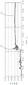
First, the measurement result of the ice surface in a state where water is not floating on the surface will be described. Fig. 8 is a graph showing the results of measuring the change in the coefficient of friction of the sole of example 1 with respect to the ice surface in a state where no water is floating on the surface. Fig. 9 is a graph showing the results of measuring the change in the coefficient of friction of the sole of comparative example 1 with respect to the ice surface in a state where no water is floating on the surface. The time on the horizontal axis of the graphs of fig. 8 and 9 represents the force F in the horizontal direction applied to the ice surface from the start in step 3 described above2The elapsed time. The same applies to the horizontal axis of the graphs in fig. 10 and 11 described later.
From the peak P in the graph of FIG. 80As can be seen from the values of (A), the maximum static friction coefficient μ of the sole of example 1 against an ice surface in a state where water is not floating on the surface0Is 0.29. Further, by finding the range R in the graph of FIG. 80Average value of (1), obtained shoe of example 1Coefficient of kinetic friction of bottom with respect to ice surface in a state where water is not floating on the surface1Is 0.39. Similarly, the maximum static friction coefficient μ of the sole of comparative example 1 against an ice surface in a state where water is not floating on the surface is obtained from the map table shown in fig. 90Coefficient of kinetic friction mu1The maximum coefficient of static friction μ00.39, and a coefficient of dynamic friction μ1Is 0.30. These results are summarized in table 1 below.
[ TABLE 1]
As can be seen from the column of "comparative example 1" in Table 1, the dynamic friction coefficient μ of the sole of comparative example 11Specific maximum coefficient of static friction mu0Small and dynamic friction coefficient mu1Relative to the maximum coefficient of static friction mu0Specific to1/μ0About 0.77. Therefore, the shoe sole of comparative example 1 can exhibit good slip resistance immediately after the shoe sole starts to stand on an ice surface, but tends to slip easily thereafter. Actually, when walking on an ice surface while wearing the shoe equipped with the sole of comparative example 1, the shoe can firmly grip the ground immediately after starting to stand stably (immediately after landing on the walking surface or immediately after starting to kick off the walking surface), but after that, the shoe tends to easily slip. From this, it is understood that even when the shoe equipped with the sole of comparative example 1, which is currently commercially available, is worn on the ice surface, the shoe is evaluated to have the most excellent slip resistance on the ice surface, and considerable attention is required. Even when the shoe equipped with the sole of comparative example 1 was worn, running on an ice surface or repeated jumping on an ice surface was difficult.
On the other hand, as can be seen from the column of "example 1" in table 1, the dynamic friction coefficient μ of the sole of example 11Maximum ratioCoefficient of static friction mu0Large and dynamic friction coefficient mu1Relative to the maximum coefficient of static friction mu0Specific to1/μ0Approximately 1.34. Further, the dynamic friction coefficient μ of the sole of example 110.39, much greater than the coefficient of dynamic friction μ of the sole of comparative example 11I.e. 0.30. Therefore, it can be said that the shoe sole of example 1 can continue to stand stably effectively not only immediately after starting to stand stably but also thereafter. In fact, when an attempt is made to walk on an ice surface while wearing the shoe sole equipped with example 1, the feeling of firmly catching the ice surface occurs until the shoe sole lands on the ice surface and separates from the ice surface. Therefore, when the shoe equipped with the sole of example 1 was worn, the user could walk with the same feeling as when walking on a dry road surface without paying special attention. When shoes equipped with the soles of example 1 were worn, running on ice or repeated jumping on ice was possible.
Next, the measurement result of the ice surface in a state where water is floating on the surface will be described. Fig. 10 is a graph showing the results of measuring the change in the coefficient of friction of the sole of example 1 with respect to the ice surface in a state where water is floating on the surface. Fig. 11 is a graph showing the results of measuring the change in the coefficient of friction of the sole of comparative example 1 with respect to the ice surface in a state where water is floating on the surface.
From the peak P in the graph of FIG. 100The maximum static friction coefficient μ of the sole of example 1 against an ice surface in a state where water was floating on the surface was found to be0Is 0.31. Further, by finding the range R in the graph of FIG. 100The obtained average value of (A), the dynamic friction coefficient μ of the sole of example 1 against an ice surface in a state where water is floating on the surface1Is 0.20. Similarly, the maximum static friction coefficient μ of the sole of comparative example 1 with respect to the ice surface in a state where water is floating on the surface is obtained from the graph shown in fig. 110Coefficient of kinetic friction mu1The maximum coefficient of static friction μ00.41, and a coefficient of dynamic friction μ1Is 0.10. These results are summarized in table 2 below.
[ TABLE 2]
| |
Maximum coefficient of static friction mu0 |
Coefficient of dynamic friction mu1 |
| Example 1
|
0.31
|
0.20
|
| Comparative example 1
|
0.41
|
0.10 |
As can be seen from the column of "comparative example 1" in Table 2, the dynamic friction coefficient μ of the sole of comparative example 11Specific maximum coefficient of static friction mu0Small and dynamic friction coefficient mu1Relative to the maximum coefficient of static friction mu0Specific to1/μ0But is about 0.24. Therefore, the sole of comparative example 1 can exhibit good slip resistance immediately after standing on ice in a state where water is floating on the surface, but thereafter tends to rapidly slide easily.
In contrast, as can be seen from the column of "example 1" in table 2, the dynamic friction coefficient μ of the sole of example 1 is larger than that of the sole of example 11Specific maximum coefficient of static friction mu0Small, but dynamic coefficient of friction mu1Relative to the maximum coefficient of static friction mu0Specific to1/μ0About 0.64, which is much larger than the ratio μ in the sole of comparative example 1 under the same conditions1/μ0Value of (3) 0.24. Further, dynamic friction of the sole of example 1Coefficient of friction mu1Even on an ice surface with water floating on the surface, the coefficient of kinetic friction μ of the sole of comparative example 1 was 0.20, and the same conditions were satisfied1Twice as much. Therefore, even on an ice surface with water floating on the surface, the sole of example 1 can exhibit more excellent slip resistance than a shoe equipped with the sole of comparative example 1, which is evaluated as the most excellent slip resistance to the ice surface among soles currently on the market.
Description of the reference numerals
10 sole main body (big bottom)
11 drainage path
20 anti-slip projection
21 concave part
22 step part
23 drainage hole
30 middle sole
31 middle sole body
32 soft middle bottom
D0Outer diameter of antiskid projection
D1Diameter of the drain hole
H0Height of the anti-slip projection
H1Height of the step
W0Width of gap between adjacent anti-slip protrusions
W1Width of step part