CN108423077B - Connection structure of stiffening beam and side wall assembly on front wheel casing - Google Patents
Connection structure of stiffening beam and side wall assembly on front wheel casing Download PDFInfo
- Publication number
- CN108423077B CN108423077B CN201810351559.7A CN201810351559A CN108423077B CN 108423077 B CN108423077 B CN 108423077B CN 201810351559 A CN201810351559 A CN 201810351559A CN 108423077 B CN108423077 B CN 108423077B
- Authority
- CN
- China
- Prior art keywords
- front wheel
- pillar
- welding
- side wall
- reinforcement plate
- Prior art date
- Legal status (The legal status is an assumption and is not a legal conclusion. Google has not performed a legal analysis and makes no representation as to the accuracy of the status listed.)
- Active
Links
Images

Classifications
-
- B—PERFORMING OPERATIONS; TRANSPORTING
- B62—LAND VEHICLES FOR TRAVELLING OTHERWISE THAN ON RAILS
- B62D—MOTOR VEHICLES; TRAILERS
- B62D27/00—Connections between superstructure or understructure sub-units
- B62D27/02—Connections between superstructure or understructure sub-units rigid
- B62D27/023—Assembly of structural joints
Landscapes
- Engineering & Computer Science (AREA)
- Chemical & Material Sciences (AREA)
- Combustion & Propulsion (AREA)
- Transportation (AREA)
- Mechanical Engineering (AREA)
- Body Structure For Vehicles (AREA)
Abstract
本发明提供一种前轮罩上加强梁和侧围总成的连接结构,解决传统结构中CO2焊点开焊或局部钣金开裂的问题,提升车身安全性和客户满意度,并且降低了单车制造成本。该连接结构包括从外到内依次贴合的前轮罩加强梁、侧围外板、A柱下加强板以及A柱上铰链加强板,A柱下加强板和A柱上铰链加强板通过点焊连接形成A柱下加强板总成,其特征在于所述A柱上铰链加强板上设有焊接过孔,焊钳通过所述焊接过孔把所述前轮罩加强梁、侧围外板和A柱下加强板总成连接在一起并通过点焊连接。

The present invention provides a connection structure of the reinforcing beam on the front wheel cover and the side wall assembly, which solves the problem of CO2 welding point welding or partial sheet metal cracking in the traditional structure, improves the safety of the vehicle body and customer satisfaction, and reduces the Bike manufacturing cost. The connecting structure includes a front wheel house reinforcement beam, side wall outer panel, A-pillar lower reinforcement plate and A-pillar upper hinge reinforcement plate, which are sequentially attached from the outside to the inside. The A-pillar lower reinforcement plate and the A-pillar upper hinge reinforcement plate pass through The A-pillar lower reinforcement plate assembly is formed by welding, which is characterized in that the upper hinge reinforcement plate of the A-pillar is provided with welding through holes, and the welding tongs pass the welding through holes to the front wheel cover reinforcement beam and the side wall outer plate. It is connected with the lower reinforcement plate assembly of the A-pillar and connected by spot welding.
Description
技术领域technical field
本发明涉及汽车车身结构技术领域,具体涉及一种前轮罩上加强梁和侧围总成的连接结构。The invention relates to the technical field of automobile body structures, in particular to a connection structure of a reinforcing beam on a front wheel cover and a side wall assembly.
背景技术Background technique
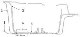
目前汽车前轮罩上加强梁是在骨架的最后工序,通过自身的塞焊孔与侧围总成用CO2焊接在一起。其结构如图1和图2所示,A柱上铰链加强板3和A柱下加强板4通过点焊连接形成A柱下加强板总成,A柱下加强板总成与侧围外板通过三层板焊接处a实现点焊连接,形成侧围外板总成,该三层板焊接处是A柱上铰链加强板3、A柱下加强板4以及侧围外板2形成三层板焊点;然后,在前轮罩上加强梁与侧围外板2在三层板焊接处a位置留有0.5mm左右的间隙,以减小骨架焊接过程中Y向偏差。最后在骨架的CO2工位,通过CO2塞焊孔10,把前轮罩上加强梁1与侧围总成烧焊在一起,形成车身骨架。侧围外板的料厚一般是0.7mm,烧焊过程中,容易把侧围外板烧穿或者局部变脆,在车辆行驶的过程中,路面带给车身的外力,会导致此处CO2开焊或局部钣金开裂,引起异响甚至钣金锈蚀的风险,车身安全性下降,客户满意度降低。CO2焊接,需要规划焊接设备,焊接工位,配备人员操作,制造工时增加,导致单车制造成本增加。At present, the reinforcing beam on the front wheel cover of the automobile is the final process of the skeleton, and it is welded together with the side wall assembly by CO 2 through its own plug welding hole. Its structure is shown in Figures 1 and 2. The upper
发明内容SUMMARY OF THE INVENTION
本发明的目的是提出一种前轮罩上加强梁和侧围总成的连接结构,解决传统结构中CO2焊点开焊或局部钣金开裂的问题,提升车身安全性和客户满意度,并且降低了单车制造成本。The purpose of the present invention is to propose a connection structure of the reinforcing beam on the front wheel cover and the side wall assembly, which solves the problems of CO2 welding point welding or partial sheet metal cracking in the traditional structure, improves the safety of the car body and the satisfaction of customers, And reduce the cost of bicycle manufacturing.
根据本发明提供的前轮罩上加强梁和侧围总成的连接结构,包括从外到内依次贴合的前轮罩加强梁、侧围外板、A柱下加强板以及A柱上铰链加强板,A柱下加强板和A柱上铰链加强板通过点焊连接形成A柱下加强板总成,其特征在于所述A柱上铰链加强板上设有焊接过孔,焊钳通过所述焊接过孔把所述前轮罩加强梁、侧围外板和A柱下加强板总成连接在一起并通过点焊连接。The connection structure of the front wheel house upper reinforcement beam and the side wall assembly provided according to the present invention includes the front wheel house reinforcement beam, the side wall outer plate, the A-pillar lower reinforcement plate and the A-pillar upper hinge, which are sequentially fitted from outside to inside. The reinforcement plate, the A-pillar lower reinforcement plate and the A-pillar upper hinge reinforcement plate are connected by spot welding to form the A-pillar lower reinforcement plate assembly. The welding vias connect the front wheel house reinforcing beam, the side wall outer plate and the A-pillar lower reinforcing plate assembly together and are connected by spot welding.
本发明通过在A柱上铰链加强板上设置焊接过孔,焊钳通过焊接过孔把前轮罩加强梁、侧围外板和A柱下加强板总成连接在一起并通过点焊连接,从而实现前轮罩加强梁、侧围外板和A柱下加强板总成的三层板点焊连接,在车辆行驶的过程中,路面带给车身的外力,通过此处三层板焊点传给侧围总成,实现力的有效传递,减小此处受力。可见,本发明通过解决传统骨架结构中前轮罩上加强梁与侧围外板总成点焊无法实现的问题,避免了CO2带来的焊点开焊或局部钣金开裂的问题,也就避免了CO2焊接的质量问题,提高了生产率,同时缩短生产节拍,降低单车制造成本。In the present invention, a welding through hole is arranged on the upper hinge reinforcement plate of the A column, and the welding tongs connect the front wheel cover reinforcement beam, the side wall outer plate and the lower reinforcement plate assembly of the A column together through the welding through hole, and are connected by spot welding, In this way, the three-layer spot welding connection of the front wheel cover reinforcing beam, the side wall outer plate and the A-pillar lower reinforcing plate assembly is realized. During the driving process of the vehicle, the external force brought by the road surface to the body passes through the three-layer plate welding point here. It is transmitted to the side wall assembly to realize the effective transmission of force and reduce the force here. It can be seen that the present invention solves the problem that spot welding of the reinforcing beam on the front wheel cover and the side wall outer plate assembly cannot be realized in the traditional skeleton structure, avoids the problem of welding spot welding or partial sheet metal cracking caused by CO 2 , and also It avoids the quality problem of CO 2 welding, improves productivity, shortens the production cycle, and reduces the cost of single-vehicle manufacturing.
进一步的,所述焊接过孔设置在所述前轮罩加强梁沿x向的搭接区域内,以保证三层板焊点处力的有效传递。Further, the welding via holes are arranged in the overlapping area of the front wheel house reinforcing beam along the x-direction, so as to ensure the effective transmission of the force at the welding point of the three-layer board.
进一步的,所述焊接过孔设置有多个且沿z向均匀间隙设置,以保证焊接质量。Further, the welding via holes are provided with a plurality of uniform gaps along the z-direction, so as to ensure the welding quality.
进一步的,所述前轮罩加强梁的搭接区域的z向边缘呈波浪状,该波浪状边缘围成的波峰区域对应所述焊接过孔的位置。这样的结构可以保证三层板焊接处具有一定的压溃吸能效果,减少碰撞变形,提高安全性。Further, the z-direction edge of the overlapping area of the front wheel house reinforcing beam is wavy, and the wave crest area enclosed by the wavy edge corresponds to the position of the welding via hole. Such a structure can ensure that the welding part of the three-layer board has a certain crushing energy absorption effect, reduce collision deformation, and improve safety.
进一步的,所述A柱上铰链加强板设有沿y向与所述A柱下加强板配合的搭接边,以提升A柱上铰链加强板的结构加强力度。Further, the upper hinge reinforcement plate of the A-pillar is provided with a lap joint that cooperates with the lower reinforcement plate of the A-pillar in the y direction, so as to enhance the structural reinforcement of the upper hinge reinforcement plate of the A-pillar.
进一步的,所述前轮罩加强梁的搭接区域与所述前轮罩加强梁的x向前端之间设有弯折过渡,以使前轮罩加强梁的搭接处具有一定的碰撞压溃吸能效果。Further, a bending transition is provided between the overlapping area of the front wheel house reinforcing beam and the x-direction front end of the front wheel house reinforcing beam, so that the lap joint of the front wheel house reinforcing beam has a certain collision pressure. Crash energy effect.
具体的说,所述前轮罩加强梁、侧围外板、A柱下加强板以及A柱上铰链加强板均为冲压成型。Specifically, the front wheel house reinforcement beam, the side wall outer plate, the A-pillar lower reinforcement plate and the A-pillar upper hinge reinforcement plate are all stamped and formed.
附图说明Description of drawings
图1为传统前轮罩上加强梁和侧围总成的连接结构示意图。FIG. 1 is a schematic diagram of the connection structure of the reinforcing beam on the traditional front wheel cover and the side wall assembly.
图2为图1的局部结构放大图。FIG. 2 is an enlarged view of a partial structure of FIG. 1 .
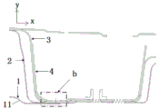
图3为本发明的前轮罩上加强梁和侧围总成的连接结构示意图。FIG. 3 is a schematic diagram of the connection structure of the reinforcement beam on the front wheel cover and the side wall assembly of the present invention.
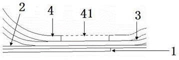
图4为图3的局部结构放大图。FIG. 4 is an enlarged view of a partial structure of FIG. 3 .
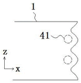
图5为前轮罩上加强梁的y向搭接区域局部结构示意图。FIG. 5 is a schematic diagram of the partial structure of the y-direction overlapping area of the reinforcing beam on the front wheel cover.
具体实施方式Detailed ways
下面对照附图,通过对实施实例的描述,对本发明的具体实施方式如所涉及的各构件的形状、构造、各部分之间的相互位置及连接关系、各部分的作用及工作原理等作进一步的详细说明。With reference to the accompanying drawings, the specific embodiments of the present invention, such as the shape and structure of each component involved, the mutual position and connection relationship between each part, the function and working principle of each part, etc. detailed description.
如图3、4,本发明的前轮罩上加强梁和侧围总成的连接结构,包括从外到内依次贴合的前轮罩加强梁1、侧围外板2、A柱下加强板3以及A柱上铰链加强板4,A柱下加强板3和A柱上铰链加强板4通过点焊连接形成A柱下加强板总成, A柱上铰链加强板上设有焊接过孔41,焊钳通过焊接过孔41把前轮罩加强梁1、侧围外板2和A柱下加强板总成连接在一起并通过点焊连接。As shown in Figures 3 and 4, the connection structure of the front wheel cover upper reinforcement beam and the side wall assembly of the present invention includes the front wheel
本发明通过在A柱上铰链加强板4上设置焊接过孔41,焊钳通过焊接过孔41把前轮罩加强梁1、侧围外板2和A柱下加强板总成连接在一起并通过点焊连接,从而实现前轮罩加强梁1、侧围外板2和A柱下加强板总成的三层板点焊连接,在车辆行驶的过程中,路面带给车身的外力,通过此处三层板焊点b传给侧围总成,实现力的有效传递,减小此处受力。可见,本发明通过解决传统骨架结构中前轮罩上加强梁与侧围外板总成点焊无法实现的问题,避免了CO2带来的焊点开焊或局部钣金开裂的问题,也就避免了CO2焊接的质量问题,提高了生产率,同时缩短生产节拍,降低单车制造成本。In the present invention, a welding through
作为优选的实施方式,焊接过孔41设置在前轮罩加强梁1沿x向的搭接区域内,以保证三层板焊点处力的有效传递。As a preferred embodiment, the welding through
优选的,焊接过孔41设置有多个且沿z向均匀间隙设置,以保证焊接质量。Preferably, a plurality of
优选的,前轮罩加强梁1的搭接区域的z向边缘呈波浪状,该波浪状边缘围成的波峰区域对应焊接过孔41的位置,如图5所示。这样的结构可以保证三层板焊接处b具有一定的压溃吸能效果,减少碰撞变形,提高安全性。Preferably, the z-direction edge of the overlapping area of the front wheel
优选的,A柱上铰链加强板4设有沿y向与A柱下加强板3配合的搭接边42,以提升A柱上铰链加强板4的结构加强力度。Preferably, the upper
优选的,前轮罩加强梁1的搭接区域与前轮罩加强梁1的x向前端之间设有弯折过渡11,以使前轮罩加强梁1的搭接处具有一定的碰撞压溃吸能效果。Preferably, a
具体的说,前轮罩加强梁1、侧围外板2、A柱下加强板3以及A柱上铰链加强板4均为冲压成型。Specifically, the front wheel
Claims (4)
Priority Applications (1)
| Application Number | Priority Date | Filing Date | Title |
|---|---|---|---|
| CN201810351559.7A CN108423077B (en) | 2018-04-19 | 2018-04-19 | Connection structure of stiffening beam and side wall assembly on front wheel casing |
Applications Claiming Priority (1)
| Application Number | Priority Date | Filing Date | Title |
|---|---|---|---|
| CN201810351559.7A CN108423077B (en) | 2018-04-19 | 2018-04-19 | Connection structure of stiffening beam and side wall assembly on front wheel casing |
Publications (2)
| Publication Number | Publication Date |
|---|---|
| CN108423077A CN108423077A (en) | 2018-08-21 |
| CN108423077B true CN108423077B (en) | 2020-10-09 |
Family
ID=63161330
Family Applications (1)
| Application Number | Title | Priority Date | Filing Date |
|---|---|---|---|
| CN201810351559.7A Active CN108423077B (en) | 2018-04-19 | 2018-04-19 | Connection structure of stiffening beam and side wall assembly on front wheel casing |
Country Status (1)
| Country | Link |
|---|---|
| CN (1) | CN108423077B (en) |
Families Citing this family (2)
| Publication number | Priority date | Publication date | Assignee | Title |
|---|---|---|---|---|
| CN109080703A (en) * | 2018-08-31 | 2018-12-25 | 安徽江淮汽车集团股份有限公司 | Body side wall structure |
| CN115384629A (en) * | 2022-08-29 | 2022-11-25 | 奇瑞汽车股份有限公司 | Automobile front wheel cover upper stiffening beam assembly and welding process thereof |
Citations (6)
| Publication number | Priority date | Publication date | Assignee | Title |
|---|---|---|---|---|
| JP2014145268A (en) * | 2013-01-28 | 2014-08-14 | Hitachi Constr Mach Co Ltd | Variable displacement swash plate type hydraulic rotary machine |
| JP2014148230A (en) * | 2013-01-31 | 2014-08-21 | Toyoda Gosei Co Ltd | Pedestrian airbag device |
| CN204184460U (en) * | 2014-10-29 | 2015-03-04 | 阿尔特汽车技术股份有限公司 | The connection structure of strength beam on front wheel housing |
| CN204713216U (en) * | 2015-06-12 | 2015-10-21 | 广州汽车集团股份有限公司 | Automobile rear wall structure and rear end panel assembly thereof |
| CN105329320A (en) * | 2015-11-23 | 2016-02-17 | 奇瑞汽车股份有限公司 | Impact force transmission mechanism in front of car body |
| CN206307131U (en) * | 2016-11-25 | 2017-07-07 | 上汽通用五菱汽车股份有限公司 | It is a kind of to bias the A -pillar structure for touching high security |
-
2018
- 2018-04-19 CN CN201810351559.7A patent/CN108423077B/en active Active
Patent Citations (6)
| Publication number | Priority date | Publication date | Assignee | Title |
|---|---|---|---|---|
| JP2014145268A (en) * | 2013-01-28 | 2014-08-14 | Hitachi Constr Mach Co Ltd | Variable displacement swash plate type hydraulic rotary machine |
| JP2014148230A (en) * | 2013-01-31 | 2014-08-21 | Toyoda Gosei Co Ltd | Pedestrian airbag device |
| CN204184460U (en) * | 2014-10-29 | 2015-03-04 | 阿尔特汽车技术股份有限公司 | The connection structure of strength beam on front wheel housing |
| CN204713216U (en) * | 2015-06-12 | 2015-10-21 | 广州汽车集团股份有限公司 | Automobile rear wall structure and rear end panel assembly thereof |
| CN105329320A (en) * | 2015-11-23 | 2016-02-17 | 奇瑞汽车股份有限公司 | Impact force transmission mechanism in front of car body |
| CN206307131U (en) * | 2016-11-25 | 2017-07-07 | 上汽通用五菱汽车股份有限公司 | It is a kind of to bias the A -pillar structure for touching high security |
Also Published As
| Publication number | Publication date |
|---|---|
| CN108423077A (en) | 2018-08-21 |
Similar Documents
| Publication | Publication Date | Title |
|---|---|---|
| US11584464B2 (en) | Methods for producing a three-dimensional vehicle door frame inner reinforcement element, for producing a vehicle door frame and for producing a vehicle reinforcement structure | |
| CN103228392B (en) | Formed member and method of manufacturing the same | |
| CN212499831U (en) | Integral hot stamping door ring | |
| US10167023B2 (en) | Vehicle underbody structure and vehicle body | |
| CN113276954A (en) | Thermal forming laser tailor-welding integrated door ring and processing method | |
| CN105873715B (en) | Lap welding method, lap joint, manufacturing method of lap joint, and automotive parts | |
| US10239105B2 (en) | Blank steel plate, production method and production device therefor, and production method for press-formed product using blank steel plate | |
| KR20210024592A (en) | Structure frame on the side of the vehicle body | |
| CN103158781A (en) | Reinforcement for a vehicle pillar, especially a B pillar | |
| JP2019098952A (en) | Vehicle side part vehicle body structure and manufacturing method of vehicle pillar member | |
| CN102826128A (en) | Vehicle pillar assembly | |
| CN105015623A (en) | Body in white bend resistance structure and arrangement mode thereof | |
| CN203739992U (en) | Front longitudinal girder rear structure for automobile | |
| EP2877388A1 (en) | B-pillar and method of manufacturing it | |
| US20220048454A1 (en) | Bumper beam having steel reinforcement | |
| KR20170058938A (en) | Reinforcement element for a vehicle, method for producing the same and door assembly | |
| CN102300761A (en) | Vehicle body construction in the region of the a-pillar and the window crossmember and associated production method | |
| EP3936414B1 (en) | Vehicle frame member | |
| CN104108426A (en) | Structure and method for coupling side structures and roof rails | |
| JP6284899B2 (en) | Bumper reinforcement | |
| CN207338904U (en) | The low pressure cabinet frame work of no-welding | |
| JP7350489B2 (en) | Vehicle structural components | |
| JP2022129059A (en) | Structural member for vehicle | |
| CN217893041U (en) | Side wall reinforcing plate, vehicle body frame assembly and vehicle | |
| JP2018122733A (en) | Pillar components for vehicles |
Legal Events
| Date | Code | Title | Description |
|---|---|---|---|
| PB01 | Publication | ||
| PB01 | Publication | ||
| SE01 | Entry into force of request for substantive examination | ||
| SE01 | Entry into force of request for substantive examination | ||
| GR01 | Patent grant | ||
| GR01 | Patent grant |