Anti-cracking method for paving facing layer on floor heating and floor heating paving structure
Technical Field
The invention relates to the technical field of floor heating pavement, in particular to a crack resistance method for a veneer layer paved on the floor heating and a floor heating pavement structure.
Background
With the improvement of living standard of people, in northern areas of China, in order to resist severe cold in winter, a plurality of families can install floor heating during decoration. Wherein, according to the difference of the medium that generates heat, ground warms up and mainly divide into electric heating and hot-water heating, because the hot-water heating has the advantage that the cost is low, long service life and thermal stability are good compared in the electric heating, consequently adopts the mode of hot-water heating to use more extensively.
At present, the traditional water heating pipe is mainly paved in a ground heating layer, and then a cement layer and a finish coat are paved on the heating layer in sequence. The rapid variation of the internal stress of the floor heating is easily caused due to the large temperature difference before and after the floor heating is used, so that the situation that the veneer layer cracks or breaks is easily caused, the quality reliability of the ground paving engineering is greatly influenced, and great challenges are brought to the maintenance work after the veneer layer breaks.
Disclosure of Invention
The embodiment of the invention discloses a crack resistance method for a ground heating paving facing layer and a ground heating paving structure, which can effectively prevent the facing layer from being cracked or cracked due to the expansion and contraction of hot air of ground heating and are beneficial to ensuring the quality reliability of ground paving engineering.
In order to achieve the above object, in a first aspect, the embodiments of the present invention disclose a method for resisting tension cracking of a warm-laying finishing layer, the method comprising the steps of:
paving the stirred cement mortar on the ground to form a cement mortar layer;
providing a plurality of separating rods and a plurality of telescopic strips which are consistent with the extending directions of the separating rods;
the plurality of separation rods are sequentially arranged on the cement mortar layer at intervals, the telescopic strips are arranged on the cement mortar layer, and each telescopic strip is positioned on one side of each separation rod;
pressing the separation rods and the telescopic strips into the cement mortar layer so that the cement mortar layer covers the separation rods and the telescopic strips;
paving a finish coat on the cement mortar layer;
and drawing the separating rods out of the paved facing layer so as to form a plurality of through grooves in the cement mortar layer.
Wherein, the telescopic strip is a plastic foam strip or a plastic rod.
As an optional implementation manner, in an embodiment of the first aspect of the present invention, in the step of sequentially arranging the plurality of separation rods at intervals on the cement mortar layer, and arranging the expansion strips on the cement mortar layer such that each expansion strip is located on one side of each separation rod, the method specifically includes:
a plurality of grooves which are arranged at intervals are arranged on the cement mortar layer;
uniformly coating cement oil in the groove;
placing each separating rod and each expansion strip in each groove respectively;
wherein, be the equidistance setting between two adjacent recesses.
As an alternative implementation, in an embodiment of the first aspect of the present invention, the groove is a U-shaped groove or a square-shaped groove.
As an alternative implementation, in an embodiment of the first aspect of the invention,
before the step of laying the mixed cement mortar on the ground to form a cement mortar layer, the method further comprises:
sprinkling water on the ground;
and adhering the plain cement on the ground by adopting a slurry sweeping tool to sweep the plain cement uniformly on the ground so as to ensure that the ground is uniformly full of the plain cement.
In an alternative embodiment, in the embodiment of the first aspect of the present invention, the separating rods are PVC pipes, and the diameter of each separating rod is 15-25 mm.
In an alternative embodiment, in the first aspect of the present invention, the distance between two adjacent separating rods is in a range of 800 to 1200 mm.
As an optional implementation manner, in an embodiment of the first aspect of the present invention, the finishing layer is stone or ceramic tile, and the thickness of the finishing layer is 50 to 80 mm.
As an optional implementation manner, in an embodiment of the first aspect of the present invention, the plurality of separation rods are sequentially arranged at intervals along a width direction of the ground, and an extending direction of each separation rod is consistent with a length extending direction of the ground.
In a second aspect, the invention also discloses a floor heating paving structure, which comprises a cement mortar layer arranged on the ground and a finish coat arranged on the cement mortar layer, wherein a plurality of through grooves and a plurality of telescopic strips arranged corresponding to the through grooves are arranged in the cement mortar layer, the through grooves are sequentially arranged at intervals, the through grooves extend along the length direction of the cement mortar layer, and each telescopic strip is respectively arranged outside each through groove.
As an alternative implementation manner, in the embodiment of the second aspect of the present invention, the opening direction of each through groove is perpendicular to the upper surface of the cement mortar layer, and the centers of the through grooves are located on the same straight line.
As an optional implementation manner, in an embodiment of the second aspect of the present invention, a distance between each expansion strip and an outer wall of the through slot disposed corresponding to the expansion strip is in a range of 0 to 5 mm.
Compared with the prior art, the invention has the following beneficial effects:
according to the anti-cracking method for paving the finish coat on the floor heating and the floor heating paving structure provided by the embodiment of the invention, the plurality of separating rods and the plurality of telescopic strips arranged corresponding to the plurality of separating rods are arranged in the cement mortar layer, and the separating rods and the telescopic strips are compacted in the cement mortar layer, so that when the finish coat is paved on the cement mortar layer, the separating rods can be pulled out, and a plurality of through grooves are formed in the cement mortar layer. By adopting the arrangement mode, when hot gas is diffused from the heat transfer layer to the cement mortar layer, the hot gas can pass through the through groove in the cement mortar layer, so that the hot gas can directly circulate, and the situation that the veneer layer above the cement mortar layer cracks or breaks due to direct expansion caused by thermal expansion and cold contraction is avoided; in addition, the adoption sets up the telescopic strip in the outside that leads to the groove, and the flexible characteristic that can effectively utilize the telescopic strip to have makes to have certain flexible surplus between the adjacent finish coat to further be convenient for provide sufficient flexible surplus and effectively prevent that the finish coat from producing crack or fracture when steam expend with heat and contract with cold, effectively ensure the quality of ground shop and paste the engineering, also spread to paste to maintain for follow-up ground simultaneously and reduced a large amount of work load.
Drawings
In order to more clearly illustrate the technical solutions in the embodiments of the present invention, the drawings needed to be used in the embodiments will be briefly described below, and it is obvious that the drawings in the following description are only some embodiments of the present invention, and it is obvious for those skilled in the art that other drawings can be obtained according to these drawings without creative efforts.
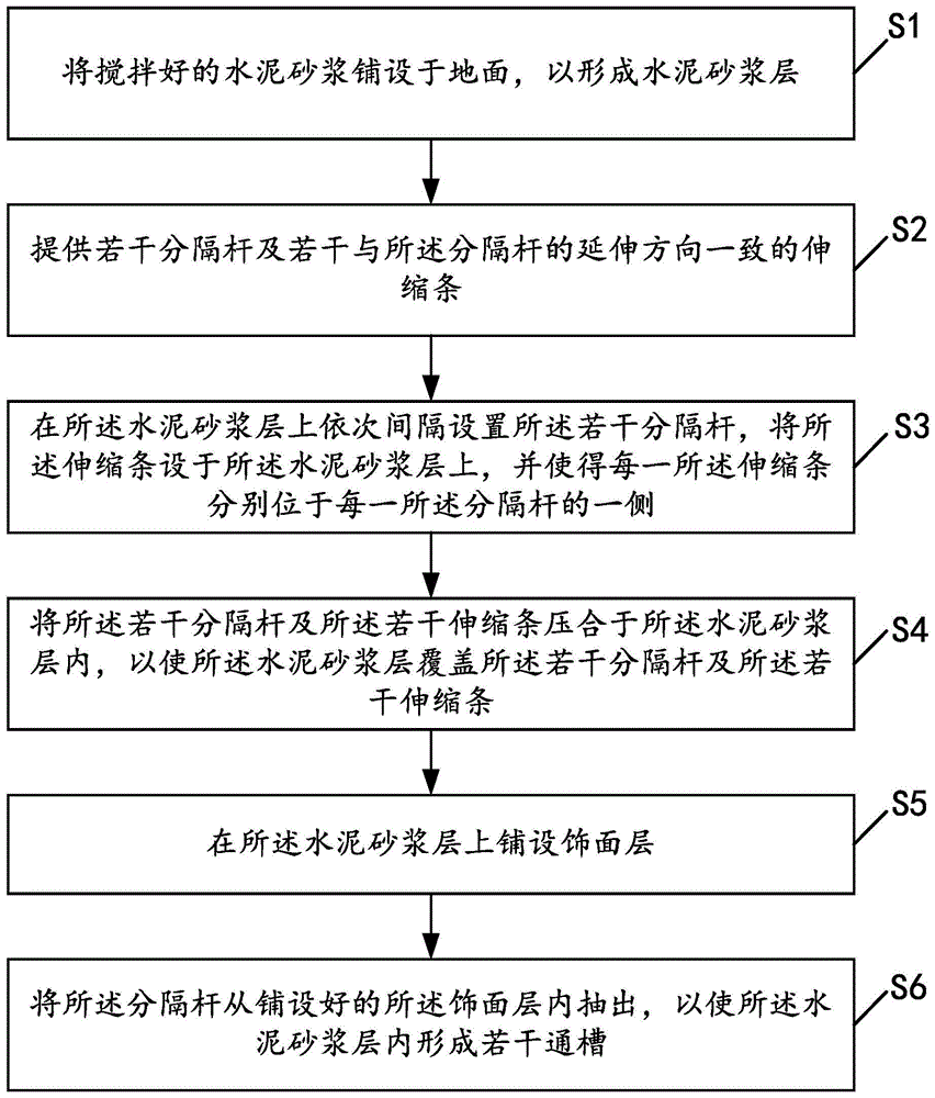
FIG. 1 is a flow chart of a method for preventing stretch cracking of a finishing layer for floor heating according to one embodiment of the present invention;
fig. 2 is a schematic structural view of a floor heating paving structure disclosed in the second embodiment of the invention.
Detailed Description
The technical solutions in the embodiments of the present invention will be clearly and completely described below with reference to the drawings in the embodiments of the present invention, and it is obvious that the described embodiments are only a part of the embodiments of the present invention, and not all of the embodiments. All other embodiments, which can be derived by a person skilled in the art from the embodiments given herein without making any creative effort, shall fall within the protection scope of the present invention.
In the present invention, the terms "upper", "lower", "left", "right", "front", "rear", "top", "bottom", "inner", "outer", "center", "vertical", "horizontal", "lateral", "longitudinal", and the like indicate an orientation or positional relationship based on the orientation or positional relationship shown in the drawings. These terms are used primarily to better describe the invention and its embodiments and are not intended to limit the indicated devices, elements or components to a particular orientation or to be constructed and operated in a particular orientation.
Moreover, some of the above terms may be used to indicate other meanings besides the orientation or positional relationship, for example, the term "on" may also be used to indicate some kind of attachment or connection relationship in some cases. The specific meanings of these terms in the present invention can be understood by those skilled in the art as appropriate.
Furthermore, the terms "mounted," "disposed," "provided," "connected," and "connected" are to be construed broadly. For example, it may be a fixed connection, a removable connection, or a unitary construction; can be a mechanical connection, or an electrical connection; may be directly connected, or indirectly connected through intervening media, or may be in internal communication between two devices, elements or components. The specific meanings of the above terms in the present invention can be understood by those of ordinary skill in the art according to specific situations.
Furthermore, the terms "first," "second," and the like, are used primarily to distinguish one device, element, or component from another (the specific nature and configuration may be the same or different), and are not used to indicate or imply the relative importance or number of the indicated devices, elements, or components. "plurality" means two or more unless otherwise specified.
The following detailed description is made with reference to the accompanying drawings.
Example one
Fig. 1 is a flowchart of a method for preventing a floor heating pavement facing layer from cracking, according to an embodiment of the present invention. The anti-cracking method comprises the following steps:
s1: and paving the stirred cement mortar on the ground to form a cement mortar layer.
The method aims to finish the laying of the cement mortar layer on the ground firstly and lay a foundation for the subsequent laying of the finish coat.
In this step, after the cement mortar is uniformly mixed by a mixing tool (such as a shovel or a special cement mixing device), the cement mortar is laid on the ground (such as a room ground or a hall ground) where the finishing layer is to be laid, and the cement mortar is tightly compacted on the ground by a compacting device, so as to form a uniform cement mortar layer. That is, after the mixed cement mortar is laid on the ground, the cement mortar should be compacted to form a uniform and strong cement mortar layer. It should be understood that, when the cement mortar is compacted on the ground, the height and uniformity of each formed cement mortar layer should be kept consistent, so as to ensure the flatness of each veneer layer when the veneer layers are subsequently laid on the cement mortar layer.
Further, in order to ensure that the cement mortar layer can be tightly compacted on the ground when the cement mortar layer is laid, the following processes may be performed before the step S1:
sprinkling water on the ground, and then using a slurry sweeping tool to stick the plain cement to sweep uniformly on the ground so as to make the plain cement uniformly adhered on the ground. By adopting the processing mode, the ground can be in a semi-wet state, so that cement mortar can be well adhered to the ground when the subsequent cement mortar is conveniently laid.
S2: and providing a plurality of separating rods and a plurality of telescopic strips which are consistent with the extending direction of the separating rods.
In this embodiment, the separating rods are all PVC pipes, and the diameter of each separating rod is 15-25 mm. Preferably, the rod diameter of the separation rod can be 20mm, so that a round hole with the diameter of 20mm can be left on the cement mortar layer when the separation rod is subsequently pulled out. It will be appreciated that in other embodiments the spacer rod may also be a steel tube and the rod diameter of the spacer rod may also be 15mm or 25mm etc.
S3: the separation rods are sequentially arranged on the cement mortar layer at intervals, the telescopic strips are arranged on the cement mortar layer, and each telescopic strip is located on one side of each separation rod.
In this embodiment, the distance between two adjacent separation rods may be in a range of 800-1200 mm, that is, when the plurality of separation rods are disposed, the plurality of separation rods may be sequentially disposed at intervals along the width direction of the cement mortar layer (which is the same as the width direction of the ground) in terms of the width extending direction of the cement mortar layer, the extending direction of each separation rod is the same as the length extending direction of the cement mortar layer (i.e., the length extending direction of the ground), and the distances between two adjacent separation rods are equal, so that the separation rods can divide the cement mortar layer into a plurality of regions with equal areas in the width direction of the cement mortar layer. Preferably, the distance between two adjacent separating rods can be set according to the width of the finish coat arranged on the cement mortar layer, for example, when the width of the finish coat is 1200mm, the distance between two adjacent separating rods can be 1200mm, so that after the finish coat is laid, a gap formed by the separating rods can be formed between two adjacent finish coats to allow hot air to pass through, and the influence of thermal expansion and cold contraction of the floor heating on the finish coat is avoided. It will be appreciated that the distance between two adjacent spacer rods may be 800mm, 900mm, 1000mm or 1100mm, etc.
Further, because the length extending direction of the telescopic strip is consistent with the length extending direction of the partition rod, the length extending direction of the telescopic strip is consistent with the length extending direction of the cement mortar layer.
Furthermore, when the plurality of separation rods and the expansion strips are arranged on the cement mortar layer, the following modes can be specifically included:
the cement mortar layer is provided with a plurality of grooves arranged at intervals, cement oil is uniformly coated in the grooves, and each separating rod and each telescopic strip are respectively placed in the same groove. Specifically, the groove can be a U-shaped groove or a square groove, and the groove width of the groove should be slightly larger than the widths of the separation rod and the telescopic bar so as to facilitate the placement of the separation rod and the telescopic bar. In addition, the grooves are uniformly coated with cement oil, so that cement mortar in the grooves is in a wet state, and the separating rods and the telescopic strips can be conveniently compacted in the cement mortar after the separating rods and the telescopic strips are placed.
S4: and pressing the separation rods and the telescopic strips in the cement mortar layer so that the cement mortar layer covers the separation rods and the telescopic strips.
The purpose of this step is to bury separating rod and expansion bar firmly in the cement mortar layer. In particular, a compacting tool (e.g., a shovel, etc.) may be used to tightly compact the cement mortar on the spacer bars and the telescopic bars, at which time the grooves are filled.
S5: and paving a finishing coat on the cement mortar layer.
In this embodiment, the finishing layer may be stone or ceramic tile, and the thickness of the finishing layer may be 50-80 mm. Preferably, the facing layer has a thickness of 60 mm. It is understood that in other embodiments, the facing layer may also have a thickness of 50mm, 70mm, 80mm, or the like.
S6: and drawing the separating rods out of the paved facing layer so as to form a plurality of through grooves in the cement mortar layer.
The purpose of this step is to extract the spacer bars from the cement mortar bed so that a plurality of through slots are formed in the cement mortar bed. Because this logical groove is for setting up in cement mortar in situ, consequently this a plurality of logical groove can supply the circulation of steam in the ground warms up to avoid warm up to produce high temperature thermal barrier shrinkage and lead to the finish coat to produce the condition of crack or fracture.
Specifically, in order to conveniently pull out the separation rod, when the finish coat is laid on the cement mortar layer, after the finish coat at the current position is laid, the laying work of the finish coat at the next position can be prepared, after the laying work at the next position is prepared, the separation rod below the finish coat at the current position can be pulled out, and the expansion strip continues to be left in the cement mortar layer. In this way, the partition rod can be conveniently drawn out, and the situation that the through groove is blocked due to the fact that cement mortar enters the through groove and possibly caused by the fact that the partition rod is drawn out due to the fact that the veneer layer is laid for a short time can be prevented.
According to the anti-cracking method for the floor heating pavement finish coat, the plurality of separating rods and the plurality of telescopic strips are arranged in the cement mortar layer, the separating rods are pulled out after the finish coat is paved, so that the plurality of through grooves for hot air to circulate are formed in the cement mortar layer, and meanwhile, the telescopic strips have certain telescopic allowance, so that enough space can be provided for expansion when the floor heating is expanded due to heat expansion and cold contraction, the condition that cracks or fractures are caused to the finish coat paved on the cement mortar layer is avoided, and the paving quality of the floor heating pavement finish coat is effectively ensured.
Example two
Fig. 2 is a schematic structural diagram of a floor heating paving structure according to a second embodiment of the present invention. The floor heating paving structure 100 comprises a cement mortar layer 20 paved on the ground 10 and a finish coat 30 paved above the cement mortar layer 20. Wherein, be provided with a plurality of logical grooves 21 in this cement mortar layer 20 and correspond a plurality of expansion strips 22 that these a plurality of logical grooves 21 set up, these a plurality of logical grooves 21 set up at the interval in proper order, and each leads to groove 2141 and all extends along the length direction on cement mortar layer 20, and each outside that leads to groove 21 is located respectively to each expansion strip 22.
By adopting the arrangement mode, the through groove 21 formed in the cement mortar layer 20 can be used for hot air to pass through, so that the effect of hot air expansion and contraction on the finish coat 30 positioned above the cement mortar layer 20 is effectively reduced; in addition, the adoption sets up the telescopic strip 22 outside leading to groove 21, utilizes the flexible characteristic that telescopic strip 22 has, can further make to have good flexible surplus between the adjacent cement mortar layer 20 to effectively prevent that steam inflation and cause the condition of crack or fracture to finish coat 30.
In this embodiment, the distances between two adjacent through grooves 21 are equal, and the center distance between the two adjacent through grooves 21 is based on the width of the finish layer 30 disposed on the cement mortar layer 20, for example, when the width of each finish layer 30 disposed on the cement mortar layer 20 is 1 to 1.5m, the center distance between the two adjacent through grooves 21 can be correspondingly set to 1 to 1.5m, so that the through grooves 21 disposed between the two adjacent finish layers 30 can effectively allow the hot air to pass through, and the crack generation of the finish layer 30 caused by the direct expansion of the hot air is avoided. Specifically, the through groove 21 may be a circular groove, and the diameter of the through groove 21 is 15-25 mm. Preferably, the aperture of the through slot 21 is 15 mm. It is understood that in other embodiments, the aperture of the through slot 21 may also be set according to the actual construction situation, for example, 20mm or 25 mm.
Further, the opening direction of each through groove 21 is perpendicular to the upper surface of the cement mortar layer 20, and the centers of the through grooves 21 are located on the same straight line. Specifically, the through slots 21 can be formed in the cement mortar layer 20 by providing a plurality of tubular structures on the cement mortar layer 20 before the facing layer 30 is laid, then compacting the tubular structures in the cement mortar layer 20 and ensuring that the cement mortar layer 20 completely covers the tubular structures, and then drawing out the tubular structures after the facing layer 30 is laid.
In the present embodiment, the expansion strip 22 is disposed adjacent to the through slot 21, and the length extending direction of the expansion strip 22 is identical to the length extending direction of the through slot 21. That is, when the through groove 21 is formed in such a manner that a tubular structure (e.g., a general water pipe) is provided in the cement mortar layer 20 at the time of construction, the expansion bar 22 may be placed at one side of the tubular structure, and then the tubular structure and the expansion bar 22 are compacted together in the cement mortar layer 20, and it is ensured that the cement mortar layer 20 completely covers the tubular structure and the expansion bar 22. When the facing layer 30 is laid subsequently and the tubular structure is pulled out, the expansion strip 22 is left in the cement mortar layer 20, so that a sufficient expansion allowance can be provided between two adjacent facing layers 30, hot air has a sufficient expansion space, and the facing layers 30 are prevented from being affected by direct expansion.
Further, the expansion strip 22 may be a plastic foam strip or a foam rod, and the distance between the expansion strip 22 and the outer wall of the through slot 21 corresponding to the expansion strip is 10 mm. That is, the expansion strip 22 may have a slight gap from the outer wall of the through slot 21. Specifically, during construction, a groove is dug in the cement mortar layer 20, the tubular structure and the expansion bar 22 are placed in the groove and compacted, and then the groove is filled, so that the tubular structure and the expansion bar 22 are firmly buried in the cement mortar layer 20. In this way, the tubular structure and the retractable strip 22 can be conveniently placed, and the distance range between the retractable strip 22 and the through groove 21 is within the originally set range after the tubular structure is subsequently pulled out to form the through groove 21. It is understood that, in other embodiments, the distance between the expansion strip 22 and the outer wall of the through slot 21 disposed corresponding to the expansion strip may also be adjusted according to actual construction conditions.
In this embodiment, the finishing layer 30 may be stone or ceramic tile disposed on the cement mortar layer 20, and the thickness of the finishing layer 30 may be 50-80 mm. Preferably, the facing layer 30 may have a thickness of 60 mm. It is understood that in other embodiments, the facing layer 30 may also have a thickness of 50mm, 70mm, or 80mm, etc.
In this embodiment, the floor heating paving structure 100 further includes an insulating layer 40 and a heat transfer layer 50 sequentially stacked on the ground 10, and the cement mortar layer 20 is disposed on the heat transfer layer 50. The heat-insulating layer 40 is provided with a plurality of grooves 42 with upward openings for placing the ground heating pipes 41, and the upper surfaces of the ground heating pipes 41 placed in the grooves 42 are in direct contact with the heat transfer layer 50. With this arrangement, the heat transfer layer 50 can directly transfer the heat of the floor heating pipe 41 to the cement mortar layer 20 and the finishing layer 30, thereby achieving the effect of heat transfer.
Further, in order to further facilitate heat transfer, a plurality of fins (not shown) are provided on a surface of the heat transfer layer 50 contacting the floor heating pipes 41, and the heat of the floor heating pipes 41 is uniformly transferred to each position of the heat transfer layer 50 by the fins, so that heat transfer is more uniform and heat transfer efficiency is effectively improved.
In the floor heating paving structure 100 provided by the second embodiment of the invention, the plurality of through grooves 21 and the plurality of telescopic strips 22 arranged corresponding to the plurality of through grooves 21 are arranged in the cement mortar layer 20, the plurality of through grooves 21 are sequentially arranged at intervals, and the plurality of telescopic strips 22 are arranged outside the through grooves 21. By adopting the arrangement mode, when hot air is diffused from the heat transfer layer 50 to the cement mortar layer 20, the hot air can pass through the through groove 21 in the cement mortar layer 20, so that the hot air can directly circulate, and the condition that the veneer layer 30 positioned above the cement mortar layer 20 is cracked or fractured due to direct expansion caused by thermal expansion and cold contraction is avoided; in addition, the adoption sets up the telescopic strip 22 in the outside of leading to groove 21, and the flexible characteristic that can effectively utilize telescopic strip 22 to have makes certain flexible surplus between the adjacent finish coat 30 to further be convenient for provide sufficient flexible surplus and effectively prevent finish coat 30 to produce crack or fracture when steam expend with heat and contract with cold, effectively ensure the quality of ground 10 shop's engineering, also laid for follow-up ground 10 simultaneously and maintained and reduced a large amount of work load.
According to the anti-cracking method for paving the finish coat on the floor heating and the floor heating paving structure provided by the embodiment of the invention, the plurality of separating rods and the plurality of telescopic strips arranged corresponding to the plurality of separating rods are arranged in the cement mortar layer, and the separating rods and the telescopic strips are compacted in the cement mortar layer, so that when the finish coat is paved on the cement mortar layer, the separating rods can be pulled out, and a plurality of through grooves are formed in the cement mortar layer. By adopting the arrangement mode, when hot gas is diffused from the heat transfer layer to the cement mortar layer, the hot gas can pass through the through groove in the cement mortar layer, so that the hot gas can directly circulate, and the situation that the veneer layer above the cement mortar layer cracks or breaks due to direct expansion caused by thermal expansion and cold contraction is avoided; in addition, the adoption sets up the telescopic strip in the outside that leads to the groove, and the flexible characteristic that can effectively utilize the telescopic strip to have makes to have certain flexible surplus between the adjacent finish coat to further be convenient for provide sufficient flexible surplus and effectively prevent that the finish coat from producing crack or fracture when steam expend with heat and contract with cold, effectively ensure the quality of ground shop and paste the engineering, also spread to paste to maintain for follow-up ground simultaneously and reduced a large amount of work load.
The anti-crack method for laying the facing layer of the floor heating and the floor heating paving structure disclosed by the embodiment of the invention are described in detail, a specific example is applied in the description to explain the principle and the implementation mode of the invention, and the description of the embodiment is only used for helping to understand the anti-crack method for laying the facing layer of the floor heating and the core idea of the anti-crack method; meanwhile, for a person skilled in the art, according to the idea of the present invention, there may be variations in the specific embodiments and the application scope, and in summary, the content of the present specification should not be construed as a limitation to the present invention.