CN108284347B - Semi-automatic drilling machine - Google Patents
Semi-automatic drilling machine Download PDFInfo
- Publication number
- CN108284347B CN108284347B CN201810290554.8A CN201810290554A CN108284347B CN 108284347 B CN108284347 B CN 108284347B CN 201810290554 A CN201810290554 A CN 201810290554A CN 108284347 B CN108284347 B CN 108284347B
- Authority
- CN
- China
- Prior art keywords
- drilling
- connecting rod
- positioning
- clamping
- cam
- Prior art date
- Legal status (The legal status is an assumption and is not a legal conclusion. Google has not performed a legal analysis and makes no representation as to the accuracy of the status listed.)
- Expired - Fee Related
Links
Images


Classifications
-
- B—PERFORMING OPERATIONS; TRANSPORTING
- B23—MACHINE TOOLS; METAL-WORKING NOT OTHERWISE PROVIDED FOR
- B23Q—DETAILS, COMPONENTS, OR ACCESSORIES FOR MACHINE TOOLS, e.g. ARRANGEMENTS FOR COPYING OR CONTROLLING; MACHINE TOOLS IN GENERAL CHARACTERISED BY THE CONSTRUCTION OF PARTICULAR DETAILS OR COMPONENTS; COMBINATIONS OR ASSOCIATIONS OF METAL-WORKING MACHINES, NOT DIRECTED TO A PARTICULAR RESULT
- B23Q7/00—Arrangements for handling work specially combined with or arranged in, or specially adapted for use in connection with, machine tools, e.g. for conveying, loading, positioning, discharging, sorting
-
- B—PERFORMING OPERATIONS; TRANSPORTING
- B23—MACHINE TOOLS; METAL-WORKING NOT OTHERWISE PROVIDED FOR
- B23Q—DETAILS, COMPONENTS, OR ACCESSORIES FOR MACHINE TOOLS, e.g. ARRANGEMENTS FOR COPYING OR CONTROLLING; MACHINE TOOLS IN GENERAL CHARACTERISED BY THE CONSTRUCTION OF PARTICULAR DETAILS OR COMPONENTS; COMBINATIONS OR ASSOCIATIONS OF METAL-WORKING MACHINES, NOT DIRECTED TO A PARTICULAR RESULT
- B23Q3/00—Devices holding, supporting, or positioning work or tools, of a kind normally removable from the machine
- B23Q3/02—Devices holding, supporting, or positioning work or tools, of a kind normally removable from the machine for mounting on a work-table, tool-slide, or analogous part
- B23Q3/06—Work-clamping means
-
- B—PERFORMING OPERATIONS; TRANSPORTING
- B23—MACHINE TOOLS; METAL-WORKING NOT OTHERWISE PROVIDED FOR
- B23Q—DETAILS, COMPONENTS, OR ACCESSORIES FOR MACHINE TOOLS, e.g. ARRANGEMENTS FOR COPYING OR CONTROLLING; MACHINE TOOLS IN GENERAL CHARACTERISED BY THE CONSTRUCTION OF PARTICULAR DETAILS OR COMPONENTS; COMBINATIONS OR ASSOCIATIONS OF METAL-WORKING MACHINES, NOT DIRECTED TO A PARTICULAR RESULT
- B23Q5/00—Driving or feeding mechanisms; Control arrangements therefor
- B23Q5/22—Feeding members carrying tools or work
- B23Q5/34—Feeding other members supporting tools or work, e.g. saddles, tool-slides, through mechanical transmission
- B23Q5/341—Feeding other members supporting tools or work, e.g. saddles, tool-slides, through mechanical transmission cam-operated
-
- B—PERFORMING OPERATIONS; TRANSPORTING
- B23—MACHINE TOOLS; METAL-WORKING NOT OTHERWISE PROVIDED FOR
- B23Q—DETAILS, COMPONENTS, OR ACCESSORIES FOR MACHINE TOOLS, e.g. ARRANGEMENTS FOR COPYING OR CONTROLLING; MACHINE TOOLS IN GENERAL CHARACTERISED BY THE CONSTRUCTION OF PARTICULAR DETAILS OR COMPONENTS; COMBINATIONS OR ASSOCIATIONS OF METAL-WORKING MACHINES, NOT DIRECTED TO A PARTICULAR RESULT
- B23Q7/00—Arrangements for handling work specially combined with or arranged in, or specially adapted for use in connection with, machine tools, e.g. for conveying, loading, positioning, discharging, sorting
- B23Q7/006—Ejectors
-
- B—PERFORMING OPERATIONS; TRANSPORTING
- B23—MACHINE TOOLS; METAL-WORKING NOT OTHERWISE PROVIDED FOR
- B23Q—DETAILS, COMPONENTS, OR ACCESSORIES FOR MACHINE TOOLS, e.g. ARRANGEMENTS FOR COPYING OR CONTROLLING; MACHINE TOOLS IN GENERAL CHARACTERISED BY THE CONSTRUCTION OF PARTICULAR DETAILS OR COMPONENTS; COMBINATIONS OR ASSOCIATIONS OF METAL-WORKING MACHINES, NOT DIRECTED TO A PARTICULAR RESULT
- B23Q7/00—Arrangements for handling work specially combined with or arranged in, or specially adapted for use in connection with, machine tools, e.g. for conveying, loading, positioning, discharging, sorting
- B23Q7/10—Arrangements for handling work specially combined with or arranged in, or specially adapted for use in connection with, machine tools, e.g. for conveying, loading, positioning, discharging, sorting by means of magazines
Landscapes
- Engineering & Computer Science (AREA)
- Mechanical Engineering (AREA)
- Earth Drilling (AREA)
- Drilling And Boring (AREA)
Abstract
本发明公开了一种半自动钻床,包括底板、送料机构、定位机构、夹紧机构、钻孔机构、出料机构和传动机构,定位机构为凸轮连杆机构,且送料机构与定位机构配合实现定位,夹紧机构为凸轮连杆机构,钻孔机构对所述工作台钻孔工位上被夹紧的待加工零件进行钻孔加工,出料机构为平面七杆机构,所述传动机构包括带传动和齿轮传动。本发明实现了送料滑块的往复直线运动,定位杆的间歇往复直线运动、夹具的间歇往复直线运动、刀具的间歇往复直线运动以及加工完成后七杆出料机构的出料运动,在保证了生产效率的同时也实现了结构的简化、降低了生产和维修成本、节省人力等优点。
The invention discloses a semi-automatic drilling machine, comprising a bottom plate, a feeding mechanism, a positioning mechanism, a clamping mechanism, a drilling mechanism, a discharging mechanism and a transmission mechanism. The positioning mechanism is a cam link mechanism, and the feeding mechanism and the positioning mechanism cooperate to realize positioning , the clamping mechanism is a cam linkage mechanism, the drilling mechanism drills the parts to be processed that are clamped on the drilling station of the worktable, the discharging mechanism is a plane seven-bar mechanism, and the transmission mechanism includes a belt Transmission and gearing. The invention realizes the reciprocating linear motion of the feeding slider, the intermittent reciprocating linear motion of the positioning rod, the intermittent reciprocating linear motion of the clamp, the intermittent reciprocating linear motion of the tool, and the discharging motion of the seven-bar discharging mechanism after the processing is completed. The production efficiency also achieves the advantages of simplifying the structure, reducing production and maintenance costs, and saving manpower.
Description
技术领域technical field
本发明涉及一种半自动钻床,属于机械技术领域。The invention relates to a semi-automatic drilling machine, which belongs to the technical field of machinery.
背景技术Background technique
近年来,随着对于机械自动化生产的关注度和投资的不断加大,我国科技水平飞速提高,这其中,以孔加工为代表的加工设备也在快速发展和革新,使得自动钻孔机构替代传统钻孔方式成为必然趋势。In recent years, with the continuous increase of attention and investment in mechanical automation production, the level of science and technology in my country has rapidly improved. Among them, the processing equipment represented by hole processing is also rapidly developing and innovating, making automatic drilling mechanisms replace traditional Drilling has become an inevitable trend.
目前,市面上的钻孔机构尺寸过大、投资费用大、维修复杂且维修成本高昂,同时生产效率不高,尤其对于中小企业来说,成本巨大,严重影响企业的经济效益。因此,基于上述问题,本发明提供了一种半自动钻床,在保证了生产率的同时实现了结构简化、降低生产和维修成本、自动化程度高且生产效率高的等优点,尤其适用于中小型企业对小型零件的钻孔加工。At present, the drilling mechanism on the market is too large in size, large in investment cost, complicated in maintenance and high in maintenance cost, and at the same time, the production efficiency is not high, especially for small and medium-sized enterprises, the cost is huge, which seriously affects the economic benefits of the enterprise. Therefore, based on the above problems, the present invention provides a semi-automatic drilling machine, which achieves the advantages of simplified structure, reduced production and maintenance costs, high automation and high production efficiency while ensuring productivity, and is especially suitable for small and medium-sized enterprises. Drilling of small parts.
发明内容SUMMARY OF THE INVENTION
为了克服现有技术的缺陷,本发明提出一种半自动钻床,结构紧凑,实现了送料滑块的往复直线运动,定位杆的间歇往复直线运动、夹具的间歇往复直线运动、刀具的间歇往复直线运动以及加工完成后七杆出料机构的出料运动,有效解决了现有钻床尺寸过大、生产维修成本过高、生产效率低等缺点,达到提高生产率、节省人力、降低成本等目的。In order to overcome the defects of the prior art, the present invention proposes a semi-automatic drilling machine, which has a compact structure and realizes the reciprocating linear motion of the feeding slider, the intermittent reciprocating linear motion of the positioning rod, the intermittent reciprocating linear motion of the fixture, and the intermittent reciprocating linear motion of the cutter. And the discharge movement of the seven-bar discharge mechanism after the processing is completed, effectively solves the shortcomings of the existing drilling machine, such as excessive size, high production and maintenance costs, and low production efficiency, and achieves the purpose of improving productivity, saving manpower, and reducing costs.
为达到上述目的,本发明的技术方案是这样实现的:In order to achieve the above object, the technical scheme of the present invention is achieved in this way:
一种半自动钻床,包括底板、送料机构、定位机构、夹紧机构、钻孔机构、出料机构和传动机构,所述底板上固定有电机和工作台,所述送料机构为曲柄连杆机构,所述定位机构为凸轮连杆机构,且所述送料机构与定位机构配合实现定位,用于将工作台上待加工零件推送至钻孔工位,所述夹紧机构为凸轮连杆机构,将所述工作台上被推送至钻孔工位的待加工零件夹紧,所述钻孔机构对所述工作台钻孔工位上被夹紧的待加工零件进行钻孔加工,所述出料机构为平面七杆机构,将所述工作台钻孔工位上的已加工零件拉入出料滑道槽,所述传动机构包括带传动和齿轮传动,用于所述的送料机构、定位机构、夹紧机构、钻孔机构的传动连接。A semi-automatic drilling machine, comprising a bottom plate, a feeding mechanism, a positioning mechanism, a clamping mechanism, a drilling mechanism, a discharging mechanism and a transmission mechanism, a motor and a worktable are fixed on the bottom plate, and the feeding mechanism is a crank connecting rod mechanism, The positioning mechanism is a cam linkage mechanism, and the feeding mechanism cooperates with the positioning mechanism to achieve positioning, which is used to push the parts to be processed on the worktable to the drilling station. The parts to be processed that are pushed to the drilling station on the worktable are clamped, the drilling mechanism performs drilling processing on the parts to be processed that are clamped on the drilling station of the worktable, and the material is discharged. The mechanism is a plane seven-bar mechanism, which pulls the processed parts on the drilling station of the worktable into the discharge chute. The transmission mechanism includes belt transmission and gear transmission, which are used for the feeding mechanism, positioning mechanism, Transmission connection of clamping mechanism and drilling mechanism.
优选地,所述送料机构包括曲柄、送料摆杆底座、送料摆杆、曲柄连杆、滑块连杆、送料滑块、曲柄轴和底板凸台,所述曲柄轴固定安装在所述底板凸台上,所述曲柄安装在曲柄轴上,且与所述曲柄轴滚动配合连接,所述曲柄连杆的一端连接所述曲柄,另一端与所述送料摆杆中部铰接,所述送料摆杆一端与所述的送料摆杆底座铰接,另一端与所述滑块连杆的一端铰接,所述滑块连杆的另一端与所述送料滑块铰接,所述送料滑块设置在工作台上,且沿工作台底面滑动,所述送料摆杆底座固定在所述底板上。Preferably, the feeding mechanism includes a crank, a feeding rocker base, a feeding rocker, a crank connecting rod, a slider connecting rod, a feeding slider, a crank shaft and a base plate boss, and the crank shaft is fixedly installed on the base plate boss On the table, the crank is installed on the crank shaft and is connected with the crank shaft in rolling fit. One end of the crank connecting rod is connected to the crank, and the other end is hinged to the middle of the feeding swing rod. One end is hinged with the base of the feeding pendulum, the other end is hinged with one end of the slider link, the other end of the slider link is hinged with the feeding slider, and the feeding slider is arranged on the workbench and slides along the bottom surface of the worktable, and the base of the feeding pendulum is fixed on the bottom plate.
优选地,所述定位机构包括定位凸轮、定位凸轮滚子、定位连杆、定位连杆支撑架、定位机构内六角螺栓、第一弹簧、定位杆和定位凸轮轴,所述定位连杆一端安装定位凸轮滚子,且所述定位凸轮滚子与所述定位凸轮直接接触,所述定位凸轮轴安装在钻孔机构挡板侧面,且与钻孔机构挡板滚动配合连接,所述定位凸轮安装在定位凸轮轴上并与定位凸轮轴传动配合连接,所述定位连杆底部安装在定位连杆支撑架下端的固定孔内,且沿所述定位连杆支撑架下端的固定孔滑动,所述定位连杆支撑架上端通过定位机构内六角螺栓固定在钻孔机构挡板上,所述定位连杆中部通过第一弹簧与连杆支撑架中部连接,所述的定位连杆的上端与定位杆一端固定连接,所述的定位杆的另一端穿过工作台钻孔工位侧面开设的定位孔,且沿工作台的定位孔往复运动。Preferably, the positioning mechanism includes a positioning cam, a positioning cam roller, a positioning link, a positioning link support frame, a positioning mechanism inner hexagon bolt, a first spring, a positioning rod and a positioning camshaft, and one end of the positioning link is installed The positioning cam roller is in direct contact with the positioning cam, the positioning cam shaft is installed on the side of the baffle of the drilling mechanism, and is connected with the baffle of the drilling mechanism in rolling fit, and the positioning cam is installed On the positioning camshaft and in driving cooperation with the positioning camshaft, the bottom of the positioning link is installed in the fixing hole at the lower end of the positioning link support frame, and slides along the fixing hole at the lower end of the positioning link support frame. The upper end of the positioning link support frame is fixed on the baffle plate of the drilling mechanism through the inner hexagon bolt of the positioning mechanism, the middle part of the positioning link is connected with the middle part of the link support frame through the first spring, and the upper end of the positioning link is connected with the positioning rod One end is fixedly connected, and the other end of the positioning rod passes through the positioning hole opened on the side of the drilling station of the workbench, and reciprocates along the positioning hole of the workbench.
优选地,所述夹紧机构包括夹紧凸轮、夹紧凸轮滚子、第二弹簧、夹紧连杆、夹紧连杆支撑架、夹紧机构内六角螺栓、夹紧机构挡板、夹具和夹紧凸轮轴,所述夹紧连杆一端安装夹紧凸轮滚子,所述夹紧凸轮轴安装在夹紧机构挡板侧面并且与其滚动配合连接,所述夹紧凸轮安装在夹紧凸轮轴上并与其传动配合连接,所述夹紧凸轮滚子与所述夹紧凸轮直接接触,所述夹紧连杆底端安装在夹紧连杆支撑架下端的固定孔内,且沿所述夹紧连杆支撑架下端的固定孔滑动,所述的夹紧连杆中部通过第二弹簧与夹紧连杆支撑架中部连接,所述夹紧连杆顶端与夹具固定连接,所述夹具底面与所述工作台底面共面。Preferably, the clamping mechanism includes a clamping cam, a clamping cam roller, a second spring, a clamping link, a clamping link support frame, a clamping mechanism socket head bolt, a clamping mechanism baffle, a clamp and The clamping camshaft, one end of the clamping connecting rod is installed with a clamping cam roller, the clamping camshaft is installed on the side of the clamping mechanism baffle and is connected with it in rolling fit, and the clamping cam is installed on the clamping camshaft. The clamping cam roller is in direct contact with the clamping cam, and the bottom end of the clamping connecting rod is installed in the fixing hole at the lower end of the clamping connecting rod support frame, and is arranged along the clamping The fixing hole at the lower end of the clamping link support frame slides, the middle part of the clamping link is connected with the middle part of the clamping link support frame through the second spring, the top end of the clamping link is fixedly connected with the clamp, and the bottom surface of the clamp is connected to the clamp. The bottom surfaces of the worktables are coplanar.
优选地,所述钻孔机构包括钻孔凸轮、钻孔凸轮滚子、L型连杆、第三弹簧、钻孔摆杆、大齿廓连杆、大齿廓、齿轮齿条机构、齿条定位杆、动力头、刀具和钻孔凸轮轴,所述L形连杆一端安装钻孔凸轮滚子,所述的钻孔凸轮滚子与所述的钻孔凸轮直接接触,所述钻孔凸轮轴安装在钻孔机构挡板侧面,且与钻孔机构挡板滚动配合连接,所述钻孔凸轮安装在钻孔凸轮轴上并与钻孔凸轮轴传动配合连接,所述的L形连杆中部的固定孔与钻孔机构挡板上的转轴间隙配合,所述L形连杆另一端通过第三弹簧与钻孔机构挡板上的凸台连接,所述钻孔摆杆一端与所述L形连杆连接第三弹簧的一端铰接,所述钻孔摆杆另一端与大齿廓连杆的一端铰接,所述的大齿廓连杆的另一端与大齿廓连接,所述大齿廓连杆中部的固定孔与钻孔机构挡板上的转轴间隙配合,所述齿轮齿条机构包括两个齿轮和一根齿条,且两个齿轮相互啮合,其中一个齿轮与大齿廓啮合连接,另一个齿轮与齿条啮合连接,所述两个齿轮与所述钻孔机构挡板上的齿轮转轴间隙配合,所述的齿条定位杆一端固定在所述的钻孔机构挡板的凸台上,另一端与所述齿条的固定孔间隙配合,且所述齿条沿齿条定位杆上下移动,所述动力头与所述齿条焊接固定,所述的刀具安装在动力头底部,且位于工作台钻孔加工工位上方。Preferably, the drilling mechanism includes a drilling cam, a drilling cam roller, an L-shaped link, a third spring, a drilling rocker, a large tooth profile link, a large tooth profile, a rack and pinion mechanism, a rack A positioning rod, a power head, a cutter and a drilling camshaft, one end of the L-shaped connecting rod is provided with a drilling cam roller, the drilling cam roller is in direct contact with the drilling cam, and the drilling cam The shaft is installed on the side of the baffle of the drilling mechanism, and is connected with the baffle of the drilling mechanism in rolling fit. The fixing hole in the middle is in clearance fit with the rotating shaft on the baffle plate of the drilling mechanism, the other end of the L-shaped link is connected with the boss on the baffle plate of the drilling mechanism through a third spring, and one end of the drilling rocker rod is connected to the baffle plate of the drilling mechanism. One end of the L-shaped link connected to the third spring is hinged, the other end of the drilling rocker rod is hinged with one end of the large tooth profile connecting rod, the other end of the large tooth profile connecting rod is connected with the large tooth profile, and the large tooth profile connecting rod is connected with the large tooth profile. The fixed hole in the middle of the tooth profile connecting rod is in clearance fit with the rotating shaft on the baffle plate of the drilling mechanism. The rack and pinion mechanism includes two gears and a rack, and the two gears are meshed with each other, and one of the gears is connected with the large tooth profile. The other gear is meshed and connected with the rack, the two gears are in clearance fit with the gear shaft on the baffle of the drilling mechanism, and one end of the positioning rod of the rack is fixed on the baffle of the drilling mechanism On the boss of the rack, the other end is clearance fit with the fixing hole of the rack, and the rack moves up and down along the rack positioning rod, the power head and the rack are welded and fixed, and the tool is installed on the power The bottom of the head and above the drilling station of the table.
优选地,所述的出料机构为对称的七杆机构,包括凵形连杆、两根出料摆杆、两根出料连杆、两个出料滑块,两根复位弹簧,所述的凵形连杆固定在夹具上,所述两根出料摆杆分别对称铰接在凵形连杆两端,所述两根出料连杆的一端分别对称铰接在所述两根出料摆杆的中部,所述两根出料连杆另一端分别与一个出料滑块铰接,所述凵形连杆两侧内部各设有导向柱,所述两根出料滑块分别安装在导向柱上,且沿所述导向柱滑动,所述两个复位弹簧分别套接在两个导向柱上,且每个所述复位弹簧两端分别连接出料滑块和所述凵形连杆。Preferably, the discharging mechanism is a symmetrical seven-bar mechanism, including a zigzag connecting rod, two discharging swing rods, two discharging connecting rods, two discharging sliders, and two return springs. The tang-shaped connecting rod is fixed on the fixture, the two discharging swing rods are respectively symmetrically hinged on both ends of the tang-shaped connecting rod, and one end of the two discharging connecting rods is symmetrically hinged on the two discharging pendulums respectively. In the middle of the rod, the other ends of the two discharging connecting rods are respectively hinged with a discharging sliding block, the inside of the two sides of the tang-shaped connecting rod are respectively provided with guide columns, and the two discharging sliding blocks are respectively installed on the guide rods. The two return springs are respectively sleeved on the two guide columns, and the two ends of each return spring are respectively connected to the discharge slider and the zigzag connecting rod.
优选地,所述工作台上设置了料斗,所述的料斗通过内六角螺栓固定在钻孔机构挡板上,所述工作台的钻孔工位上设置直径大于刀具直径的孔,并且其孔的中心线与刀具中心线重合,所述工作台的钻孔工位处的一侧设置了出料滑道槽,其中,所述出料滑道槽包括两块挡板和出料滑道槽底板,所述挡板固定设置在出料滑道槽底板两侧。Preferably, a hopper is set on the worktable, the hopper is fixed on the baffle plate of the drilling mechanism by hexagon socket bolts, and a hole with a diameter larger than the diameter of the tool is set on the drilling station of the worktable, and its hole The center line of the tool coincides with the center line of the tool, and a discharge chute groove is set on one side of the drilling station of the worktable, wherein the discharge chute groove includes two baffles and a discharge chute groove The bottom plate, the baffles are fixedly arranged on both sides of the bottom plate of the discharge chute groove.
优选地,所述电机通过内六角螺栓固定在底板上,所述的工作台通过两根支撑柱固定在底板上。Preferably, the motor is fixed on the base plate through hexagon socket head bolts, and the worktable is fixed on the base plate through two support columns.
优选地,所述的传动机构包括电机、第一带轮传动系、第二带轮传动系、第三带轮传动系、第四带轮传动系、第五带轮传动系、齿轮传动系和主轴,所述齿轮传动系包括涡轮蜗杆传动系和锥齿轮传动系,所述电机经第一带轮传动系与第一涡轮蜗杆传动系传动连接,所述主轴安装在第二涡轮蜗杆传动系的涡轮上,所述第一蜗轮蜗杆传动系与所述第二蜗轮蜗杆传动系传动连接,所述主轴通过第二带轮传动系与所述定位机构的定位凸轮传动连接,所述定位机构的凸轮通过第三带轮传动系与钻孔机构的钻孔凸轮传动连接,所述主轴通过第四带轮传动系与夹紧机构的夹紧凸轮传动连接,所述主轴由锥齿轮传动系换向后通过第五带轮传动系与所述送料机构传动连接。Preferably, the transmission mechanism includes a motor, a first pulley drive train, a second pulley drive train, a third pulley drive train, a fourth pulley drive train, a fifth pulley drive train, a gear train and The main shaft, the gear train includes a worm gear train and a bevel gear train, the motor is drive-connected to the first worm gear train through the first pulley, and the main shaft is mounted on the second worm gear train. On the turbine, the first worm gear train is drivingly connected with the second worm gear train, the main shaft is drivingly connected with the positioning cam of the positioning mechanism through the second pulley gear train, and the cam of the positioning mechanism is drivingly connected. The third pulley drive train is drivingly connected with the drilling cam of the drilling mechanism, the main shaft is connected with the clamping cam of the clamping mechanism through the fourth pulley drive train, and the main shaft is reversed by the bevel gear drive train. It is connected with the feeding mechanism through a fifth pulley drive train.
优选地,所述夹紧连杆为“Z”型结构。Preferably, the clamping link has a "Z" type structure.
有益效果:本发明提供一种半自动钻床,通过合理的结构设计,实现了送料滑块的往复直线运动,定位杆的间歇往复直线运动、夹具的间歇往复直线运动、刀具的间歇往复直线运动以及加工完成后七杆出料机构的出料运动,在保证了生产效率的同时也实现了结构的简化、降低了生产和维修成本、节省人力等优点。Beneficial effects: The present invention provides a semi-automatic drilling machine, which realizes the reciprocating linear motion of the feeding slider, the intermittent reciprocating linear motion of the positioning rod, the intermittent reciprocating linear motion of the fixture, the intermittent reciprocating linear motion of the cutter, and the machining After completion of the discharge movement of the seven-bar discharge mechanism, the production efficiency is ensured, and the structure is simplified, the production and maintenance costs are reduced, and the manpower is saved.
附图说明Description of drawings
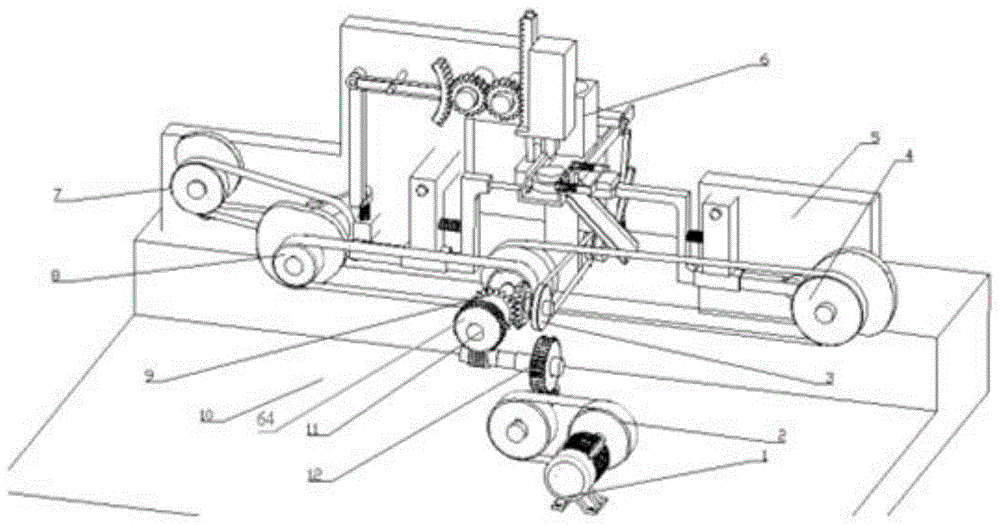
图1为本发明结构示意图;Fig. 1 is the structural representation of the present invention;
图2为本发明送料机构示意图Fig. 2 is the schematic diagram of the feeding mechanism of the present invention
图3为本发明定位机构示意图;3 is a schematic diagram of the positioning mechanism of the present invention;
图4为本发明夹紧机构示意图;4 is a schematic diagram of the clamping mechanism of the present invention;
图5为本发明钻孔机构示意图;5 is a schematic diagram of the drilling mechanism of the present invention;
图6为本发明出料机构示意图。FIG. 6 is a schematic diagram of the discharging mechanism of the present invention.
图中:1-电机、2-第一带轮传动系、3-第五带轮传动系、4-第四带轮传动系、5-夹紧机构挡板、6-料斗、7-第三带轮传动系、8-第二带轮传动系、9-锥齿轮传动系、10-底板、11-主轴、12-第一蜗轮蜗杆传动系、13-曲柄、14-送料摆杆底座、15-送料摆杆、16-曲柄连杆、17-支撑柱、18-滑块连杆、19-送料滑块、20-工作台、21-工件、22-出料滑道槽、23-出料滑道槽底板、24-挡板、25-定位凸轮、26-定位凸轮滚子、27-定位连杆、28-定位连杆支撑架、29-第一弹簧、30-定位机构内六角螺栓、31-定位杆、32-夹紧连杆、33-第二弹簧、34-夹紧连杆支撑架、35-夹紧凸轮、36-夹紧凸轮滚子、37-夹紧机构内六角螺栓、39-夹具、40-钻孔凸轮滚子、41-L型连杆、42-第三弹簧、43-钻孔摆杆、44-齿条定位杆、45-刀具、46-动力头、47-齿条、48-齿轮齿条机构、49-大齿廓、50-大齿廓连杆、51-钻孔凸轮、52-钻孔机构挡板、53-出料滑块、54-凵形连杆、55-导向柱、56-复位弹簧、57-出料连杆、58-出料摆杆、59-定位孔、60-曲柄轴、61-底板凸台、62-定位凸轮轴、63-夹紧凸轮轴、64-第二蜗轮蜗杆传动系、65-钻孔凸轮轴。In the figure: 1-motor, 2-first pulley drive train, 3-fifth pulley drive train, 4-fourth pulley drive train, 5-clamping mechanism baffle, 6-hopper, 7-third Pulley drive train, 8-second pulley drive train, 9-bevel gear drive train, 10-base plate, 11-spindle, 12-first worm gear drive train, 13-crank, 14-feeding swing rod base, 15- -Feeding swing rod, 16-crank connecting rod, 17-support column, 18-slider connecting rod, 19-feeding slider, 20-table, 21-workpiece, 22-discharge chute, 23-discharge Chute groove bottom plate, 24-baffle plate, 25-positioning cam, 26-positioning cam roller, 27-positioning connecting rod, 28-positioning connecting rod support frame, 29-first spring, 30-positioning mechanism socket head cap bolt, 31-Positioning rod, 32-Clamping connecting rod, 33-Second spring, 34-Clamping connecting rod support frame, 35-Clamping cam, 36-Clamping cam roller, 37-Clamping mechanism socket head cap bolt, 39-Clamp, 40-Drilling cam roller, 41-L-type connecting rod, 42-Third spring, 43-Drilling swing rod, 44-Rack positioning rod, 45-Tool, 46-Power head, 47- Rack, 48-gear and rack mechanism, 49-large tooth profile, 50-large tooth profile connecting rod, 51-drilling cam, 52-drilling mechanism baffle, 53-discharge slider, 54-shaped connection Rod, 55-guide column, 56-return spring, 57-discharge connecting rod, 58-discharge swing rod, 59-positioning hole, 60-crank shaft, 61-base plate boss, 62-positioning camshaft, 63- Clamping camshaft, 64-second worm gear train, 65-drilling camshaft.
具体实施方式Detailed ways
为了使本技术领域的人员更好地理解本申请中的技术方案,下面对本申请实施例中的技术方案进行清楚、完整地描述,显然,所描述的实施例仅仅是本申请一部分实施例,而不是全部的实施例。基于本申请中的实施例,本领域普通技术人员在没有做出创造性劳动前提下所获得的所有其他实施例,都应当属于本申请保护的范围。In order to make those skilled in the art better understand the technical solutions in the present application, the technical solutions in the embodiments of the present application will be described clearly and completely below. Obviously, the described embodiments are only a part of the embodiments of the present application, and Not all examples. Based on the embodiments in the present application, all other embodiments obtained by those of ordinary skill in the art without creative work shall fall within the scope of protection of the present application.
如图1所示,一种半自动钻床,包括底板10、送料机构、定位机构、夹紧机构、钻孔机构、出料机构和传动机构,所述底板10上固定有电机1和工作台20,所述送料机构为曲柄连杆机构,所述定位机构为凸轮连杆机构,且所述送料机构与定位机构配合实现定位,用于将工作台上待加工零件推送至钻孔工位,所述夹紧机构为凸轮连杆机构,将所述工作台上被推送至钻孔工位的待加工零件夹紧,所述钻孔机构对所述工作台钻孔工位上被夹紧的待加工零件进行钻孔加工,所述出料机构为平面七杆机构,将所述工作台钻孔工位上的已加工零件拉入出料滑道槽,所述传动机构包括带传动和齿轮传动,用于所述的送料机构、定位机构、夹紧机构、钻孔机构的传动连接。As shown in FIG. 1, a semi-automatic drilling machine includes a bottom plate 10, a feeding mechanism, a positioning mechanism, a clamping mechanism, a drilling mechanism, a discharging mechanism and a transmission mechanism, and a motor 1 and a worktable 20 are fixed on the bottom plate 10, The feeding mechanism is a crank connecting rod mechanism, the positioning mechanism is a cam connecting rod mechanism, and the feeding mechanism cooperates with the positioning mechanism to achieve positioning, and is used to push the parts to be processed on the worktable to the drilling station. The clamping mechanism is a cam linkage mechanism, which clamps the parts to be processed that are pushed to the drilling station on the worktable, and the drilling mechanism clamps the to-be-processed parts on the drilling station of the worktable. The parts are drilled, and the discharge mechanism is a plane seven-bar mechanism, which pulls the processed parts on the drilling station of the worktable into the discharge chute, and the transmission mechanism includes a belt drive and a gear drive. It is connected to the transmission of the feeding mechanism, the positioning mechanism, the clamping mechanism and the drilling mechanism.
优选地,如图1和2所示,所述送料机构包括曲柄13、送料摆杆底座14、送料摆杆15、曲柄连杆16、滑块连杆18、送料滑块19、曲柄轴60和底板凸台61,所述曲柄轴60固定安装在底板凸台60上,所述曲柄13安装在曲柄轴60上,且与所述曲柄轴60滚动配合连接,所述曲柄连杆16的一端连接所述曲柄13,另一端与所述送料摆杆15中部铰接,所述送料摆杆15一端与所述的送料摆杆底座14铰接,另一端与所述滑块连杆18的一端铰接,所述滑块连杆18的另一端与所述送料滑块19铰接,所述送料滑块19设置在工作台上,且沿工作台底面滑动,所述送料摆杆底座14固定在所述底板上,所述曲柄13旋转带动曲柄连杆16转动,曲柄连杆16拉动送料摆杆15摆动,从而带动滑块连杆18摆动,滑块连杆18推动送料滑块19沿所述的工作台20底面往复滑动,从而实现往复送料功能。Preferably, as shown in Figures 1 and 2, the feeding mechanism includes a
优选地,如图1和3所示,所述定位机构包括定位凸轮25、定位凸轮滚子26、定位连杆27、定位连杆支撑架28、定位机构内六角螺栓30、第一弹簧29、定位杆31和定位凸轮轴62,所述定位连杆27一端安装定位凸轮滚子26,且所述定位凸轮滚子26与所述定位凸轮25直接接触,所述定位凸轮轴62安装在钻孔机构挡板52侧面,与钻孔机构挡板52滚动配合连接,所述定位凸轮25安装在定位凸轮轴62上并与定位凸轮轴62传动配合连接,定位凸轮25在第二带轮传动系8的带动下旋转,从而带动定位凸轮滚子25转动,所述定位连杆27底部安装在定位连杆支撑架28下端的固定孔内,且沿所述定位连杆支撑架28下端的固定孔滑动,实现定位功能,所述定位连杆支撑架28上端通过定位机构内六角螺栓30固定在钻孔机构挡板52上,所述定位连杆27中部通过第一弹簧29与连杆支撑架28中部连接,所述的第一弹簧29在定位过程中被拉伸,所述的定位凸轮25回程时,所述的第一弹簧29拉动所述的定位连杆27,实现回位功能。所述的定位连杆27的上端与定位杆31一端固定连接,所述的定位杆31的另一端穿过工作台20钻孔工位侧面开设的定位孔59,且沿工作台的定位孔59往复运动,最终实现定位功能。Preferably, as shown in Figures 1 and 3, the positioning mechanism includes a
优选地,如图1和4所示,所述夹紧机构包括夹紧凸轮35、夹紧凸轮滚子36、第二弹簧33、夹紧连杆32、夹紧连杆支撑架34、夹紧机构内六角螺栓37、夹紧机构挡板5、夹具39和夹紧凸轮轴63,所述夹紧连杆32一端安装夹紧凸轮滚子36,所述夹紧凸轮滚子36与所述夹紧凸轮35直接接触,所述夹紧凸轮轴63安装在夹紧机构挡板5侧面并且与其滚动配合连接,所述夹紧凸轮35安装在夹紧凸轮轴63上并与其传动配合连接,所述夹紧凸轮35在第四带轮传动系4传动作用下旋转,从而带动夹紧凸轮滚子转动,所述夹紧连杆32底端安装在夹紧连杆支撑架34下端的固定孔内,且沿所述夹紧连杆支撑架34下端的固定孔滑动,实现定位功能;所述的夹紧连杆32中部通过第二弹簧33与夹紧连杆支撑架34中部连接,所述的第二弹簧33在夹紧过程中被拉伸,所述的夹紧凸轮35回程时,所述的第二弹簧33拉动所述的夹紧连杆32,实现回位功能;所述夹紧连杆32顶端与夹具39固定连接,所述夹具39底面与所述工作台底面共面,所述的夹紧连杆32推动夹具39沿工作台20底面移动,最终实现夹紧功能。Preferably, as shown in FIGS. 1 and 4 , the clamping mechanism includes a clamping
优选地,如图1和5所示,所述钻孔机构包括钻孔凸轮51、钻孔凸轮滚子40、L型连杆41、第三弹簧42、钻孔摆杆43、大齿廓连杆50、大齿廓49、齿轮齿条机构48、齿条定位杆44、动力头46、刀具45和钻孔凸轮轴65,所述L形连杆41一端安装钻孔凸轮滚子40,所述的钻孔凸轮滚子40与所述的钻孔凸轮51直接接触,所述钻孔凸轮轴65安装在钻孔机构挡板52侧面,且与钻孔机构挡板52滚动配合连接,所述钻孔凸轮51安装在钻孔凸轮轴65上并与钻孔凸轮轴65传动配合连接,所述钻孔凸轮51在第三带轮传动系7的传动作用下旋转,从而带动钻孔凸轮滚子转动,所述的L形连杆41中部的固定孔与钻孔机构挡板52上的转轴间隙配合,且钻孔凸轮51推动L形连杆41绕该转轴转动,所述L形连杆41另一端通过第三弹簧42与钻孔机构挡板52上的凸台连接,所述L形连杆41转动,使得第三弹簧42被拉伸,第三弹簧42的拉力使得钻孔凸轮滚子40始终与钻孔凸轮51相接触,所述钻孔摆杆43一端与所述L形连杆41连接第三弹簧42的一端铰接,所述钻孔摆杆43另一端与大齿廓连杆50的一端铰接,所述的大齿廓连杆50的另一端与大齿廓49连接,所述大齿廓连杆50中部的固定孔与钻孔机构挡板52上的转轴间隙配合,所述钻孔摆杆43带动大齿廓连杆50绕该转轴转动,所述齿轮齿条机构包括两个齿轮和一根齿条,且两个齿轮相互啮合,其中一个齿轮与大齿廓啮合连接,另一个齿轮与齿条啮合连接,所述两个齿轮与所述钻孔机构挡板52上的齿轮转轴间隙配合,防止在钻孔过程中所述的齿条47发生移动,影响钻孔精度;所述的齿条定位杆44一端固定在所述的钻孔机构挡板52的凸台上,另一端与所述齿条的固定孔间隙配合,且所述齿条沿齿条定位杆44上下移动,从而使得刀具45完成钻孔功能,所述动力头46与所述齿条焊接固定,所述的刀具安装在动力头46底部,且位于工作台钻孔加工工位上方。Preferably, as shown in Figures 1 and 5, the drilling mechanism includes a drilling cam 51, a
优选地,如图5和6所示,所述的出料机构为对称的七杆机构,包括凵形连杆54、两根出料摆杆58、两根出料连杆57、两个出料滑块53,两根复位弹簧56,所述的凵形连杆54固定在夹具39上,所述两根出料摆杆58分别对称铰接在凵形连杆54两端,所述两根出料连杆57的一端分别对称铰接在所述两根出料摆杆58的中部,所述两根出料连杆57另一端分别与一个出料滑块53铰接,所述凵形连杆54两侧内部各设有导向柱55,所述两根出料滑块53分别安装在导向柱55上,且沿所述导向柱滑动,所述两个复位弹簧56分别套接在两个导向柱上,且每个所述复位弹簧56两端分别连接出料滑块53和所述凵形连杆,当夹紧凸轮35进入推程时,工件21抵住所述的出料摆杆58进而使所述的出料摆杆58转动,所述的出料摆杆58带动所述的出料连杆57转动进而使所述的出料滑块53沿所述的导向柱55移动,所述的复位弹簧56在此过程中被压缩,当所述的夹紧机构到达指定的夹紧位置时,所述的复位弹簧56释放弹性势能,使得出料摆杆58回位,当所述的夹紧机构回位时,所述的出料摆杆58将已加工工件21拉入所述的出料滑道槽22,实现自动出料功能。Preferably, as shown in FIGS. 5 and 6 , the discharging mechanism is a symmetrical seven-bar mechanism, including a cam-shaped connecting
优选地,所述工作台20上设置了料斗6,所述的料斗通过内六角螺栓固定在钻孔机构挡板52上,所述工作台的钻孔工位上设置直径大于刀具直径的孔,并且其孔的中心线与刀具中心线重合,防止刀具45损伤工作台20台面,所述工作台的钻孔工位处的一侧设置了出料滑道槽22,其中,所述出料滑道槽22包括两块挡板24和出料滑道槽底板23,所述挡板24固定设置在出料滑道槽底板23两侧。Preferably, a hopper 6 is provided on the worktable 20, the hopper is fixed on the baffle plate 52 of the drilling mechanism by hexagon socket bolts, and a hole with a diameter larger than the diameter of the tool is set on the drilling station of the worktable, And the center line of the hole coincides with the center line of the tool to prevent the
优选地,所述电机1通过内六角螺栓固定在底板10上,所述的工作台20通过两根支撑柱17固定在底板10上。Preferably, the motor 1 is fixed on the base plate 10 through hexagon socket head bolts, and the worktable 20 is fixed on the base plate 10 through two support columns 17 .
优选地,所述的传动机构包括电机1、第一带轮传动系2、第二带轮传动系8、第三带轮传动系7、第四带轮传动系4、第五带轮传动系3、齿轮传动系和主轴11,所述齿轮传动系包括涡轮蜗杆传动系和锥齿轮传动系9,所述电机1经第一带轮传动系2与第一涡轮蜗杆传动系12传动连接,所述主轴11安装在第二涡轮蜗杆传动系64的涡轮上,所述第一蜗轮蜗杆传动系12与所述第二蜗轮蜗杆传动系64传动连接,所述主轴11通过第二带轮传动系8与所述定位机构的定位凸轮25传动连接,所述定位机构的凸轮25通过第三带轮传动系7与钻孔机构的钻孔凸轮51传动连接,所述主轴11通过第四带轮传动系4与夹紧机构的夹紧凸轮35传动连接,所述主轴11由锥齿轮传动系9换向后通过第五带轮传动系3与所述送料机构传动连接。Preferably, the transmission mechanism includes a motor 1, a first pulley drive train 2, a second pulley drive train 8, a third pulley drive train 7, a fourth pulley drive train 4, and a fifth pulley drive train 3. Gear train and main shaft 11, the gear train includes a worm gear train and a bevel gear train 9, the motor 1 is connected to the first worm gear train 12 via the first pulley train 2, so The main shaft 11 is mounted on the turbine of the second worm gear train 64, the first worm gear train 12 is drivingly connected with the second worm gear train 64, and the main shaft 11 passes through the second pulley drive train 8. It is drivingly connected with the
优选地,所述夹紧连杆为“Z”型结构。Preferably, the clamping link has a "Z" type structure.
本发明的工作原理如下:The working principle of the present invention is as follows:
当需要进行零件加工时,将待加工件向料斗中投入到工作台上,随后开启电机,由电机经过第一带轮传动系2和第一涡轮蜗杆传动系12带动安装在第二涡轮蜗杆传动系64的涡轮上的主轴11转动;随后主轴11由锥齿轮传动系9换向后通过第五带轮传动系3带动送料机构中的曲柄13旋转,从而能带动与曲柄连接的曲柄连杆16转动,从而拉动送料摆杆15摆动,由送料摆杆15带动滑块连杆18摆动,从而带动与滑块连杆18铰接的送料滑块19推动工作台上的待加工零件21沿着工作台底面到钻孔工位,从而实现送料功能;When the parts need to be processed, put the parts to be processed into the hopper and put them on the workbench, then turn on the motor, which is driven by the motor through the first pulley drive train 2 and the first turbine worm drive train 12 to be installed on the second turbine worm drive The main shaft 11 on the turbine of the system 64 rotates; then the main shaft 11 is reversed by the bevel gear transmission 9 and drives the
当送料滑块19将待加工零件21推送到钻孔加工工位的同时,主轴11通过第二带轮传动系8带动定位机构的定位凸轮25转动,定位凸轮25通过定位凸轮滚子26推动定位连杆27沿着定位连杆支撑架28的固定孔移动,从而推动连接在定位连杆27端部的定位杆31沿着工作台20上开设的定位孔59移动,从而实现定位功能,使得送料滑块19能将待加工零件21准确推送到工作台的钻孔加工工位上。与此同时,在定位过程中,设置在定位连杆支撑架28和定位连杆27之间的第一弹簧29被拉伸,定位凸轮25回程时,第一弹簧29拉动定位连杆27,实现回位功能。When the feeding slider 19 pushes the to-be-processed part 21 to the drilling station, the main shaft 11 drives the
当待加工零件21被准确推送至钻孔加工工位后,送料机构立刻回程,主轴11通过第四带轮传动系4带动夹紧机构的夹紧凸轮35转动,夹紧凸轮35通过夹紧凸轮滚子36推动夹紧连杆32沿夹紧连杆支撑架34的固定孔移动,与夹紧连杆32顶端固定连接的夹具39在夹紧连杆32的推动下沿工作台底面移动,夹紧凸轮35到达远休止时待加工工件21被夹紧,并依靠凸轮的保压特性实现持续夹紧,与此同时,在夹紧过程中,设置在夹紧连杆中部与夹紧连杆支撑架之间的第二弹簧被拉伸,当夹紧凸轮35回程时,第二弹簧33拉动夹紧连杆32,实现回位功能。When the part 21 to be processed is accurately pushed to the drilling station, the feeding mechanism immediately returns, and the main shaft 11 drives the clamping
当夹具39到达指定位置后,定位凸轮25通过第三带轮传动系7带动钻孔机构的钻孔凸轮51转动,L形连杆41中部固定孔与所述的钻孔机构挡板52上的转轴间隙配合,钻孔凸轮51通过钻孔凸轮滚子推动L形连杆41绕钻孔机构挡板52上的转轴转动, 由L形连杆41带动钻孔摆杆43转动,从而带动大齿廓连杆50绕钻孔机构挡板52上的转轴转动,设置在大齿廓连杆50一端的大齿廓49与齿轮齿条机构48啮合传动,并由齿轮齿条机构48带动焊接在齿条47上的动力头46上下运动,设置在动力头46底部的刀具45随之上下运动,从而使得刀具45完成钻孔功能。此外, L形连杆41一端与钻孔机构挡板52凸台之间连接的第三弹簧42在L形连杆41转动的过程中被拉伸,第三弹簧42的拉力使得钻孔凸轮滚子40始终与所述的钻孔凸轮51相接触,齿条定位杆44与齿条47内部固定孔间隙配合,用于防止在钻孔过程中所述的齿条47发生移动,影响钻孔精度。When the
当待加工零件加工完成后,钻孔机构率先回位,随后定位机构回位,最后夹紧机构回位,出料机构利用夹紧机构回位进行出料,当夹紧凸轮35进入推程即夹具39逐渐靠近待加工工件21的过程中,待加工零件21抵住出料摆杆58进而使出料摆杆58转动,由出料摆杆58带动出料连杆57转动进而使出料滑块53沿导向柱55移动,套接在导向柱上的复位弹簧56在此过程中被压缩,当所述的夹紧机构夹紧工件(夹紧凸轮35到达远休止)时,所述的复位弹簧56释放弹性势能,使得出料摆杆58回位,当夹紧机构回位时,所述的出料摆杆58将已加工工件21拉入出料滑道槽22,实现自动出料功能。When the processing of the part to be processed is completed, the drilling mechanism returns first, then the positioning mechanism returns, and finally the clamping mechanism returns, and the discharging mechanism uses the clamping mechanism to return to the position to discharge the material. When the clamping
本发明中,各个机构都是通过各凸轮、凸轮轴以及轴杆的配合设计实现各机构按顺序工作,属于常规技术手段,本领域技术人员可根据说明书中各机构的工作顺序对各机构的凸轮、凸轮轴以及轴杆进行设计,从而实现各机构按顺序工作。本发明中除第一带轮传动系外,其余全部带轮传动系全部使用同步带。In the present invention, each mechanism is designed to work in sequence through the cooperation design of each cam, camshaft and shaft, which belongs to a conventional technical means. Those skilled in the art can adjust the cam of each mechanism according to the working order of each mechanism in the description. , camshaft and shaft are designed so that each mechanism can work in sequence. In the present invention, except for the first pulley drive train, all the other pulley drive trains use synchronous belts.
对所公开的实施例的上述说明,使本领域专业技术人员能够实现或使用本发明。对这些实施例的两种修改对本领域的专业技术人员来说将是显而易见的,本文中所定义的一般原理可以在不脱离本发明的精神或范围的情况下,在其它实施例中实现。因此,本发明将不会被限制于本文所示的这些实施例,而是要符合与本文所公开的原理和新颖特点相一致的最宽的范围 。The above description of the disclosed embodiments enables any person skilled in the art to make or use the present invention. Both modifications to these embodiments will be readily apparent to those skilled in the art, and the generic principles defined herein may be implemented in other embodiments without departing from the spirit or scope of the invention. Thus, the present invention is not intended to be limited to the embodiments shown herein, but is to be accorded the widest scope consistent with the principles and novel features disclosed herein.
Claims (9)
Priority Applications (1)
| Application Number | Priority Date | Filing Date | Title |
|---|---|---|---|
| CN201810290554.8A CN108284347B (en) | 2018-04-03 | 2018-04-03 | Semi-automatic drilling machine |
Applications Claiming Priority (1)
| Application Number | Priority Date | Filing Date | Title |
|---|---|---|---|
| CN201810290554.8A CN108284347B (en) | 2018-04-03 | 2018-04-03 | Semi-automatic drilling machine |
Publications (2)
| Publication Number | Publication Date |
|---|---|
| CN108284347A CN108284347A (en) | 2018-07-17 |
| CN108284347B true CN108284347B (en) | 2020-03-17 |
Family
ID=62834020
Family Applications (1)
| Application Number | Title | Priority Date | Filing Date |
|---|---|---|---|
| CN201810290554.8A Expired - Fee Related CN108284347B (en) | 2018-04-03 | 2018-04-03 | Semi-automatic drilling machine |
Country Status (1)
| Country | Link |
|---|---|
| CN (1) | CN108284347B (en) |
Families Citing this family (15)
| Publication number | Priority date | Publication date | Assignee | Title |
|---|---|---|---|---|
| CN108890042A (en) * | 2018-08-29 | 2018-11-27 | 常熟希那基汽车零件有限公司 | A kind of cam-type high speed front end processing machine |
| CN109333674B (en) * | 2018-11-23 | 2023-06-02 | 广西科技大学 | Profiling device for wooden clothes hanger |
| CN109407468A (en) * | 2018-12-11 | 2019-03-01 | 江苏友迪电气有限公司 | A kind of aluminium plate head fixing device of platemaking machine |
| CN111408653A (en) * | 2020-03-26 | 2020-07-14 | 龙岩市腾兴机械维修有限公司 | High-efficient punching device is used in machine parts processing |
| CN111546296A (en) * | 2020-05-28 | 2020-08-18 | 江苏安全技术职业学院 | Mechanical intermittent control device and workbench based on mechanical intermittent control device |
| CN112077200A (en) * | 2020-08-07 | 2020-12-15 | 李琴 | Punching equipment for punching steel plate |
| CN112959138B (en) * | 2021-01-22 | 2022-12-16 | 南通天幕精密机械有限公司 | Fixed periodic is in coordination with cutting device |
| CN114192900B (en) * | 2021-12-16 | 2023-09-22 | 深圳中壹建设(集团)有限公司 | Bolt tooth opening device for building decoration |
| CN114570843A (en) * | 2022-03-23 | 2022-06-03 | 浙江新奥兰汽车空调有限公司 | Automatic pipe expanding machine |
| CN114714447B (en) * | 2022-05-11 | 2023-03-28 | 九江金鹰科技有限公司 | Side hole machine of multi-axis motion control system |
| CN115251537A (en) * | 2022-08-30 | 2022-11-01 | 浙江青田卡洛斯鞋业有限公司 | Pushing mechanism of vamp drilling equipment |
| CN115504261B (en) * | 2022-10-21 | 2025-10-24 | 青岛海纳瑞克智能装备有限公司 | An egg packaging and egg tray disassembly machine |
| CN117300516B (en) * | 2023-10-26 | 2024-02-02 | 山东金泰高温材料有限公司 | Tapping equipment for hard press-in repair of blast furnace lining and lining repair method |
| CN118700235B (en) * | 2024-08-28 | 2025-01-03 | 四川帕沃可矿物纤维制品集团有限公司 | A preparation system for short-section basalt fiber composite material |
| CN119681678B (en) * | 2025-01-10 | 2026-07-24 | 霍山嘉远智能制造有限公司 | A vibration damping fixture for machining extended thin-walled, heavy-duty valve covers on a horizontal CNC lathe |
Family Cites Families (7)
| Publication number | Priority date | Publication date | Assignee | Title |
|---|---|---|---|---|
| JP2010259348A (en) * | 2009-04-30 | 2010-11-18 | Mutsu Kaden Tokki:Kk | Automatic scallop feeding method to scallop drilling machine, scallop automatic feeding device to scallop drilling machine, and scallop drilling device with scallop automatic feeding device |
| CN202387872U (en) * | 2011-12-28 | 2012-08-22 | 宁波荣智自动化科技有限公司 | High-precision reciprocating feeding mechanism |
| CN103567804A (en) * | 2013-11-07 | 2014-02-12 | 重庆风过旗扬科技发展有限公司 | Automatic feeding device of drilling machine |
| CN104858477A (en) * | 2015-04-10 | 2015-08-26 | 河海大学常州校区 | Semi-automatic drilling machine |
| CN105750983A (en) * | 2016-05-06 | 2016-07-13 | 河海大学常州校区 | Automatic drilling machine |
| CN105750985A (en) * | 2016-05-13 | 2016-07-13 | 河海大学常州校区 | Semi-automatic drilling machine |
| CN107716986A (en) * | 2017-11-07 | 2018-02-23 | 河海大学常州校区 | A kind of semi-automatic drilling machine |
-
2018
- 2018-04-03 CN CN201810290554.8A patent/CN108284347B/en not_active Expired - Fee Related
Also Published As
| Publication number | Publication date |
|---|---|
| CN108284347A (en) | 2018-07-17 |
Similar Documents
| Publication | Publication Date | Title |
|---|---|---|
| CN108284347A (en) | A kind of semi-automatic drilling machine | |
| CN110757169B (en) | A cutting and grinding integrated device for aluminum alloy processing and using method thereof | |
| CN207840923U (en) | Oil Pump rotor burr remover | |
| CN221564812U (en) | Main shaft clamping and feeding mechanism for vibration exciter assembly line | |
| CN217201852U (en) | A Portable Belt Lifting Device for Belt Conveyor Idler Roller Replacement | |
| CN113714659B (en) | Femtosecond laser cutting device for SMT template | |
| CN112518336A (en) | Machining device convenient to clamp and used for lighting lamp fixing piece | |
| CN219152180U (en) | Cylinder bottom machining device for hydraulic cylinder welding part | |
| CN217166644U (en) | Planer type milling machine | |
| CN116252213A (en) | A grinding device and mechanical parts processing equipment | |
| CN211840649U (en) | Laser punching device for hardware machining | |
| CN221773588U (en) | A cutting device for machining a rotary kiln support wheel shaft | |
| CN221135676U (en) | A clamping fixture for production and processing of hydraulic cylinders | |
| CN210550077U (en) | Cylinder cap deburring complete machine | |
| CN222359570U (en) | Conveyor frame welding device | |
| CN223334853U (en) | A PCB processing anti-deformation fixing device | |
| CN220222282U (en) | Material feeding unit is used in aluminium alloy processing | |
| CN211053144U (en) | A face milling machine for machining of crystal growth furnace frame | |
| CN221247185U (en) | A portable steel plate chamfering machine for steel plate processing | |
| CN222520256U (en) | Laser drilling device for battery base material | |
| CN220902303U (en) | Welding device for aluminum nitride copper-clad substrate and chip | |
| CN222098090U (en) | A vacuum packaging device for the production and processing of mustard tuber | |
| CN218253902U (en) | Milling machine workpiece support frame | |
| CN219831310U (en) | Chip testing device | |
| CN221603910U (en) | Battery tray inner frame processing tilting mechanism |
Legal Events
| Date | Code | Title | Description |
|---|---|---|---|
| PB01 | Publication | ||
| PB01 | Publication | ||
| SE01 | Entry into force of request for substantive examination | ||
| SE01 | Entry into force of request for substantive examination | ||
| GR01 | Patent grant | ||
| GR01 | Patent grant | ||
| CF01 | Termination of patent right due to non-payment of annual fee |
Granted publication date: 20200317 |
|
| CF01 | Termination of patent right due to non-payment of annual fee |