CN108196642B - Computer box with light sensation effect - Google Patents
Computer box with light sensation effect Download PDFInfo
- Publication number
- CN108196642B CN108196642B CN201810221089.2A CN201810221089A CN108196642B CN 108196642 B CN108196642 B CN 108196642B CN 201810221089 A CN201810221089 A CN 201810221089A CN 108196642 B CN108196642 B CN 108196642B
- Authority
- CN
- China
- Prior art keywords
- machine body
- top cover
- rear end
- base
- end base
- Prior art date
- Legal status (The legal status is an assumption and is not a legal conclusion. Google has not performed a legal analysis and makes no representation as to the accuracy of the status listed.)
- Active
Links
Images




Classifications
-
- G—PHYSICS
- G06—COMPUTING OR CALCULATING; COUNTING
- G06F—ELECTRIC DIGITAL DATA PROCESSING
- G06F1/00—Details not covered by groups G06F3/00 - G06F13/00 and G06F21/00
- G06F1/16—Constructional details or arrangements
- G06F1/18—Packaging or power distribution
- G06F1/183—Internal mounting support structures, e.g. for supporting printed circuit boards
-
- G—PHYSICS
- G06—COMPUTING OR CALCULATING; COUNTING
- G06F—ELECTRIC DIGITAL DATA PROCESSING
- G06F1/00—Details not covered by groups G06F3/00 - G06F13/00 and G06F21/00
- G06F1/16—Constructional details or arrangements
- G06F1/20—Cooling means
-
- G—PHYSICS
- G06—COMPUTING OR CALCULATING; COUNTING
- G06F—ELECTRIC DIGITAL DATA PROCESSING
- G06F2200/00—Indexing scheme relating to G06F1/04 - G06F1/32
- G06F2200/20—Indexing scheme relating to G06F1/20
- G06F2200/201—Cooling arrangements using cooling fluid
Landscapes
- Engineering & Computer Science (AREA)
- Theoretical Computer Science (AREA)
- Human Computer Interaction (AREA)
- Physics & Mathematics (AREA)
- General Engineering & Computer Science (AREA)
- General Physics & Mathematics (AREA)
- Computer Hardware Design (AREA)
- Power Engineering (AREA)
- Cooling Or The Like Of Electrical Apparatus (AREA)
Abstract
The invention discloses a computer box with a light sensing effect, which comprises a machine body, a front end top cover, an inductor, a rear end top cover, a water pump and a tank body, wherein the bottom end of the machine body is connected with a front end base, a sliding block is arranged on the outer side of the top end of the machine body, a groove is arranged on the inner side of the sliding block, a support lug is distributed at the left end of the sliding block, a bolt is fixed at the left end of the support lug, the front end top cover is embedded at the upper end of the support lug, a buckle is arranged on the inner side of the bottom end of the front end top cover, a dust screen is connected to the lower end of the inner side of the machine body, a clamping groove is arranged at the top end of the inner side of the dust screen, a USB. This computer box with light sense effect sets up the organism, is splayed column structure between front end base and the rear end base to be same level column structure between front end base and the rear end base, front end base and rear end base play fine fixed action.
Description
Technical Field
The invention relates to the technical field of computer boxes, in particular to a computer box with a light sensation effect.
Background
The fully closed water cooled computer casing is one heat dissipating device for the heat generating parts inside the computer. The circulating liquid is used for storing circulating liquid, the heat of a CPU (central processing unit) is released by the circulating liquid flowing back, the low-temperature circulating liquid flows into the pipeline again, the circulating liquid transmits the heat to the radiating fins with the ultra-large surface area, and the fans on the radiating fins take away the heat of the flowing air.
Computer box in use on the market appears quick-witted case switch and needs manual pressing, uses for a long time and probably leads to the shell fragment in the button to appear damaging, the unable normal use of user, and the computer box does not have fine waterproof construction simultaneously, prevents that in use from appearing in the water drop box, leads to the internal circuit short circuit to appear, brings the trouble for the user, for this reason, we propose a computer box with light sense effect.
Disclosure of Invention
The invention aims to provide a computer box body with a light sensation effect, and aims to solve the problems that a chassis switch of a computer box body in the market proposed in the background art needs to be manually pressed in use, a spring plate in a button is possibly damaged due to long-time use, a user cannot normally use the computer box body, and meanwhile the computer box body does not have a good waterproof structure, so that the problem that water falls into the computer box body in use, an internal circuit is short-circuited, and troubles are brought to the user is solved.
In order to achieve the purpose, the invention provides the following technical scheme: a computer box with light sensing effect comprises a machine body, a front end top cover, an inductor, a rear end top cover, a water pump and a tank body, wherein the bottom end of the machine body is connected with a front end base, a sliding block is installed on the outer side of the top end of the machine body, a groove is installed on the inner side of the sliding block, supporting lugs are distributed at the left end of the sliding block, a bolt is fixed at the left end of each supporting lug, the front end top cover is embedded at the upper end of each supporting lug, a buckle is arranged on the inner side of the bottom end of the front end top cover, a dust screen is connected to the lower end of the inner side of the machine body, a clamping groove is installed at the top end of the inner side of the dust screen, a USB (universal serial bus) jack is embedded at the upper end of the right side of the dust screen, an on-off button is arranged at the upper end of the USB jack, an indicating lamp is, the utility model discloses a water pump, including the organism, the right side of organism, the bottom of rear end base is provided with the slipmat, the right side of mounting panel distributes and has dustproof blade, and the inboard of dustproof blade is connected with the fan, the left side internally mounted of organism has the fixed plate, the water pump is fixed in the inboard of fixed plate, and the lower extreme of water pump inlays and have the pressurized chamber, the jar body sets up in the lower extreme of pressurized chamber, the inboard distribution of the jar body has the coolant liquid, and the bottom inboard of the jar body runs through there is a jar mouth, the outside of jar mouth is connected with the screw plug, the outlet valve is installed on the bottom right side of the jar body, and the right side of outlet valve is fixed with the clamp tongue piece, the bottom of clamp tongue piece is inlayed and is had the screw, the right side of clamp tongue piece distributes and has.
Preferably, the machine body, the front end base and the rear end base are of an integrated structure, a splayed structure is formed between the front end base and the rear end base, and a same horizontal structure is formed between the front end base and the rear end base.
Preferably, the support lug is movably connected with the machine body, the support lug is in threaded connection with the bolt, and the support lug is symmetrically distributed along the central axis of the machine body.
Preferably, the front end top cover is of an arc-shaped structure, the arc angle of the front end top cover is matched with the front groove of the machine body, and the coverage area of the front end top cover is the same as the front upper end of the machine body.
Preferably, the front end of the rear end top cover is of an inwards concave structure, and a combined matching structure is formed between the rear end top cover and the front end top cover.
Preferably, the dustproof blades are uniformly distributed on the outer side of the fan at equal intervals, and the number of the fans is 3.
Preferably, the fixing plate is of a U-shaped structure, and the fixing plate and the machine body are welded.
Preferably, the circumference of the threaded plug is the same as that of the tank opening, the threaded plug and the tank opening are mutually attached, and a detachable structure is arranged between the threaded plug and the tank opening.
Preferably, the hose is connected with the water outlet valve through a clamping tongue piece, and the clamping tongue piece is in threaded connection with the screw.
Compared with the prior art, the invention has the beneficial effects that: the computer case with the light sensation effect is provided with a case body, a splayed structure is formed between a front end base and a rear end base, the front end base and the rear end base are in the same horizontal structure, the front end base and the rear end base have good fixing effects, the front end base and the rear end base are prevented from being unstably fixed in use, the case that internal parts of the case body are damaged due to the inclined collapse of the case body is avoided, the case that the internal parts of the case body are damaged due to the horizontal placement of the case body is ensured, the case body is prevented from being placed in a non-horizontal state for a long time, the internal parts are prevented from deviating, the service life of the case body is shortened, a fixing plate is arranged inside the left side of the case body, the fixing plate is in a U-shaped structure, the fixing plate and the case body are welded, the fixing plate can firmly fix and clamp a water pump and a tank body, the water pump is prevented from falling off, the front end top cover is embedded at the upper end of the support lug, the front end top cover is of an arc-shaped structure, the arc angle of the front end top cover is matched with the front groove of the machine body, the front end top cover plays a good role in protection, a user can turn the front end top cover downwards under the condition of not using the machine body, so that the front section of the front side of the machine body is covered by the front end top cover, dust is prevented from entering the interior of the part from the opening of the part, the service life of the part is shortened, meanwhile, when the user uses the device, the front end top cover can play a waterproof role to prevent the water from falling into the machine body in use to cause the short circuit of the internal circuit, the inductor is fixed in the left side upper end of dust screen, and the user can be through placing the anterior segment of inductor with the hand, and the inductor receives the signal, opens the computer, and the user need not the manual button of pressing and just can open the computer.
Drawings
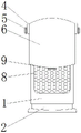
FIG. 1 is a schematic view of a computer case with light sensation effect according to the present invention;
FIG. 2 is a schematic view of a structure of the computer case with light sensation effect according to the present invention, wherein the top cover at the front end of the computer case is folded inwards;
FIG. 3 is a schematic diagram of a right side structure of a computer case with light sensation effect according to the present invention;
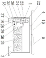
FIG. 4 is a schematic diagram of the left side internal structure of a computer case with light sensation effect according to the present invention;
FIG. 5 is a schematic view of a partially enlarged structure of a water outlet valve of a computer case with light sensation effect according to the present invention;
FIG. 6 is a schematic view of a fixing plate structure of a computer case with light sensation effect according to the present invention.
In the figure: 1. the automobile lamp comprises a machine body, 2, a front end base, 3, a sliding block, 4, a support lug, 5, a bolt, 6, a front end top cover, 7, a buckle, 8, a dustproof net, 9, a clamping groove, 10, a USB jack, 11, a sensor, 12, a switch button, 13, an indicator light, 14, a CD-ROM, 15, a groove, 16, a rear end top cover, 17, a mounting plate, 18, a rear end base, 19, an anti-slip pad, 20, a dustproof blade, 21, a fan, 22, a fixing plate, 23, a water pump, 24, a pressurizing chamber, 25, a tank body, 26, cooling liquid, 27, a tank opening, 28, a threaded plug, 29, a water outlet valve, 30, a hose, 31, a clamping tongue piece, 32, a screw, 33 and a waterproof ring.
Detailed Description
The technical solutions in the embodiments of the present invention will be clearly and completely described below with reference to the drawings in the embodiments of the present invention, and it is obvious that the described embodiments are only a part of the embodiments of the present invention, and not all of the embodiments. All other embodiments, which can be derived by a person skilled in the art from the embodiments given herein without making any creative effort, shall fall within the protection scope of the present invention.
Referring to fig. 1-6, the present invention provides a technical solution: a computer case with light sensation effect comprises a machine body 1, a front end base 2, a sliding block 3, a support lug 4, a bolt 5, a front end top cover 6, a buckle 7, a dust screen 8, a clamping groove 9, a USB jack 10, an inductor 11, a switch button 12, an indicator light 13, a CD-ROM 14, a groove 15, a rear end top cover 16, a mounting plate 17, a rear end base 18, an anti-slip pad 19, a dust-proof blade 20, a fan 21, a fixing plate 22, a water pump 23, a pressurizing chamber 24, a tank body 25, cooling liquid 26, a tank opening 27, a threaded plug 28, a water outlet valve 29, a hose 30, a clamping tongue piece 31, a screw 32 and a waterproof ring 33, wherein the bottom end of the machine body 1 is connected with the front end base 2, the sliding block 3 is arranged on the outer side of the top end of the machine body 1, the front end base 2 and the rear end base 18 are of an integrated structure, the front end base 2 and the rear end base 18 are of a splayed structure, and the front end base 2 and the rear end base, the front end base 2 and the rear end base 18 play a good role in fixing, so that the situation that the front end base 2 and the rear end base 18 are unstable to cause the machine body 1 to incline and collapse and the internal parts of the machine body 1 are possibly damaged in use is prevented, the machine body 1 is ensured to be placed in a horizontal state, the machine body 1 is prevented from being placed in a non-horizontal state for a long time and possibly causing the internal parts to deviate, the service life of the machine body 1 is shortened, the inner side of the sliding block 3 is provided with the groove 15, the left end of the sliding block 3 is provided with the support lug 4, the left end of the support lug 4 is fixedly provided with the bolt 5, the support lug 4 is movably connected with the machine body 1, the support lug 4 is in threaded connection with the bolt 5, the support lug 4 is symmetrically distributed along the central axis of the machine body 1, a user can turn over the support lug 4 inwards or outwards according to own needs, and the user can adjust the inwards clamping force of the support lug 4, the front end top cover 6 is embedded at the upper end of the support lug 4, a buckle 7 is arranged at the inner side of the bottom end of the front end top cover 6, the front end top cover 6 is of an arc-shaped structure, the arc angle of the front end top cover 6 is matched with the front groove of the machine body 1, the coverage area of the front end top cover 6 is the same as the front upper end of the machine body 1, the front end top cover 6 plays a good role in protection, a user can turn over the front end top cover 6 downwards under the condition of not using, so that the front end top cover 6 covers the front section of the machine body 1, dust is prevented from entering the interior of a part from an opening of the part, the service life of the part is shortened, meanwhile, the front end top cover 6 can play a waterproof role when the user is using, water is prevented from falling into the machine body 1 in use, the condition that a short circuit occurs in the machine body, certain economic loss is brought to the user, a clamping groove 9 is arranged at the top end of the inner side of the dustproof net 8, a USB jack 10 is embedded at the upper end of the right side of the dustproof net 8, an inductor 11 is fixed at the upper end of the left side of the dustproof net 8, a switch button 12 is arranged at the upper end of the USB jack 10, indicator lights 13 are distributed at the upper end of the switch button 12, an optical drive 14 is connected at the top end of the inner side of the machine body 1, a rear end top cover 16 is arranged at the tail end of a front end top cover 6, the front end of the rear end top cover 16 is of an inwards concave structure, a combinable and matched structure is formed between the rear end top cover 16 and the front end top cover 6, a user can assemble the rear end top cover 16 and the front end top cover 6 into a complete top cover by installing the rear end top cover 16 and the front end top cover 6, the situation that the top cover cannot play a good waterproof protection role due to the occurrence of a large gap between the rear end top, the bottom end of the rear end base 18 is provided with a non-slip mat 19, the right side of the mounting plate 17 is distributed with dustproof blades 20, the inner side of each dustproof blade 20 is connected with a fan 21, the dustproof blades 20 are uniformly distributed on the outer side of the fan 21 at equal intervals, 3 fans 21 are arranged, the dustproof blades 20 play a good dustproof role, the fan 21 is prevented from being wound by some objects such as connecting ropes in use, the fan 21 is damaged, a fixing plate 22 is arranged inside the left side of the machine body 1, the fixing plate 22 is in a U-shaped structure, the fixing plate 22 is welded with the machine body 1, the fixing plate 22 can firmly fix and clamp the water pump 23 and the tank body 25, the water pump 23 is prevented from falling off from the fixing plate 22 in work, cooling liquid 26 flows out from a gap between the water pump 23 and the pressurizing chamber 24, the water pump 23 is fixed on the inner side of the fixing plate 22, the tank body 25 is arranged at the lower end of the pressurization chamber 24, the cooling liquid 26 is distributed on the inner side of the tank body 25, the tank opening 27 penetrates through the inner side of the bottom end of the tank body 25, the outer side of the tank opening 27 is connected with the threaded plug 28, the circumference of the threaded plug 28 is the same as that of the tank opening 27, the threaded plug 28 and the tank opening 27 are mutually attached, and a detachable structure is arranged between the threaded plug 28 and the tank opening 27, when a user cannot absorb heat of the cooling liquid 26 due to the fact that the cooling liquid 26 in the tank body 25 is used for a long time, the user can open the tank opening 27 by continuously rotating the threaded plug 28 to suck out the cooling liquid 26 in the tank body 25 and replace the new cooling liquid 26, the use of the user is facilitated, the water outlet valve 29 is arranged on the right side of the bottom end of the tank body 25, the clamping tongue piece 31 is fixed on the right side of the water outlet valve 29, the, and the right side of the waterproof ring 33 is provided with a hose 30, the hose 30 is connected with the water outlet valve 29 through a clamping tongue piece 31, the clamping tongue piece 31 is in threaded connection with a screw 32, and when the hose 30 is loosened from the water outlet valve 29, a user can tighten the screw 32 to retract the clamping tongue piece 31 inwards to reduce the gap between the hose 30 and the water outlet valve 29.
The working principle of the embodiment is as follows: for the computer case with the light sensation effect, firstly, a hand is placed at the front section of the inductor 11, the inductor 11 receives a signal, the model of the inductor 11 is DLR-1170, the machine body 1 is opened, at the moment, the machine body 1 starts to work, heat is generated inside the machine body 1, the bottom end of the machine body 1 is connected with the front end base 2, the front end base 2 and the rear end base 18 are in a splayed structure, the front end base 2 and the rear end base 18 play a good fixing role to prevent the front end base 2 and the rear end base 18 from being unstably fixed in use to cause the machine body 1 to incline and collapse, at the moment, the water pump 23 starts to work, the pressurizing chamber 24 pressurizes and transmits the cooling liquid 26 in the tank 25, so that the cooling liquid 26 flows into a pipeline in the fan 21 through the hose 30 and flows into the hose 30 on the right side of the bottom end of the tank 25 from the pipeline in the fan 21 to perform circulating reciprocating motion, the right side of the waterproof ring 33 is provided with a hose 30, the hose 30 is connected with the water outlet valve 29 through a clamping tongue piece 31, the clamping tongue piece 31 is in threaded connection with a screw 32, when the hose 30 is loosened from the water outlet valve 29, a user can screw the screw 32 to shrink the clamping tongue piece 31 inwards to reduce a gap between the hose 30 and the water outlet valve 29, the cooling liquid absorbs heat generated inside the machine body 1, so that the temperature inside the machine body 1 is reduced, finally, when the user does not need to use the computer, the user closes the computer, the left end of the sliding block 3 is provided with a support lug 4, the support lug 4 is movably connected with the machine body 1, the support lug 4 is in threaded connection with the bolt 5, the user can turn over the front end top cover 6 downwards according to own requirements, so that the front end top cover 6 covers the front section of the machine body 1, and dust is prevented from entering the part from the opening of the part, this is the working principle of the computer case with light sensation effect.
Although embodiments of the present invention have been shown and described, it will be appreciated by those skilled in the art that changes, modifications, substitutions and alterations can be made in these embodiments without departing from the principles and spirit of the invention, the scope of which is defined in the appended claims and their equivalents.
Claims (5)
1. The utility model provides a computer box with light sense effect, includes organism (1), front end top cap (6), inductor (11), rear end top cap (16), water pump (23) and jar body (25), its characterized in that: the bottom of the machine body (1) is connected with a front end base (2), a sliding block (3) is installed on the outer side of the top end of the machine body (1), a groove (15) is installed on the inner side of the sliding block (3), supporting lugs (4) are distributed at the left end of the sliding block (3), a bolt (5) is fixed at the left end of each supporting lug (4), a front end top cover (6) is inlaid at the upper end of each supporting lug (4), a buckle (7) is arranged on the inner side of the bottom end of each front end top cover (6), a dust screen (8) is connected to the lower end of the inner side of the machine body (1), a clamping groove (9) is installed at the top end of the inner side of the dust screen (8), a USB jack (10) is inlaid at the upper end of the right side of the dust screen (8), the sensor (11) is fixed at the upper end of the left side of the dust screen (8), and the, opening the machine body (1); the USB flash disk is characterized in that a switch button (12) is arranged at the upper end of the USB jack (10), indicator lamps (13) are distributed at the upper end of the switch button (12), a CD-ROM (14) is connected to the top end of the inner side of the machine body (1), a rear end top cover (16) is installed at the tail end of a front end top cover (6), an installation plate (17) is fixed inside the right side of the machine body (1), a rear end base (18) is embedded in the left side of the bottom end of the machine body (1), an anti-slip pad (19) is arranged at the bottom end of the rear end base (18), dustproof blades (20) are distributed on the right side of the installation plate (17), a fan (21) is connected to the inner side of the dustproof blades (20), a fixed plate (22) is installed inside the left side of the machine body (1), a water pump (23) is fixed on the inner side of the fixed plate (22), a pressurizing chamber, the cooling liquid (26) is distributed on the inner side of the tank body (25), a tank opening (27) penetrates through the inner side of the bottom end of the tank body (25), the outer side of the tank opening (27) is connected with a threaded plug (28), a water outlet valve (29) is installed on the right side of the bottom end of the tank body (25), a clamping tongue piece (31) is fixed on the right side of the water outlet valve (29), a screw (32) is embedded in the bottom end of the clamping tongue piece (31), a waterproof ring (33) is distributed on the right side of the clamping tongue piece (31), and a hose (30) is arranged on the right side of the waterproof ring (33); the machine body (1), the front end base (2) and the rear end base (18) are of an integrated structure, the front end base (2) and the rear end base (18) are of a splayed structure, and the front end base (2) and the rear end base (18) are of a same horizontal structure; the support lug (4) is movably connected with the machine body (1), the support lug (4) is in threaded connection with the bolt (5), and the support lugs (4) are symmetrically distributed along the central axis of the machine body (1); the front end top cover (6) is of an arc-shaped structure, the arc angle of the front end top cover (6) is matched with the front groove of the machine body (1), and the coverage area of the front end top cover (6) is the same as the front upper end of the machine body (1); the front end of the rear end top cover (16) is of an inwards concave structure, and a combined matched structure is formed between the rear end top cover (16) and the front end top cover (6).
2. A computer case with light sensation effect according to claim 1, wherein: the dustproof blades (20) are uniformly distributed on the outer side of the fan (21) at equal intervals, and the number of the fans (21) is 3.
3. A computer case with light sensation effect according to claim 1, wherein: the fixing plate (22) is of a U-shaped structure, and the fixing plate (22) and the machine body (1) are welded.
4. A computer case with light sensation effect according to claim 1, wherein: the circumference of the threaded plug (28) is the same as that of the tank opening (27), the threaded plug (28) and the tank opening (27) are mutually attached, and a detachable structure is arranged between the threaded plug (28) and the tank opening (27).
5. A computer case with light sensation effect according to claim 1, wherein: the hose (30) is connected with the water outlet valve (29) through a clamping tongue piece (31), and the clamping tongue piece (31) is in threaded connection with the screw (32).
Priority Applications (1)
| Application Number | Priority Date | Filing Date | Title |
|---|---|---|---|
| CN201810221089.2A CN108196642B (en) | 2018-03-17 | 2018-03-17 | Computer box with light sensation effect |
Applications Claiming Priority (1)
| Application Number | Priority Date | Filing Date | Title |
|---|---|---|---|
| CN201810221089.2A CN108196642B (en) | 2018-03-17 | 2018-03-17 | Computer box with light sensation effect |
Publications (2)
| Publication Number | Publication Date |
|---|---|
| CN108196642A CN108196642A (en) | 2018-06-22 |
| CN108196642B true CN108196642B (en) | 2020-10-16 |
Family
ID=62595516
Family Applications (1)
| Application Number | Title | Priority Date | Filing Date |
|---|---|---|---|
| CN201810221089.2A Active CN108196642B (en) | 2018-03-17 | 2018-03-17 | Computer box with light sensation effect |
Country Status (1)
| Country | Link |
|---|---|
| CN (1) | CN108196642B (en) |
Citations (6)
| Publication number | Priority date | Publication date | Assignee | Title |
|---|---|---|---|---|
| CN201149675Y (en) * | 2008-02-01 | 2008-11-12 | 讯凯国际股份有限公司 | Case with induction type power switch |
| CN102819303A (en) * | 2011-06-09 | 2012-12-12 | 鸿富锦精密工业(深圳)有限公司 | Computer case |
| CN204270234U (en) * | 2014-12-16 | 2015-04-15 | 青岛科技大学 | A kind of Novel efficient radiating mainframe box |
| CN204374853U (en) * | 2014-11-28 | 2015-06-03 | 黑龙江大学 | With the computer cabinet of sliding rail |
| CN205229933U (en) * | 2015-12-24 | 2016-05-11 | 哈尔滨师范大学 | Novel computer case |
| CN206892786U (en) * | 2017-03-29 | 2018-01-16 | 江西现代职业技术学院 | A kind of computer water-cooling radiating device |
Family Cites Families (1)
| Publication number | Priority date | Publication date | Assignee | Title |
|---|---|---|---|---|
| CN102196708A (en) * | 2010-03-11 | 2011-09-21 | 鸿富锦精密工业(深圳)有限公司 | Wind scooper |
-
2018
- 2018-03-17 CN CN201810221089.2A patent/CN108196642B/en active Active
Patent Citations (6)
| Publication number | Priority date | Publication date | Assignee | Title |
|---|---|---|---|---|
| CN201149675Y (en) * | 2008-02-01 | 2008-11-12 | 讯凯国际股份有限公司 | Case with induction type power switch |
| CN102819303A (en) * | 2011-06-09 | 2012-12-12 | 鸿富锦精密工业(深圳)有限公司 | Computer case |
| CN204374853U (en) * | 2014-11-28 | 2015-06-03 | 黑龙江大学 | With the computer cabinet of sliding rail |
| CN204270234U (en) * | 2014-12-16 | 2015-04-15 | 青岛科技大学 | A kind of Novel efficient radiating mainframe box |
| CN205229933U (en) * | 2015-12-24 | 2016-05-11 | 哈尔滨师范大学 | Novel computer case |
| CN206892786U (en) * | 2017-03-29 | 2018-01-16 | 江西现代职业技术学院 | A kind of computer water-cooling radiating device |
Also Published As
| Publication number | Publication date |
|---|---|
| CN108196642A (en) | 2018-06-22 |
Similar Documents
| Publication | Publication Date | Title |
|---|---|---|
| CN210083576U (en) | A unmanned aerial vehicle inspection device for electric wire safety | |
| CN212181844U (en) | LED display screen with corner protective structure | |
| CN208509149U (en) | A kind of outdoor video monitoring device of easy cleaning | |
| CN209943031U (en) | Portable inflator pump | |
| CN212229409U (en) | An automatically adjustable anti-tilt projection device | |
| CN207230091U (en) | A tripod with integrated light source and power supply | |
| CN210013719U (en) | Colliery is aeration cooling device in pit | |
| CN210052115U (en) | Heat abstractor for big data control platform of computer | |
| CN216490783U (en) | Television display shell with stable structure | |
| CN214247767U (en) | Air supply device at bottom of battery holder | |
| CN210181516U (en) | Computer with internal circuit board having waterproof structure design | |
| CN207702221U (en) | A kind of trendy arrow beam of light spotlight | |
| CN214535291U (en) | Domestic wireless projector who possesses waterproof construction | |
| CN215297928U (en) | Projector with height adjustment in vertical direction | |
| CN107703699A (en) | Partable electric lighting | |
| CN210069565U (en) | Dustproof LED table lamp convenient to change fluorescent tube | |
| CN217653722U (en) | Waterproof power supply mounting bracket for LED street lamp | |
| CN222255675U (en) | Cradle head protection device convenient to install | |
| CN209487941U (en) | A kind of shell of negative-ion energy instrument | |
| CN217902688U (en) | Projection equipment for advertising | |
| CN213628085U (en) | Special silence fan of animal husbandry | |
| CN112879880B (en) | LED power supply | |
| CN108196642A (en) | A kind of computer box with light effects | |
| CN215178526U (en) | Device for automatic detection of fire emergency lighting | |
| CN216384035U (en) | Extensible projection lamp |
Legal Events
| Date | Code | Title | Description |
|---|---|---|---|
| PB01 | Publication | ||
| PB01 | Publication | ||
| SE01 | Entry into force of request for substantive examination | ||
| SE01 | Entry into force of request for substantive examination | ||
| GR01 | Patent grant | ||
| GR01 | Patent grant |