CN108083421B - Energy-saving sewage treatment device and system - Google Patents
Energy-saving sewage treatment device and system Download PDFInfo
- Publication number
- CN108083421B CN108083421B CN201711447868.6A CN201711447868A CN108083421B CN 108083421 B CN108083421 B CN 108083421B CN 201711447868 A CN201711447868 A CN 201711447868A CN 108083421 B CN108083421 B CN 108083421B
- Authority
- CN
- China
- Prior art keywords
- rotating shaft
- telescopic plate
- sewage treatment
- plate
- sewage
- Prior art date
- Legal status (The legal status is an assumption and is not a legal conclusion. Google has not performed a legal analysis and makes no representation as to the accuracy of the status listed.)
- Expired - Fee Related
Links
- 239000010865 sewage Substances 0.000 title claims abstract description 78
- XLYOFNOQVPJJNP-UHFFFAOYSA-N water Substances O XLYOFNOQVPJJNP-UHFFFAOYSA-N 0.000 claims abstract description 61
- 238000003756 stirring Methods 0.000 claims abstract description 41
- 238000005096 rolling process Methods 0.000 claims description 49
- 238000004140 cleaning Methods 0.000 claims description 5
- 238000009434 installation Methods 0.000 claims description 4
- QVGXLLKOCUKJST-UHFFFAOYSA-N atomic oxygen Chemical compound [O] QVGXLLKOCUKJST-UHFFFAOYSA-N 0.000 abstract description 8
- 239000001301 oxygen Substances 0.000 abstract description 8
- 229910052760 oxygen Inorganic materials 0.000 abstract description 8
- 244000005700 microbiome Species 0.000 abstract description 5
- 238000005273 aeration Methods 0.000 description 19
- 238000010248 power generation Methods 0.000 description 11
- 230000005540 biological transmission Effects 0.000 description 8
- 238000000034 method Methods 0.000 description 8
- 238000010586 diagram Methods 0.000 description 6
- 230000005611 electricity Effects 0.000 description 5
- IJGRMHOSHXDMSA-UHFFFAOYSA-N Atomic nitrogen Chemical compound N#N IJGRMHOSHXDMSA-UHFFFAOYSA-N 0.000 description 4
- 239000003344 environmental pollutant Substances 0.000 description 3
- 239000005416 organic matter Substances 0.000 description 3
- 231100000719 pollutant Toxicity 0.000 description 3
- QGZKDVFQNNGYKY-UHFFFAOYSA-N Ammonia Chemical compound N QGZKDVFQNNGYKY-UHFFFAOYSA-N 0.000 description 2
- OAICVXFJPJFONN-UHFFFAOYSA-N Phosphorus Chemical compound [P] OAICVXFJPJFONN-UHFFFAOYSA-N 0.000 description 2
- 238000001914 filtration Methods 0.000 description 2
- 229910052757 nitrogen Inorganic materials 0.000 description 2
- 229910052698 phosphorus Inorganic materials 0.000 description 2
- 239000011574 phosphorus Substances 0.000 description 2
- 238000000746 purification Methods 0.000 description 2
- 239000002699 waste material Substances 0.000 description 2
- 239000002351 wastewater Substances 0.000 description 2
- 241000251468 Actinopterygii Species 0.000 description 1
- 241000238557 Decapoda Species 0.000 description 1
- RWSOTUBLDIXVET-UHFFFAOYSA-N Dihydrogen sulfide Chemical compound S RWSOTUBLDIXVET-UHFFFAOYSA-N 0.000 description 1
- 241000196324 Embryophyta Species 0.000 description 1
- 241001465754 Metazoa Species 0.000 description 1
- 229910021529 ammonia Inorganic materials 0.000 description 1
- 230000009286 beneficial effect Effects 0.000 description 1
- 230000006378 damage Effects 0.000 description 1
- 230000007423 decrease Effects 0.000 description 1
- 230000003247 decreasing effect Effects 0.000 description 1
- 238000012851 eutrophication Methods 0.000 description 1
- 229910001385 heavy metal Inorganic materials 0.000 description 1
- 229910000037 hydrogen sulfide Inorganic materials 0.000 description 1
- 238000012986 modification Methods 0.000 description 1
- 230000004048 modification Effects 0.000 description 1
- 239000002957 persistent organic pollutant Substances 0.000 description 1
- 238000005381 potential energy Methods 0.000 description 1
- 238000009991 scouring Methods 0.000 description 1
- 239000013049 sediment Substances 0.000 description 1
- 231100000167 toxic agent Toxicity 0.000 description 1
- 239000003440 toxic substance Substances 0.000 description 1
Images


Classifications
-
- C—CHEMISTRY; METALLURGY
- C02—TREATMENT OF WATER, WASTE WATER, SEWAGE, OR SLUDGE
- C02F—TREATMENT OF WATER, WASTE WATER, SEWAGE, OR SLUDGE
- C02F3/00—Biological treatment of water, waste water, or sewage
- C02F3/02—Aerobic processes
-
- F—MECHANICAL ENGINEERING; LIGHTING; HEATING; WEAPONS; BLASTING
- F03—MACHINES OR ENGINES FOR LIQUIDS; WIND, SPRING, OR WEIGHT MOTORS; PRODUCING MECHANICAL POWER OR A REACTIVE PROPULSIVE THRUST, NOT OTHERWISE PROVIDED FOR
- F03B—MACHINES OR ENGINES FOR LIQUIDS
- F03B13/00—Adaptations of machines or engines for special use; Combinations of machines or engines with driving or driven apparatus; Power stations or aggregates
-
- C—CHEMISTRY; METALLURGY
- C02—TREATMENT OF WATER, WASTE WATER, SEWAGE, OR SLUDGE
- C02F—TREATMENT OF WATER, WASTE WATER, SEWAGE, OR SLUDGE
- C02F2201/00—Apparatus for treatment of water, waste water or sewage
- C02F2201/009—Apparatus with independent power supply, e.g. solar cells, windpower or fuel cells
-
- Y—GENERAL TAGGING OF NEW TECHNOLOGICAL DEVELOPMENTS; GENERAL TAGGING OF CROSS-SECTIONAL TECHNOLOGIES SPANNING OVER SEVERAL SECTIONS OF THE IPC; TECHNICAL SUBJECTS COVERED BY FORMER USPC CROSS-REFERENCE ART COLLECTIONS [XRACs] AND DIGESTS
- Y02—TECHNOLOGIES OR APPLICATIONS FOR MITIGATION OR ADAPTATION AGAINST CLIMATE CHANGE
- Y02W—CLIMATE CHANGE MITIGATION TECHNOLOGIES RELATED TO WASTEWATER TREATMENT OR WASTE MANAGEMENT
- Y02W10/00—Technologies for wastewater treatment
- Y02W10/10—Biological treatment of water, waste water, or sewage
Landscapes
- Engineering & Computer Science (AREA)
- Life Sciences & Earth Sciences (AREA)
- Chemical & Material Sciences (AREA)
- Biodiversity & Conservation Biology (AREA)
- General Engineering & Computer Science (AREA)
- Mechanical Engineering (AREA)
- Combustion & Propulsion (AREA)
- Microbiology (AREA)
- Hydrology & Water Resources (AREA)
- Environmental & Geological Engineering (AREA)
- Water Supply & Treatment (AREA)
- Organic Chemistry (AREA)
- Treatment Of Sludge (AREA)
- Mixers Of The Rotary Stirring Type (AREA)
Abstract
本发明涉及一种节能污水处理装置,在污水的吸水管道(11)或/和出水管道(12)上连接一叶轮室(37),叶轮室(37)中的叶轮(38)与转动轴(31)的一端连接,转动轴(31)的另一端伸出叶轮室(37)并与一搅拌机构(3)连接,所述搅拌机构(3)对好氧池(4)中的污水进行搅拌。本发明利用污水管道中的水压转化为搅拌叶片的动力,因而可以对好氧池中的污水搅拌提供足够的氧气加快微生物的生长,因而可以有效利用污水水压,并且减少鼓风机的使用,一举多得。

The invention relates to an energy-saving sewage treatment device. An impeller chamber (37) is connected to a sewage suction pipe (11) or/and a water outlet pipe (12), and an impeller (38) in the impeller chamber (37) is connected to a rotating shaft ( 31) is connected at one end, and the other end of the rotating shaft (31) extends out of the impeller chamber (37) and is connected with a stirring mechanism (3), which stirs the sewage in the aerobic tank (4) . The invention utilizes the water pressure in the sewage pipeline to convert the power of the stirring blades, so that sufficient oxygen can be provided for stirring the sewage in the aerobic tank to accelerate the growth of microorganisms, so the water pressure of the sewage can be effectively utilized, and the use of the blower can be reduced in one fell swoop. get more.
Description
技术领域technical field
本发明涉及污水净化设备,具体涉及一种节能污水处理装置。The invention relates to sewage purification equipment, in particular to an energy-saving sewage treatment device.
背景技术Background technique
河流,尤其是城中区的河流,通常河域面积小,河体自净能力差,大量居民生活污水和沿岸餐饮废水直接排入,特点是氮磷含量高、以有机污染物为主,污染物中其他重金属污染物、有毒制剂等含量较少。在温度较高时,内源性污染物释放大量的氮和磷,造成水体富营养化。底泥中的大量有机物好氧微生物分解时,以较快的速度将水中的溶解氧消耗殆尽,水中的厌氧和兼性微生物分解有机物产生大量的硫化氢和氨,使水体产生臭味。由于水中溶解氧含量低,水生植物、后生动物、鱼虾类及两栖动物较少,无良性的食物链,水体生态环境破坏,水体自净能力较小,河面景观较差。普遍的河流污水处理装置中,均需要将河流中的污水通过泵体使其运动起来,但是传统的工作模式中常常忽略了治理过程中污水动能的有效利用。Rivers, especially those in urban areas, usually have small river basins and poor self-purification capacity. A large number of domestic sewage from residents and coastal catering wastewater are directly discharged. They are characterized by high nitrogen and phosphorus content, mainly organic pollutants, and among the pollutants. The content of other heavy metal pollutants and toxic agents is less. At higher temperatures, endogenous pollutants release large amounts of nitrogen and phosphorus, causing water eutrophication. When a large amount of organic matter in the sediment is decomposed by aerobic microorganisms, the dissolved oxygen in the water is consumed at a relatively fast rate, and the anaerobic and facultative microorganisms in the water decompose organic matter to produce a large amount of hydrogen sulfide and ammonia, which makes the water produce odor. Due to the low dissolved oxygen content in the water, there are fewer aquatic plants, metazoans, fish, shrimp and amphibians, and there is no benign food chain. In general river sewage treatment devices, the sewage in the river needs to be moved through the pump body, but the traditional working mode often ignores the effective use of sewage kinetic energy in the treatment process.
此外,污水处理系统中通常会设置好氧池,使用鼓风机对好氧池提供氧气供好氧池中的微生物生长分解废水中的有机物。但是,鼓风机的使用会造成大量的电能使用。同时,水泵将各个池子之间的水进行转移,水泵也使用到大量的电能,并且产生的高水压没有得到任何再利用就被排放掉了,造成了能源的浪费。In addition, an aerobic tank is usually set in the sewage treatment system, and a blower is used to provide oxygen to the aerobic tank for the microorganisms in the aerobic tank to grow and decompose the organic matter in the wastewater. However, the use of the blower results in a large amount of electrical energy usage. At the same time, the water pump transfers the water between the various pools. The water pump also uses a large amount of electricity, and the high water pressure generated is discharged without any reuse, resulting in a waste of energy.
发明内容SUMMARY OF THE INVENTION
本发明的目的在于提供一种节能污水处理装置,其解决的技术问题是现有好氧池中的鼓风机使用会造成大量的电能使用,同时,水泵将各个池子之间的水进行转移,水泵也使用到大量的电能,并且产生的高水压没有得到任何再利用就被排放掉了,造成了能源的浪费。The purpose of the present invention is to provide an energy-saving sewage treatment device, the technical problem to be solved is that the use of the blower in the existing aerobic pool will cause a large amount of electric energy to be used, and at the same time, the water pump transfers the water between the pools, and the water pump also A large amount of electricity is used, and the high water pressure generated is discharged without any reuse, resulting in a waste of energy.
一种节能污水处理装置,其特征在于:在污水的吸水管道或/和出水管道上连接一叶轮室,叶轮室中的叶轮与转动轴的一端连接,转动轴的另一端伸出叶轮室并与一搅拌机构连接,所述搅拌机构对好氧池中的污水进行搅拌。An energy-saving sewage treatment device is characterized in that: an impeller chamber is connected to the suction pipe or/and the outlet pipe of the sewage, the impeller in the impeller chamber is connected to one end of a rotating shaft, and the other end of the rotating shaft extends out of the impeller chamber and is connected to the impeller chamber. A stirring mechanism is connected, and the stirring mechanism stirs the sewage in the aerobic tank.
优选地,所述搅拌机构包括伸缩板、固定板、顶块、复位弹簧以及搅拌叶片;所述固定板固定在转动轴上并随着所述转动轴转动而转动,所述伸缩板安装在所述转动轴并且能够沿着所述转动轴的轴向移动;所述固定板上表面设有两个下滚动球体,两个下滚动球体的一部分分别位于所述固定板任意一直径两端的安装限位槽内,所述伸缩板下表面设有两个上滚动球体,两个上滚动球体的一部分位于所述伸缩板任意一直径两端的安装限位槽内,所述固定板转动的过程中通过下滚动球体顶起所述伸缩板的上滚动球体使得所述伸缩板远离所述固定板;所述搅拌叶片一端固定在所述伸缩板上,所述搅拌叶片另一端位于所述好氧池中。Preferably, the stirring mechanism includes a telescopic plate, a fixed plate, a top block, a return spring and a stirring blade; the fixed plate is fixed on a rotating shaft and rotates with the rotation of the rotating shaft, and the telescopic plate is installed on the rotating shaft. The rotating shaft can be moved along the axial direction of the rotating shaft; two lower rolling balls are arranged on the upper surface of the fixed plate, and a part of the two lower rolling balls are respectively located at the installation limit of both ends of any diameter of the fixed plate In the position slot, the lower surface of the telescopic plate is provided with two upper rolling balls, and a part of the two upper rolling balls is located in the installation limit groove at either end of the diameter of the telescopic plate, and the fixed plate passes through during the rotation process. The lower rolling ball pushes up the upper rolling ball of the telescopic plate so that the telescopic plate is away from the fixed plate; one end of the stirring blade is fixed on the telescopic plate, and the other end of the stirring blade is located in the aerobic pool .
优选地,在所述转动轴的另一端还固定一顶块和复位弹簧,所述复位弹簧夹持在顶块与所述伸缩板之间;当上滚动球体与下滚动球体接触并使得所述伸缩板远离所述固定板时,所述复位弹簧被挤压,当上滚动球体与下滚动球体分离时,所述复位弹簧将所述伸缩板推回原位。Preferably, a top block and a return spring are also fixed on the other end of the rotating shaft, and the return spring is clamped between the top block and the telescopic plate; when the upper rolling ball contacts the lower rolling ball and makes the When the telescopic plate is away from the fixed plate, the return spring is squeezed, and when the upper rolling ball is separated from the lower rolling ball, the return spring pushes the telescopic plate back to its original position.
一种污水处理系统,包括过滤箱,所述过滤箱设有吸水管道和出水管道,吸水管道上设有吸水泵,所述出水管道上设有所述节能污水处理装置。A sewage treatment system includes a filter box, the filter box is provided with a water suction pipe and a water outlet pipe, the water suction pipe is provided with a suction pump, and the water outlet pipe is provided with the energy-saving sewage treatment device.
优选地,所述过滤箱包括呈抽屉状的箱本体,其内过滤胆可抽出,进行定期清理或更换。Preferably, the filter box includes a box body in the shape of a drawer, and the inner filter tank can be drawn out for regular cleaning or replacement.
本发明技术方案还可以为:The technical solution of the present invention can also be:
一种节能污水处理装置,其包括:An energy-saving sewage treatment device, comprising:
一污水处理器;a sewage treatment plant;
一发电装置,其与所述污水处理器相连接;a power generation device connected to the sewage treatment device;
所述污水处理器利用其工作过程中产生的水压驱动装设于水流通道中的叶轮旋转,所述叶轮与所述发电装置的发电机输入端轴连接,进而带动所述发电机输入端旋转,所述发电装置进行自发电。The sewage treatment device uses the water pressure generated during its operation to drive the impeller installed in the water flow channel to rotate, and the impeller is connected to the generator input end shaft of the power generating device, thereby driving the generator input end to rotate , the power generation device performs self-power generation.
优选地,上述的一种节能污水处理装置,其中所述污水处理器包括:Preferably, the above-mentioned energy-saving sewage treatment device, wherein the sewage treatment device comprises:
一吸水泵;a suction pump;
一叶轮室,其与所述吸水泵由吸水管道相连通,所述叶轮轴连接于所述叶轮室内,该轴并向外延伸与外置的所述发电装置的发电机输入端相连接;an impeller chamber, which is communicated with the suction water pump by a suction pipe, the impeller shaft is connected to the impeller chamber, and the shaft extends outward and is connected to the generator input end of the external generator;
一出水管道,其与所述叶轮室相连通。A water outlet pipe is communicated with the impeller chamber.
优选地,上述的一种节能污水处理装置,其中所述污水处理器还包括设置于所述吸水泵与所述叶轮室之间的过滤箱。Preferably, in the above-mentioned energy-saving sewage treatment device, the sewage treatment device further comprises a filter box arranged between the suction pump and the impeller chamber.
优选地,上述的一种节能污水处理装置,其中所述出水管道与一增压泵相连通,所述增压泵的排水端由排水管道连通曝气室,所述曝气室内设有多层相互间隔的网孔板,所述曝气室的出水端连通至少一只曝气管,所述曝气管的出水端头连接设置曝气头;所述出水管道上还连通设置有进气管,所述进气管上设有流量比例阀。Preferably, in the above-mentioned energy-saving sewage treatment device, the water outlet pipe is communicated with a booster pump, and the drain end of the booster pump is connected to an aeration chamber through a drainage pipe, and the aeration chamber is provided with multiple layers The mesh plates are spaced apart from each other, the water outlet end of the aeration chamber is connected with at least one aeration pipe, and the water outlet end of the aeration pipe is connected with an aeration head; the water outlet pipe is also connected with an air inlet pipe, The air intake pipe is provided with a flow proportional valve.
优选地,上述的一种节能污水处理装置,其中所述网孔板的孔径大小沿水流流动方向逐层变小。Preferably, in the above-mentioned energy-saving sewage treatment device, the aperture size of the mesh plate becomes smaller layer by layer along the flow direction of the water flow.
优选地,上述的一种节能污水处理装置,其中所述排水管道呈“S”型,并沿水流流动方向,所述排水管道的管径逐渐减小。Preferably, in the above-mentioned energy-saving sewage treatment device, the drainage pipe is in an "S" shape, and along the flow direction of the water flow, the diameter of the drainage pipe gradually decreases.
优选地,上述的一种节能污水处理装置,其中所述发电装置的发电机的输出端与与一调节器的输入端相连,所述调节器的输出端与一蓄电池和/或一控制器总成相连,所述蓄电池和/或所述控制器总成与河流廊灯相连。Preferably, the above-mentioned energy-saving sewage treatment device, wherein the output end of the generator of the power generation device is connected to the input end of a regulator, and the output end of the regulator is connected to a battery and/or a controller. The battery and/or the controller assembly are connected to the river corridor light.
优选地,上述的一种节能污水处理装置,其中所述叶轮的传动轴与所述发电机输入端传动连接处设有大、小齿轮增速传动件,所述大齿轮与所述叶轮的传动轴相连接,所述小齿轮与所述发电机的输出端相连接,大、小齿轮相互啮合。Preferably, the above-mentioned energy-saving sewage treatment device, wherein the transmission connection between the transmission shaft of the impeller and the input end of the generator is provided with large and small gear speed-increasing transmission parts, and the transmission between the large gear and the impeller The shaft is connected, the pinion gear is connected with the output end of the generator, and the large and small gears mesh with each other.
优选地,上述的一种节能污水处理装置,其中所述调节器包括单片机,所述单片机与所述蓄电池之间还串接有整流滤波稳压电路。Preferably, in the above-mentioned energy-saving sewage treatment device, the regulator includes a single-chip microcomputer, and a rectifying, filtering, and voltage-stabilizing circuit is also connected in series between the single-chip microcomputer and the battery.
一种节能污水处理装置,其特征在于:在污水的吸水管道或/和出水管道上连接一叶轮室,叶轮室中的叶轮与转动轴的一端连接,转动轴的另一端伸出叶轮室并与一搅拌机构连接,所述搅拌机构对好氧池中的污水进行搅拌。An energy-saving sewage treatment device is characterized in that: an impeller chamber is connected to the suction pipe or/and the outlet pipe of the sewage, the impeller in the impeller chamber is connected to one end of a rotating shaft, and the other end of the rotating shaft extends out of the impeller chamber and is connected to the impeller chamber. A stirring mechanism is connected, and the stirring mechanism stirs the sewage in the aerobic tank.
优选地,所述搅拌机构包括伸缩板、固定板、顶块、复位弹簧以及搅拌叶片;所述固定板固定在转动轴上并随着所述转动轴转动而转动,所述伸缩板安装在所述转动轴并且能够沿着所述转动轴的轴向移动;所述固定板上表面设有两个下滚动球体,两个下滚动球体位于所述固定板任意一直径的两端,所述伸缩板下表面设有两个上滚动球体,两个上滚动球体位于所述伸缩板任意一直径的两端,所述固定板转动的过程中通过下滚动球体顶起所述伸缩板的上滚动球体使得所述伸缩板远离所述固定板;所述搅拌叶片一端固定在所述伸缩板上,所述搅拌叶片另一端位于所述好氧池中。Preferably, the stirring mechanism includes a telescopic plate, a fixed plate, a top block, a return spring and a stirring blade; the fixed plate is fixed on a rotating shaft and rotates with the rotation of the rotating shaft, and the telescopic plate is installed on the rotating shaft. The rotating shaft can be moved along the axial direction of the rotating shaft; two lower rolling spheres are arranged on the upper surface of the fixed plate, and the two lower rolling spheres are located at both ends of any diameter of the fixed plate, and the telescopic There are two upper rolling balls on the lower surface of the plate, and the two upper rolling balls are located at both ends of any diameter of the telescopic plate. During the rotation of the fixed plate, the upper rolling balls of the telescopic plate are pushed up by the lower rolling balls The telescopic plate is kept away from the fixed plate; one end of the stirring blade is fixed on the telescopic plate, and the other end of the stirring blade is located in the aerobic pool.
优选地,在所述转动轴的另一端还固定一顶块和复位弹簧,所述复位弹簧夹持在顶块与所述伸缩板之间;当上滚动球体与下滚动球体接触并使得所述伸缩板远离所述固定板时,所述复位弹簧被挤压,当上滚动球体与下滚动球体分离时,所述复位弹簧将所述伸缩板推回原位。Preferably, a top block and a return spring are also fixed on the other end of the rotating shaft, and the return spring is clamped between the top block and the telescopic plate; when the upper rolling ball contacts the lower rolling ball and makes the When the telescopic plate is away from the fixed plate, the return spring is squeezed, and when the upper rolling ball is separated from the lower rolling ball, the return spring pushes the telescopic plate back to its original position.
一种污水处理系统,包括过滤箱,所述过滤箱设有吸水管道和出水管道,吸水管道上设有吸水泵,所述出水管道上设有上述节能污水处理装置。A sewage treatment system includes a filter box, the filter box is provided with a water suction pipe and a water outlet pipe, the water suction pipe is provided with a suction pump, and the water outlet pipe is provided with the above-mentioned energy-saving sewage treatment device.
优选地,所述过滤箱包括呈抽屉状的箱本体,其内过滤胆可抽出,进行定期清理或更换。Preferably, the filter box includes a box body in the shape of a drawer, and the inner filter tank can be drawn out for regular cleaning or replacement.
本发明节能污水处理装置带来的有益效果是:The beneficial effects brought by the energy-saving sewage treatment device of the present invention are:
(1)本发明利用污水管道中的水压转化为搅拌叶片的动力,因而可以对好氧池中的污水搅拌提供足够的氧气加快微生物的生长,因而可以有效利用污水水压,并且减少鼓风机的使用,一举多得。(1) The present invention utilizes the water pressure in the sewage pipeline to convert the power of the stirring blade, so that sufficient oxygen can be provided for stirring the sewage in the aerobic tank to accelerate the growth of microorganisms, so the sewage water pressure can be effectively utilized, and the blower can be reduced. Use, multi-purpose.
(2)本技术方案污水处理器在污水处理过程中,高压水流驱动装设于水流通道中的叶轮旋转,叶轮与发电装置的发电机输入端轴连接,进而带动发电机输入端旋转,发电装置进行自发电,可以供外界使用,比如河流廊灯的照明使用。(2) In the sewage treatment process of this technical solution, the high-pressure water flow drives the impeller installed in the water flow channel to rotate, and the impeller is connected with the generator input end shaft of the power generation device, thereby driving the generator input end to rotate, and the power generation device Self-generated electricity can be used for external use, such as the lighting of river corridor lights.
附图说明Description of drawings
为了更清楚地说明本发明具体实施方式或现有技术中的技术方案,下面将对具体实施方式或现有技术描述中所需要使用的附图作简单的介绍,显而易见地,下面描述中的附图是本发明的一些实施方式,对于本领域普通技术人员来讲,在不付出创造性劳动的前提下,还可以根据这些附图获得其他的附图。In order to illustrate the specific embodiments of the present invention or the technical solutions in the prior art more clearly, the following will briefly introduce the accompanying drawings used in the description of the specific embodiments or the prior art. Obviously, the accompanying drawings in the following description The drawings are some embodiments of the present invention. For those of ordinary skill in the art, other drawings can also be obtained based on these drawings without creative efforts.
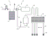
图1为本发明节能污水处理装置的第一实施例结构示意图;1 is a schematic structural diagram of the first embodiment of the energy-saving sewage treatment device of the present invention;
图2为发电机与蓄电池连接原理示意框图;Figure 2 is a schematic block diagram of the connection principle between the generator and the battery;
图3为发电装置结构示意图;Figure 3 is a schematic diagram of the structure of the power generation device;
图4为本发明节能污水处理装置第二实施例结构示意图;4 is a schematic structural diagram of the second embodiment of the energy-saving sewage treatment device of the present invention;
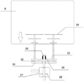
图5为本发明节能污水处理装置推动搅拌叶片的结构示意图;5 is a schematic structural diagram of the energy-saving sewage treatment device of the present invention pushing stirring blades;
图6为本发明节能污水处理装置收回搅拌叶片的结构示意图。6 is a schematic structural diagram of the energy-saving sewage treatment device of the present invention retracting the stirring blade.
1—污水处理器;10—吸水泵;11—吸水管道;12—出水管道;13—过滤箱;14—增压泵;15—排水管道;16—曝气室;17—网孔板;18—曝气管;19—曝气管头;100—进气管;1—sewage processor; 10—suction pump; 11—suction pipe; 12—outlet pipe; 13—filter box; 14—booster pump; 15—drainage pipe; 16—aeration chamber; 17—mesh plate; 18 - Aeration pipe; 19 - Aeration pipe head; 100 - Intake pipe;
2—发电装置;20—叶轮;21—发电机;22—叶轮室;23—大齿轮23;24—小齿轮;2—generating device; 20—impeller; 21—generator; 22—impeller chamber; 23—large gear 23; 24—pinion;
3—搅拌机构;30—顶块;31—转动轴;32—伸缩板;33—固定板;34—下滚动球体;3—stirring mechanism; 30—top block; 31—rotating shaft; 32—telescopic plate; 33—fixed plate; 34—lower rolling ball;
35—上滚动球体;36—复位弹簧;37—叶轮室;38—叶轮;39—搅拌叶片;4—好氧池。35—upper rolling ball; 36—return spring; 37—impeller chamber; 38—impeller; 39—stirring blade; 4—aerobic pool.
具体实施方式Detailed ways
为使本发明的目的、技术方案和优点更加清楚,下面将结合附图对本发明的技术方案进行清楚、完整的描述。显然,所描述的实施例仅是本发明的一部分实施例,而不是全部的实施例。基于本发明中的实施例,本领域普通技术人员在没有做出创造性劳动前提下所获得的所有其他实施例,都属于本发明保护的范围。In order to make the objectives, technical solutions and advantages of the present invention clearer, the technical solutions of the present invention will be described clearly and completely below with reference to the accompanying drawings. Obviously, the described embodiments are only some, but not all, embodiments of the present invention. Based on the embodiments of the present invention, all other embodiments obtained by those of ordinary skill in the art without creative efforts shall fall within the protection scope of the present invention.
在本发明的描述中,需要说明的是,术语“上”、“下”、“水平”等指示的方位或位置关系均为基于附图所示的方位或位置关系,仅仅是为了便于描述本发明和简化描述,而不是指示或暗示所指的装置或元件必须具有特定的方位、以特定的方位构造和操作,因此不能理解为对本发明的限制。In the description of the present invention, it should be noted that the orientation or positional relationship indicated by the terms "upper", "lower", "horizontal", etc. are all based on the orientation or positional relationship shown in the accompanying drawings, which are only for the convenience of describing the present invention. The invention and simplified description do not indicate or imply that the device or element referred to must have a particular orientation, be constructed and operate in a particular orientation, and therefore should not be construed as limiting the invention.
在本发明的描述中,需要说明的是,除非另有明确的规定和限定,术语“连接”应做广义理解,例如,可以是固定连接,也可以是可拆卸连接,或一体地连接;可以是直接相连,也可以通过中间媒介间接相连,可以是两个元件内部的连通。对于本领域的普通技术人员而言,可以具体情况理解上述术语在本发明中的具体含义。In the description of the present invention, it should be noted that, unless otherwise expressly specified and limited, the term "connection" should be understood in a broad sense, for example, it may be a fixed connection, a detachable connection, or an integral connection; It is directly connected, or it can be indirectly connected through an intermediate medium, and it can be the internal connection of two components. For those of ordinary skill in the art, the specific meanings of the above terms in the present invention can be understood in specific situations.
如图1-图3所示,一种节能污水处理装置,其包括:As shown in Figures 1 to 3, an energy-saving sewage treatment device includes:
一污水处理器1;a sewage processor 1;
一发电装置2,其与污水处理器1相连接;a power generation device 2, which is connected to the sewage treatment device 1;
污水处理器1利用其工作过程中产生的水压驱动装设于水流通道中的叶轮20旋转,叶轮20与发电装置2的发电机21输入端轴连接,进而带动发电机21输入端旋转,发电装置2进行自发电。The sewage treatment device 1 uses the water pressure generated during its operation to drive the
本技术方案污水处理器在污水处理过程中,高压水流驱动装设于水流通道中的叶轮旋转,叶轮与发电装置的发电机输入端轴连接,进而带动发电机输入端旋转,发电装置进行自发电,可以供外界使用,比如河流廊灯的照明使用。In the sewage treatment process of this technical solution, the high-pressure water flow drives the impeller installed in the water flow channel to rotate, and the impeller is connected with the generator input end of the power generation device, and then drives the input end of the generator to rotate, and the power generation device generates power by itself , can be used for external use, such as the lighting of river corridor lights.
另外,污水处理器1包括:In addition, the sewage treatment device 1 includes:
一吸水泵10;a
一叶轮室21,其与吸水泵10由吸水管道11相连通,叶轮20轴连接于叶轮室22内,该轴并向外延伸与外置的发电装置2的发电机21输入端相连接;An
一出水管道12,其与叶轮室22相连通。An
污水处理器1还包括设置于吸水泵10与叶轮室22之间的过滤箱13。过滤箱13主要用于清除污水过程中的杂物,防止进入叶轮室22,阻碍叶轮20工作,需要说明的是,此处的过滤箱13包括呈抽屉状的箱本体,其内过滤胆可抽出,进行定期清理或更换。The sewage treatment device 1 further includes a
出水管道12与一增压泵14相连通,增压泵14的排水端由排水管道15连通曝气室16,曝气室16内设有多层相互间隔的网孔板17,曝气室16的出水端连通至少一只曝气管18,曝气管18的出水端头连接设置曝气头19;出水管道12上还连通设置有进气管100,进气管100上设有流量比例阀。The
增压泵14将过滤后的污水高压冲入曝气室16,污水在管道高速流动过程中通过进气管100吸入空气,与大气混合后的污水在曝气室16内经过网孔板17逐级破坏,使得空气与污水混合充分,最后经过曝气头19爆出,冲入河流中,大量的富含氧的污水冲入河流,提高河流中污水的含氧量,进行污水治理。The booster pump 14 rushes the filtered sewage into the
较为优选地,网孔板17的孔径大小沿水流流动方向逐层变小。More preferably, the aperture size of the mesh plate 17 becomes smaller layer by layer along the water flow direction.
另外,由于水流在管道流动过程中会与管道内壁发生碰撞,速度或随着水流流程逐渐减弱,故排水管道15呈“S”型,并沿水流流动方向,排水管道15的管径逐渐减小,避免水流流速减弱太快。In addition, because the water flow will collide with the inner wall of the pipe during the flow of the pipe, and the speed may gradually weaken with the flow of the water flow, so the
发电装置2的发电机21的输出端与与一调节器的输入端相连,所述调节器的输出端与一蓄电池和/或一控制器总成相连,所述蓄电池和/或所述控制器总成与河流廊灯相连。The output end of the
叶轮20的传动轴与发电机21输入端传动连接处设有大、小齿轮增速传动件,大齿轮23与叶轮20的传动轴相连接,小齿轮24与发电机21的输出端相连接,大、小齿轮23,24相互啮合。The transmission connection between the transmission shaft of the
调节器包括单片机,所述单片机与所述蓄电池之间还串接有整流滤波稳压电路。The regulator includes a single-chip microcomputer, and a rectifying, filtering, and voltage-stabilizing circuit is also connected in series between the single-chip microcomputer and the battery.
如图3至图6所示,实施例2:一种节能污水处理装置,在污水的吸水管道11或/和出水管道12上连接一叶轮室37,叶轮室37中的叶轮38与转动轴31的一端连接,转动轴31的另一端伸出叶轮室37并与一搅拌机构3连接,搅拌机构3对好氧池4中的污水进行搅拌。As shown in Figures 3 to 6, Embodiment 2: an energy-saving sewage treatment device, an
搅拌机构3包括伸缩板32、固定板33、顶块30、复位弹簧36以及搅拌叶片39;固定板33固定在转动轴31上并随着转动轴31转动而转动,伸缩板32安装在转动轴31并且能够沿着转动轴31的轴向移动;固定板33上表面设有两个下滚动球体34,两个下滚动球体34位于固定板33任意一直径的两端,伸缩板32下表面设有两个上滚动球体35,两个上滚动球体35位于伸缩板32任意一直径的两端,固定板33转动的过程中通过下滚动球体34顶起伸缩板32的上滚动球体35使得伸缩板32远离固定板33;搅拌叶片39一端固定在伸缩板32上,搅拌叶片39另一端位于好氧池4中。在转动轴31的另一端还固定一顶块30和复位弹簧36,复位弹簧36夹持在顶块30与伸缩板32之间;当上滚动球体35与下滚动球体34接触并使得伸缩板32远离固定板33时,复位弹簧36被挤压,当上滚动球体35与下滚动球体34分离时,复位弹簧36将伸缩板32推回原位。The
本发明节能污水处理装置的工作方法如下:叶轮室37中的叶轮叶片39在污水的冲刷下转动,转动的叶轮叶片39带动转动轴31一直转动,转动的转动轴31再带动固定板33也随之转动。固定板33上的下滚动球体34与伸缩板32下方的上滚动球体35逐渐接触后,伸缩板32和上滚动球体35被抬起。由于伸缩板32抬起后,其上的搅拌叶片39也随之向前移动,并且此时,复位弹簧36被挤压。当固定板33上的下滚动球体34与伸缩板32下方的上滚动球体35逐渐分离,伸缩板32失去了固定板33的推力,复位弹簧36弹性势能释放并将伸缩板32和搅拌叶片39推回原始位置并且使得上滚动球体35又位于下滚动球体34运动轨迹上,上述运动过程重复使得伸缩板32来回运动,并且也使得搅拌叶片39也来回运动,对好氧池进行搅拌提高污水的含氧量。The working method of the energy-saving sewage treatment device of the present invention is as follows: the
一种污水处理系统,包括过滤箱13,过滤箱13设有吸水管道11和出水管道12,吸水管道11上设有吸水泵10,出水管道12上设有任何一项节能污水处理装置。A sewage treatment system includes a
过滤箱13包括呈抽屉状的箱本体,其内过滤胆可抽出,进行定期清理或更换。The
最后应说明的是:以上实施例仅用以说明本发明的技术方案,而非对其限制;尽管参照前述实施例对本发明进行了详细的说明,本领域的普通技术人员应当理解:其依然可以对前述实施例所记载的技术方案进行修改,或者对其中部分或者全部技术特征进行等同替换;而这些修改或者替换,并不使相应技术方案的本质脱离本发明实施例技术方案的范围。Finally, it should be noted that the above embodiments are only used to illustrate the technical solutions of the present invention, but not to limit them; although the present invention has been described in detail with reference to the foregoing embodiments, those of ordinary skill in the art should understand that it can still be The technical solutions described in the foregoing embodiments are modified, or some or all of the technical features thereof are equivalently replaced; and these modifications or replacements do not make the essence of the corresponding technical solutions depart from the scope of the technical solutions of the embodiments of the present invention.
Claims (3)
Priority Applications (1)
| Application Number | Priority Date | Filing Date | Title |
|---|---|---|---|
| CN201711447868.6A CN108083421B (en) | 2017-12-27 | 2017-12-27 | Energy-saving sewage treatment device and system |
Applications Claiming Priority (1)
| Application Number | Priority Date | Filing Date | Title |
|---|---|---|---|
| CN201711447868.6A CN108083421B (en) | 2017-12-27 | 2017-12-27 | Energy-saving sewage treatment device and system |
Publications (2)
| Publication Number | Publication Date |
|---|---|
| CN108083421A CN108083421A (en) | 2018-05-29 |
| CN108083421B true CN108083421B (en) | 2020-11-10 |
Family
ID=62179857
Family Applications (1)
| Application Number | Title | Priority Date | Filing Date |
|---|---|---|---|
| CN201711447868.6A Expired - Fee Related CN108083421B (en) | 2017-12-27 | 2017-12-27 | Energy-saving sewage treatment device and system |
Country Status (1)
| Country | Link |
|---|---|
| CN (1) | CN108083421B (en) |
Families Citing this family (1)
| Publication number | Priority date | Publication date | Assignee | Title |
|---|---|---|---|---|
| CN112833619B (en) * | 2020-12-30 | 2022-07-29 | 天津天发总厂机电设备有限公司 | Hydroelectric set tail water residual pressure water supply cooling system |
Citations (6)
| Publication number | Priority date | Publication date | Assignee | Title |
|---|---|---|---|---|
| KR100679876B1 (en) * | 2005-10-20 | 2007-02-07 | 이영우 | Gas Dissolution Reactor |
| CN202577493U (en) * | 2012-05-23 | 2012-12-05 | 王旭 | Anti-blocking device of sewer |
| CN203613057U (en) * | 2013-11-27 | 2014-05-28 | 曲靖宏程工贸有限公司 | Multi-level purification device for tap water |
| CN105080210A (en) * | 2015-07-17 | 2015-11-25 | 浙江省海洋水产研究所 | Aerated filtration treatment device for aquaculture wastewater |
| CN106870254A (en) * | 2017-03-08 | 2017-06-20 | 钟浪雅 | A kind of high efficiency water power electricity generating system |
| CN206447738U (en) * | 2017-02-14 | 2017-08-29 | 延相东 | A kind of landscape spray pond |
-
2017
- 2017-12-27 CN CN201711447868.6A patent/CN108083421B/en not_active Expired - Fee Related
Patent Citations (6)
| Publication number | Priority date | Publication date | Assignee | Title |
|---|---|---|---|---|
| KR100679876B1 (en) * | 2005-10-20 | 2007-02-07 | 이영우 | Gas Dissolution Reactor |
| CN202577493U (en) * | 2012-05-23 | 2012-12-05 | 王旭 | Anti-blocking device of sewer |
| CN203613057U (en) * | 2013-11-27 | 2014-05-28 | 曲靖宏程工贸有限公司 | Multi-level purification device for tap water |
| CN105080210A (en) * | 2015-07-17 | 2015-11-25 | 浙江省海洋水产研究所 | Aerated filtration treatment device for aquaculture wastewater |
| CN206447738U (en) * | 2017-02-14 | 2017-08-29 | 延相东 | A kind of landscape spray pond |
| CN106870254A (en) * | 2017-03-08 | 2017-06-20 | 钟浪雅 | A kind of high efficiency water power electricity generating system |
Also Published As
| Publication number | Publication date |
|---|---|
| CN108083421A (en) | 2018-05-29 |
Similar Documents
| Publication | Publication Date | Title |
|---|---|---|
| CN206308098U (en) | A kind of solar energy aeration reoxygenation device for sanitary sewage disposal | |
| CN205368020U (en) | Fine motion power dispersibility sewage treatment integrated device based on scene is complementary | |
| CN202705187U (en) | Buried concrete combined type sewage disposal system | |
| CN209759229U (en) | Sewage treatment equipment with automatic stirring function | |
| CN108033547B (en) | A kind of control method of energy-saving sewage treatment device | |
| CN108083421A (en) | An energy-saving sewage treatment device | |
| CN219469816U (en) | Water body sedimentation device for reservoir outlet | |
| CN207596547U (en) | Non-energy-consumption formula flowing polluted water body prosthetic device | |
| US20100327590A1 (en) | Electricity generating apparatus using bubble buoyancy | |
| CN208648924U (en) | A kind of municipal domestic sewage treatment device | |
| CN217895260U (en) | River channel treatment diving shock wave overflowing system based on Internet of things | |
| CN216155693U (en) | New energy distributed domestic sewage purification device | |
| CN207632589U (en) | Automatically adjust water level, Non-energy-consumption flowing polluted water body prosthetic device | |
| CN207061969U (en) | Solar energy black and odorous water purifier vessel | |
| CN201087153Y (en) | Surface aeration impeller liftable sewage biological purification device with ventilation pipe | |
| CN205687656U (en) | A kind of river water body purifies compound aerator | |
| CN205473227U (en) | River water purification system | |
| CN116282734A (en) | A mobile treatment device for the treatment of black and odorous water in rural areas | |
| CN110835201A (en) | Black and odorous water body treatment system | |
| CN107162336B (en) | Artificial wetland for purifying community wastewater by self-circulation | |
| CN206502633U (en) | A kind of lake solar energy high energy gas water purification system | |
| CN221451799U (en) | Integrated sewage treatment equipment with aeration function | |
| CN105668821A (en) | Composite aerator for river water purification | |
| CN219297334U (en) | An energy-saving sewage treatment device | |
| CN213112954U (en) | Utilize multistage sewage treatment integrated device of photosynthetic microorganism technique |
Legal Events
| Date | Code | Title | Description |
|---|---|---|---|
| PB01 | Publication | ||
| PB01 | Publication | ||
| SE01 | Entry into force of request for substantive examination | ||
| SE01 | Entry into force of request for substantive examination | ||
| TA01 | Transfer of patent application right | ||
| TA01 | Transfer of patent application right |
Effective date of registration: 20201021 Address after: Room 504, No.137, Hongxing Road, Hefei City, Anhui Province Applicant after: Anhui Qibing Ecological Treatment Engineering Co.,Ltd. Address before: No. 55, No. 55, Xinghai South Road, Zhejiang hi tech Zone, Zhejiang Province, 16-11 Applicant before: NINGBO YONGCHENG INTELLIGENT TECHNOLOGY Co.,Ltd. |
|
| GR01 | Patent grant | ||
| GR01 | Patent grant | ||
| CF01 | Termination of patent right due to non-payment of annual fee | ||
| CF01 | Termination of patent right due to non-payment of annual fee |
Granted publication date: 20201110 |