CN108030422B - Shower bath - Google Patents
Shower bath Download PDFInfo
- Publication number
- CN108030422B CN108030422B CN201810011385.XA CN201810011385A CN108030422B CN 108030422 B CN108030422 B CN 108030422B CN 201810011385 A CN201810011385 A CN 201810011385A CN 108030422 B CN108030422 B CN 108030422B
- Authority
- CN
- China
- Prior art keywords
- shower
- assembly
- connecting piece
- water
- top spraying
- Prior art date
- Legal status (The legal status is an assumption and is not a legal conclusion. Google has not performed a legal analysis and makes no representation as to the accuracy of the status listed.)
- Active
Links
Images
Classifications
-
- A—HUMAN NECESSITIES
- A47—FURNITURE; DOMESTIC ARTICLES OR APPLIANCES; COFFEE MILLS; SPICE MILLS; SUCTION CLEANERS IN GENERAL
- A47K—SANITARY EQUIPMENT; ACCESSORIES THEREFOR, e.g. TOILET ACCESSORIES
- A47K3/00—Baths; Showers; Appurtenances therefor
- A47K3/28—Showers or bathing douches
-
- A—HUMAN NECESSITIES
- A47—FURNITURE; DOMESTIC ARTICLES OR APPLIANCES; COFFEE MILLS; SPICE MILLS; SUCTION CLEANERS IN GENERAL
- A47K—SANITARY EQUIPMENT; ACCESSORIES THEREFOR, e.g. TOILET ACCESSORIES
- A47K3/00—Baths; Showers; Appurtenances therefor
- A47K3/28—Showers or bathing douches
- A47K3/281—Accessories for showers or bathing douches, e.g. cleaning devices for walls or floors of showers
Landscapes
- Health & Medical Sciences (AREA)
- Public Health (AREA)
- Epidemiology (AREA)
- General Health & Medical Sciences (AREA)
- Bathtubs, Showers, And Their Attachments (AREA)
- Nozzles (AREA)
Abstract
本发明公开一种淋浴器,其包括顶喷花洒组件、手持花洒组件及立杆;还包括一升降结构,该升降结构供顶喷花洒组件及手持花洒组件在立杆上滑移升降;该升降结构包括一连接件及限位部件;所述连接件供顶喷花洒组件及手持花洒组件的花洒座桥接;所述限位部件装接于顶喷花洒组件;所述立杆成型与限位部件相抵配的止位部,且该止位部沿立杆轴向间隔排布;本发明提供一种淋浴器,本发明所述的淋浴器利用简单的结构实现顶喷花洒与手持花洒联动滑移,并实现升降功能,以满足不同身高的使用者的使用需求;还实现单手操作驱动顶喷花洒与手持花洒的升降。
The invention discloses a shower, which includes a top spray assembly, a hand shower assembly and a pole; and also includes a lifting structure for the top spray assembly and the hand shower assembly to slide on the pole Lifting; the lifting structure includes a connecting piece and a limiting part; the connecting piece is used to bridge the shower seat of the top spray assembly and the hand shower assembly; the limiting part is attached to the top spray assembly; The stop part formed by the vertical rod and the stop part is matched with the stop part, and the stop part is arranged at intervals along the axial direction of the vertical rod; the invention provides a shower, and the shower in the invention uses a simple structure to realize the top The spray shower and the hand shower slide in linkage, and realize the lifting function to meet the needs of users of different heights; it also realizes one-handed operation to drive the lift of the top spray and the hand shower.
Description
技术领域technical field
本发明涉及卫浴行业,尤其与一种淋浴器有关。The invention relates to the bathroom industry, in particular to a shower.
背景技术Background technique
现有的淋浴器包括顶喷花洒、手持花洒及立杆,顶喷花洒一般与立杆固定,因此顶喷花洒的高度都是在淋浴器固定于墙体时限定的,手持花洒则通过固装在墙体的花洒座限定高度;故现有的淋浴器安装的整体高度都是安装人员按照一般人体身高进行限定安装,顶喷花洒及手持花洒的高度是固定的,无法进行高度调节,无法满足不同身高的使用者的使用需求,例如,对于身高高的人,头部接近或顶触顶喷花洒,使得淋浴时非常压抑,手持花洒设置的位置也同样偏低;对于身高较低的使用者,顶喷花洒高度过高,同样伴随着使用体验差的问题,尤其是对于酒店、公共浴室等地方,其使用者皆不同,体验效果是使用者选定该酒店或公共浴室的因素之一,因此现有的淋浴器需进一步改进,以弥补现有淋浴器的不足。Existing showers include overhead showers, hand-held showers and poles. The overhead showers are generally fixed to the poles, so the height of the overhead shower is limited when the shower is fixed on the wall. The hand-held shower The height of the sprinkler is limited by the shower seat fixed on the wall; therefore, the overall height of the existing shower installation is limited by the installer according to the height of the general human body, and the height of the top spray shower and the hand shower is fixed , the height cannot be adjusted, and it cannot meet the needs of users of different heights. For example, for tall people, the head is close to or the top touches the top of the shower, which makes the shower very depressing, and the position of the hand shower is also the same Low; for users with low stature, the height of the overhead shower is too high, which is also accompanied by the problem of poor user experience, especially for hotels, public bathrooms and other places, the users are different, and the experience effect depends on the user's choice. One of the factors that determine the hotel or public bathroom, so the existing shower needs to be further improved to make up for the deficiencies of the existing shower.
发明内容Contents of the invention
本发明的目的在于解决现有中的问题,提供一种淋浴器,其结构简单、设计合理且易实现,本发明所述的淋浴器利用简单的结构实现顶喷花洒与手持花洒联动滑移,并实现升降功能,以满足不同身高的使用者的使用需求;而且,本发明实现单手操作驱动顶喷花洒与手持花洒的升降。The purpose of the present invention is to solve the existing problems, and provide a shower with simple structure, reasonable design and easy realization. The shower according to the present invention uses a simple structure to realize the linkage and sliding of the top spray shower and the hand shower. Move, and realize the lifting function to meet the needs of users of different heights; moreover, the present invention realizes one-handed operation to drive the lifting of the overhead shower and the hand-held shower.
为达成上述目的,本发明采用如下技术方案:To achieve the above object, the present invention adopts the following technical solutions:
一种淋浴器,其包括顶喷花洒组件、手持花洒组件及立杆;还包括一升降结构,该升降结构供顶喷花洒组件及手持花洒组件在立杆上滑移升降;该升降结构包括一连接件及限位部件;所述连接件供顶喷花洒组件及手持花洒组件的花洒座桥接;所述限位部件装接于顶喷花洒组件;所述立杆成型与限位部件相抵配的止位部,且该止位部沿立杆轴向间隔排布;其中,所述顶喷花洒组件与手持花洒组件通过连接件相连,且沿立杆轴向滑移,并通过顶喷花洒组件上的限位部件与立杆的止位部抵配形成升降后定位。A shower, which includes a top-spray shower assembly, a hand-held shower assembly and a pole; it also includes a lifting structure, which allows the top-spray shower assembly and the hand-held shower assembly to slide and lift on the pole; the The lifting structure includes a connecting piece and a limiting part; the connecting piece is used to bridge the shower seat of the overhead shower assembly and the hand shower assembly; the limiting part is attached to the overhead shower assembly; the vertical rod The stop part is formed to match the limit part, and the stop part is arranged at intervals along the axial direction of the vertical pole; wherein, the top spray shower assembly and the hand shower assembly are connected through a connecting piece, and along the vertical pole axis Sliding in the direction, and the stop part on the top spray assembly is matched with the stop part of the vertical pole to form a positioning after lifting.
进一步地,所述顶喷花洒组件包括一顶喷支架及顶喷花洒;所述顶喷支架一端形成握持部,该握持部与立杆呈一角度设置,并与连接件相连;顶喷支架的另一端供顶喷花洒活动装接;所述限位部件装设在顶喷支架上,并与立杆上的止位部配合限位。Further, the top spray assembly includes a top spray bracket and a top spray shower; one end of the top spray bracket forms a grip part, which is set at an angle to the vertical pole and connected to the connecting piece; The other end of the top spray bracket is used for the movable attachment of the top spray shower; the limiting part is installed on the top spray bracket, and cooperates with the stop part on the vertical rod for position limitation.
进一步地,所述限位部件包括摆杆、支轴及第一弹簧;所述摆杆通过支轴装设在顶喷支架,且摆杆一端形成与所述止位部配合侧凸体,另一端形成被动部;该被动部与第一弹簧抵配,并受第一弹簧作用力使摆杆一端的侧凸体置于所述止位部形成限位。Further, the limit part includes a swing rod, a support shaft and a first spring; the swing rod is installed on the top spray bracket through the support shaft, and one end of the swing rod forms a side convex body that cooperates with the stop part, and the other One end forms a passive part; the passive part abuts against the first spring, and is forced by the first spring to place the side convex body at one end of the swing rod on the stop part to form a limit position.
进一步地,还包括第二弹簧,该第二弹簧作用在侧凸体背面与顶喷支架。Further, a second spring is also included, and the second spring acts on the back of the side convex body and the top spray bracket.
进一步地,包括至少两个所述第一弹簧及按压件,两个所述第一弹簧与侧凸体同侧设置;所述按压件穿设于顶喷支架,且与所述摆杆一端的被动部相配合。Further, it includes at least two first springs and pressing pieces, and the two first springs are arranged on the same side as the side convex body; The passive part matches.
进一步地,所述止位部为齿槽,且多个齿槽沿立杆轴向排布形成齿条;所述齿槽包括限位面及导引斜面,所述限位面供侧凸体挂接限位;所述导引斜面供侧凸体上升时滑动位移。Further, the stop part is a tooth groove, and a plurality of tooth grooves are arranged along the axial direction of the vertical rod to form a rack; the tooth groove includes a limit surface and a guiding inclined surface, and the limit surface is used for the lateral convex body Hitch limit; the guide slope is used for sliding displacement when the side convex body rises.
进一步地,还包括进水软管,该进水软管内置于立杆内,且进水软管的出水端内置在顶喷支架。Further, a water inlet hose is also included, the water inlet hose is built in the vertical pole, and the water outlet end of the water inlet hose is built in the top spray bracket.
进一步地,还包括一进水立管及过水套管,所述进水立管内置于立杆内;所述过水套管置于顶喷支架内,且密封套接于进水立管;所述过水套管随顶喷支架升降位移而沿进水立管密封滑动并过水。Further, it also includes a water inlet standpipe and a water-passing casing, the water-inlet standpipe is built in the vertical rod; the water-passing casing is placed in the top spray bracket, and the sealing sleeve is connected to the water inlet standpipe ; The water-passing sleeve pipe seals and slides along the water inlet standpipe along with the lifting and displacement of the top spray bracket and passes through the water.
进一步地,所述顶喷花洒通过过水轴与顶喷支架连接过水;所述过水轴设有过水进口及过水出口,所述过水进口与顶喷支架内的进水软管或过水套管连通,所述过水出口与顶喷花洒相导通。Further, the top spray shower is connected to the top spray bracket through the water shaft; the water shaft is provided with a water inlet and a water outlet, and the water inlet is connected to the water inlet in the top spray bracket The pipe or the water casing is connected, and the water outlet is connected with the top spray shower.
进一步地,所述连接件为连接杆,其垂直于顶喷支架的轴线装接;所述花洒座套设在连接杆。Further, the connecting piece is a connecting rod, which is installed perpendicular to the axis of the top spray bracket; the shower seat is sleeved on the connecting rod.
进一步地,所述花洒座套设在连接杆的侧部,且还设有一定位结构;该定位结构包括定位槽及定位珠,所述定位珠装设于花洒座上且相对于连接杆的侧端面,所述定位槽周向排布于连接杆的侧端部;其中,所述定位珠置于任一定位槽内,以使花洒座限位套接于连接杆。Further, the shower seat is set on the side of the connecting rod, and is also provided with a positioning structure; the positioning structure includes a positioning groove and a positioning bead, and the positioning bead is installed on the shower seat and is opposite to the connecting rod. The positioning grooves are circumferentially arranged on the side ends of the connecting rod; wherein, the positioning beads are placed in any positioning groove, so that the shower seat is limitedly sleeved on the connecting rod.
进一步地,还包括一手机支架,该手机支架可转动地套接在连接件上。Further, a mobile phone support is also included, and the mobile phone support is rotatably sleeved on the connecting piece.
进一步地,还包括一化妆镜,该化妆镜可转动地套接在连接件上。Further, a vanity mirror is also included, and the vanity mirror is rotatably sleeved on the connecting piece.
进一步地,还包括一迫紧调节件,该迫紧调节件穿设手机支架或化妆镜,并通过螺纹迫紧手机支架或化妆镜套夹连接件。Further, it also includes a tightening adjustment part, which passes through the mobile phone bracket or the vanity mirror, and tightens the mobile phone bracket or the vanity mirror clip connecting part through threads.
进一步地,还包括一摩擦套,该摩擦套装设在手机支架与连接件之间或装设在化妆镜与连接件之间。Further, a friction sleeve is also included, and the friction sleeve is arranged between the mobile phone bracket and the connecting piece or between the vanity mirror and the connecting piece.
本发明所述的技术方案相对于现有技术,取得的有益效果是:Compared with the prior art, the technical solution of the present invention has the beneficial effects of:
(1)本发明提供一种淋浴器,其结构简单、设计合理且易实现,本发明所述的淋浴器利用简单的结构实现顶喷花洒与手持花洒联动滑移,并实现升降功能,以满足不同身高的使用者的使用需求;另外,本发明实现在低位控制整个顶喷花洒升降,便于身高较低的使用者使用,而且只需单手便能操作;(1) The present invention provides a shower, which is simple in structure, reasonable in design and easy to implement. The shower of the present invention uses a simple structure to realize the linkage sliding of the top spray shower and the hand shower, and realize the lifting function. To meet the needs of users of different heights; in addition, the present invention realizes the control of the entire overhead shower at a low position, which is convenient for users with lower heights, and can be operated with only one hand;
(2)本发明利用顶喷支架上的握持部与立杆呈一角度设置,实现升降时更省力,另外只需单手握住所述握持部形成操作,在简单结构的前提上,还能实现较高的使用体验,进一步提升本发明的创新度;(2) In the present invention, the grip part on the top spray bracket is set at an angle with the vertical pole, which saves more effort when lifting, and only needs to hold the grip part with one hand to form an operation. On the premise of a simple structure, It can also achieve a higher user experience and further enhance the degree of innovation of the present invention;
(3)本发明利用杠杆原理,轻松实现顶喷花洒在升降后进行限位,部件少,尤其是内部需联动的部件少,保证整体结构更加稳定可靠;使用时,只需轻松按压或松开摆杆的被动部,使得摆杆另一端的侧凸体嵌挂或脱离立杆上的止位部,以实现升降及升降后的限位;(3) The present invention utilizes the principle of leverage to easily realize the limit position of the top-spray sprinkler after lifting, with fewer parts, especially less internal parts that need to be linked, ensuring a more stable and reliable overall structure; Open the passive part of the swing rod, so that the side convex body at the other end of the swing rod is embedded or separated from the stop part on the vertical rod, so as to realize the lifting and the limit after lifting;
(4)本发明还利用第二弹簧增加侧凸体与止位部限位嵌配的稳定性及安全性;(4) The present invention also utilizes the second spring to increase the stability and safety of the limit fit between the side convex body and the stop part;
(5)本发明选用至少两个第一弹簧的作用力来提升摆杆上侧凸体与止位部配合的强度,不易受外力而脱离,安全性佳;(5) The present invention selects the active force of at least two first springs to increase the strength of the cooperation between the upper side convex body and the stop part of the swing rod, which is not easy to be separated by external force, and has good safety;
(6)本发明采用齿槽所形成的齿条式止位部,利用齿槽的限位面和导引斜面配合,实现在上升过程中无需按压所述按压件,直接推动顶喷支架的握持部,使得侧凸体沿导引斜面引导上升,上升到位后自然落在限位面上形成定位,结构巧妙,省力,尤其是在上升过程中省去按压步骤,使得上升调节更便捷;(6) The present invention adopts the rack-type stop part formed by the tooth groove, and utilizes the cooperation of the limit surface of the tooth groove and the guide inclined surface to realize that there is no need to press the pressing part during the rising process, and directly push the grip of the top spray bracket. The holding part makes the side convex body rise along the guiding slope, and after rising to the position, it naturally falls on the limit surface to form a positioning. The structure is ingenious and labor-saving, especially the pressing step is omitted during the rising process, making the rising adjustment more convenient;
(7)本发明采用两种结构实现进水结构,实现在顶喷花洒在升降时,其外表不会裸露出在外,结构设计巧妙、简单,且能够保持整体的美观度;(7) The present invention adopts two structures to realize the water inlet structure, so that when the top sprinkler is raised and lowered, its appearance will not be exposed, the structural design is ingenious and simple, and the overall aesthetics can be maintained;
(8)本发明的顶喷花洒与方形的顶喷支架配合,不仅实现顶喷花洒使用时的角度调节,还利用过水轴实现在无论转动到何种角度都能保持过水。(8) The overhead shower of the present invention cooperates with the square overhead shower bracket, which not only realizes the angle adjustment of the overhead shower when in use, but also uses the water passing shaft to keep the water flowing no matter what angle it rotates to.
(9)本发明采用杆式连接件,不仅便于推动顶喷支架升降时便于握持,还可供花洒座套设,整体结构简单、合理;(9) The present invention adopts a rod-type connecting piece, which is not only convenient to hold when pushing the top spray support up and down, but also can be used for the shower seat, and the overall structure is simple and reasonable;
(10)本发明还通过定位结构实现花洒座转动调节角度定位,避免在手持花洒在使用时因花洒座无定位而旋转,进而防止从花洒座中掉落;(10) The present invention also realizes the rotation adjustment angle positioning of the shower seat through the positioning structure, so as to avoid the rotation of the shower seat without positioning when the hand-held shower is in use, thereby preventing falling from the shower seat;
(11)本发明还增加了供手机、Ipad等电子设备置放的支架,提升用户使用体验;(11) The present invention also increases the brackets for placing electronic devices such as mobile phones and Ipads to improve user experience;
(12)本发明还增加化妆镜,该化妆镜套设连接件上,供使用者在清洁脸部时使用;(12) The present invention also adds a vanity mirror, which is sheathed on the connecting piece for the user to use when cleaning the face;
(13)本发明还提供迫紧调节件来调节化妆镜或手机支架来调节套夹力,便于化妆镜及手机支架角度调节,使得整体产品的体验更具人性化;(13) The present invention also provides a tightening adjustment member to adjust the clamping force of the vanity mirror or the mobile phone bracket, which is convenient for adjusting the angle of the vanity mirror and the mobile phone bracket, making the experience of the overall product more humanized;
(14)本发明还增设有摩擦套,为了保证产品外观,淋浴器本体表面一般都采用镀锌工艺,通过摩擦套使得套设在连接杆上的部件都不会因转动而刮伤连接杆表面,起到保护作用;(14) The present invention is additionally equipped with a friction sleeve. In order to ensure the appearance of the product, the surface of the shower body is generally galvanized. Through the friction sleeve, the parts set on the connecting rod will not scratch the surface of the connecting rod due to rotation. , play a protective role;
附图说明Description of drawings
此处所说明的附图用来提供对本发明的进一步理解,构成本发明的一部分,本发明的示意性实施例及其说明用于解释本发明,并不构成对本发明的不当限定。在附图中:The accompanying drawings described here are used to provide a further understanding of the present invention, and constitute a part of the present invention. The schematic embodiments of the present invention and their descriptions are used to explain the present invention, and do not constitute improper limitations to the present invention. In the attached picture:
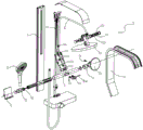
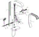
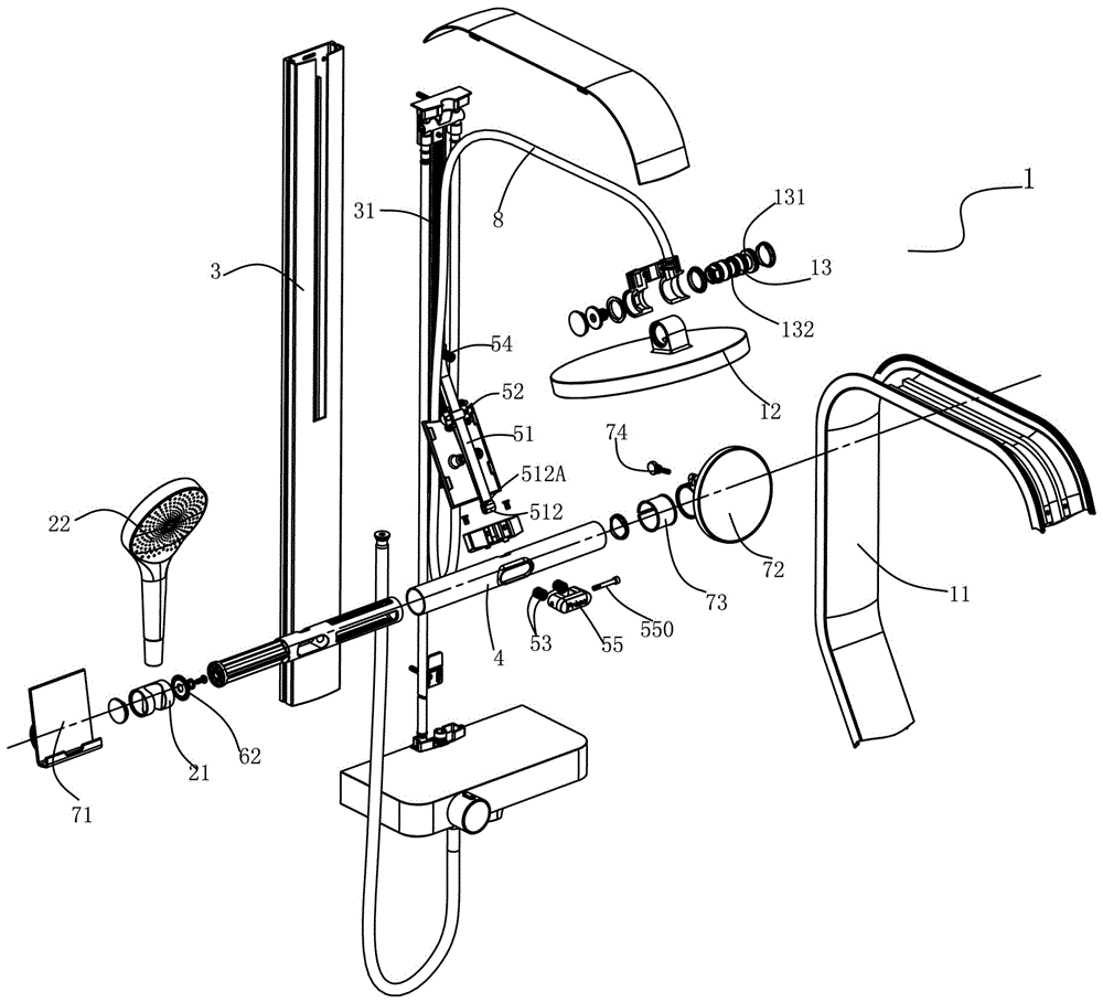
图1为本发明所述淋浴器的立体分解结构示意图;Fig. 1 is a schematic diagram of a three-dimensional exploded structure of a shower according to the present invention;
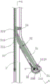
图2为本发明所述升降结构的剖视图;Fig. 2 is a cross-sectional view of the lifting structure of the present invention;
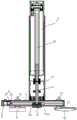
图3为本发明图2中A-A剖视图;Fig. 3 is A-A sectional view among Fig. 2 of the present invention;
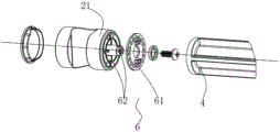
图4为本发明所述定位结构的立体分解图;Fig. 4 is a three-dimensional exploded view of the positioning structure of the present invention;
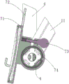
图5为本发明所述手机支架、化妆镜与连接杆配合的剖视图;Fig. 5 is a cross-sectional view of the cooperation between the mobile phone holder, the vanity mirror and the connecting rod according to the present invention;
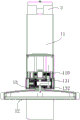
图6为本发明所述顶喷花洒与顶喷支架过水状态的剖视图;Fig. 6 is a cross-sectional view of the water-passing state of the top spray sprinkler and the top spray support according to the present invention;
图7为本发明实施例一的立体分解结构示意图;7 is a schematic diagram of a three-dimensional exploded structure of Embodiment 1 of the present invention;
图8为本发明实施例一的立体剖视结构示意图;FIG. 8 is a schematic perspective view of a three-dimensional cross-sectional structure of Embodiment 1 of the present invention;
图9为本发明实施例二的立体剖视结构示意图。FIG. 9 is a schematic perspective view of the structure of the second embodiment of the present invention.
具体实施方式Detailed ways
为了使本发明所要解决的技术问题、技术方案及有益效果更加清楚、明白,以下结合附图和实施例,对本发明进行进一步详细说明。应当理解,此处所描述的具体实施例仅用以解释本发明,并不用于限定本发明。In order to make the technical problems, technical solutions and beneficial effects to be solved by the present invention clearer and clearer, the present invention will be further described in detail below in conjunction with the accompanying drawings and embodiments. It should be understood that the specific embodiments described here are only used to explain the present invention, not to limit the present invention.
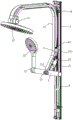
如图1至图3所示,本发明所述一种淋浴器,其包括顶喷花洒组件1、手持花洒组件2及立杆3;As shown in Figures 1 to 3, a shower according to the present invention includes a top shower assembly 1, a hand shower assembly 2 and a
还包括一升降结构,该升降结构供顶喷花洒组件1及手持花洒组件2在立杆3上滑移升降;It also includes a lifting structure, which is used for the overhead shower assembly 1 and the hand shower assembly 2 to slide and lift on the
该升降结构包括一连接件4及限位部件5;所述连接件4供顶喷花洒组件1及手持花洒组件2的花洒座21桥接;The lifting structure includes a connecting
所述立杆3上成型与限位部件5相抵配的止位部31,且该止位部31沿立杆3轴向间隔排布;所述止位部31为齿槽,且多个齿槽沿立杆3轴向排布形成齿条31;所述齿槽包括限位面311及导引斜面312,所述限位面311供侧凸体511挂接限位;所述导引斜面312供侧凸体511上升时滑动位移。The
所述顶喷花洒组件1包括一顶喷支架11及顶喷花洒12;所述顶喷支架11为方形或多边形状顶喷支架11(本发明以方形顶喷支架11为例,但不仅限于方形,其他形状亦属于本发明的保护范围),所述顶喷支架11一端形成握持部111,该握持部111与立杆3呈一角度设置,并与连接件4相连(本发明中顶喷支架11向外倾斜延伸,使得操作时更方便);顶喷支架11的另一端供顶喷花洒12活动装接;所述限位部件5装设在顶喷支架11上,并与立杆3的止位部31配合限位;本发明的限位部件5以杠杆结构为例,但不仅限于通过杠杆结构与立杆3上的止位部31配合,其他能够实现嵌入、挂接、插入于止位部31并形成限位配合的结构都属于本发明的保护范围;所述限位部件5包括摆杆51、支轴52及第一弹簧53;所述摆杆51通过支轴52装设在顶喷支架11,且摆杆51一端形成与所述止位部31配合侧凸体511,另一端形成被动部512;该被动部512与第一弹簧53抵配,并受第一弹簧53作用力使摆杆51一端的侧凸体511置于所述止位部31形成限位;The top spray assembly 1 includes a top spray support 11 and a top spray shower 12; the top spray support 11 is a square or polygon top spray support 11 (the present invention takes the square top spray support 11 as an example, but not only limited to a square shape, other shapes also belong to the protection scope of the present invention), one end of the top spray support 11 forms a grip 111, and the grip 111 is arranged at an angle with the vertical rod 3 and is connected with the connector 4 (the present invention The middle top spray support 11 extends obliquely outwards, making it more convenient to operate); the other end of the top spray support 11 is used for the top spray shower 12 to be movably attached; the limiting part 5 is installed on the top spray support 11, and Cooperate with the stop part 31 of the vertical rod 3 to limit the position; the limit part 5 of the present invention takes the lever structure as an example, but it is not limited to cooperate with the stop part 31 on the vertical rod 3 through the lever structure, other can realize embedding, hanging The structure of connecting and inserting into the stop part 31 and forming a limit fit all belongs to the protection scope of the present invention; the limit part 5 includes a swing rod 51, a support shaft 52 and a first spring 53; the swing rod 51 passes through the support The shaft 52 is mounted on the top spray bracket 11, and one end of the swing rod 51 forms a side convex body 511 that cooperates with the stop portion 31, and the other end forms a passive portion 512; the passive portion 512 is mated with the first spring 53, and is The force of the first spring 53 makes the side convex body 511 at one end of the swing rod 51 placed on the stop portion 31 to form a limit position;
其中,所述顶喷花洒12组件1与手持花洒组件2通过连接件4相连,且沿立杆3轴向滑移,并通过顶喷花洒12组件1上的限位部件5与立杆3的止位部31抵配形成升降后定位。Wherein, the
更具体地,还包括第二弹簧54,该第二弹簧54作用在侧凸体511背面与顶喷支架11;More specifically, it also includes a
更具体地,包括至少两个所述第一弹簧53及按压件55,两个所述第一弹簧53与侧凸体511同侧设置;所述按压件55穿设于顶喷支架11,且与所述摆杆51一端的被动部512相配合;More specifically, at least two
更具体地,所述连接件4为连接杆,其垂直于顶喷支架11的轴线装设;所述花洒座21套设在连接杆4;所述花洒座21套设在连接杆4的侧端面,且还设有一定位结构6;如图4所示,该定位结构6包括定位槽61及定位珠62,所述定位珠62装设于花洒座21上且相对于连接杆4的侧端面,所述定位槽61周向排布于连接杆4的侧部;其中,所述定位珠62置于任一定位槽61内,以使花洒座21限位套接于连接杆4;More specifically, the connecting
更具体地,如图5所示,还包括一手机支架71及化妆镜72,该手机支架71及化妆镜72可转动地套接在连接件4上;More specifically, as shown in FIG. 5 , it also includes a
更具体地,还包括一迫紧调节件73,该迫紧调节件73穿设手机支架71或化妆镜72,并通过螺纹迫紧手机支架71或化妆镜72套夹连接件4;More specifically, it also includes a tightening
更具体地,还包括一摩擦套74,该摩擦套74装设在手机支架71与连接件4之间或装设在化妆镜72与连接件4之间;More specifically, it also includes a
更具体地,还包括进水软管8,该进水软管8内置于立杆3内,且进水软管8的出水端内置在顶喷支架11;More specifically, it also includes a
更具体地,还包括一进水立管91及过水套管92,所述进水立管91内置于立杆3内;所述过水套管92置于顶喷支架11内,且密封套接于进水立管91;所述过水套管92随顶喷支架11升降位移而沿进水立管91密封滑动并过水;More specifically, it also includes a
更具体地,如图6所示,所述顶喷花洒12通过过水轴13与方形顶喷支架11连接过水;所述过水轴13设有过水进口131及过水出口132,所述过水进口131与顶喷支架11内的进水软管8或过水套管92连通,所述过水出口132与顶喷花洒12相导通。More specifically, as shown in Figure 6, the
实施例一,如图1至8所示,本实施例中所述一种淋浴器,其主要包括以下部件:顶喷支架11、顶喷花洒12、过水轴13、花洒座21、手持花洒22、立杆3、齿条31、连接杆4、摆杆51、支轴52、第一弹簧53、第二弹簧54、按压件55及进水软管8;Embodiment 1, as shown in Figures 1 to 8, a shower described in this embodiment mainly includes the following components: a
实际装配与使用,首先,将立杆3固定于墙体,随时将进水软管8连接淋浴龙头(淋浴龙头为现有技术),进水软管8先延伸至立杆3顶部固定,随后向下延伸后进入到顶喷支架11内,顶喷支架11内设有进水通道110,进水软管8待安装好限位部件5再与进水通道110装接;For actual assembly and use, first, the
其次,将齿条31沿立杆3的轴线方向铺设,该齿条31的每个齿槽都形成有导引斜面312及限位面311;而后把支轴52穿过摆杆51,再把摆杆51固定在顶喷支架11内,使得摆杆51以支轴52为支点形成杠杆摆动;随后将第一弹簧53件装设顶喷支架11内,并作用于摆杆51的被动部512(本发明以两组第一弹簧53为例,利用双弹簧力来保证摆杆51限位后的稳定性),而第二弹簧54也同样方式装入,且作用在摆杆51侧凸体511的背面;再把按压件55装设在顶喷支架11,并一端抵于所述被动部512(按压件55通过连轴510与被动部512连接,由于顶喷支架11的握持部111与立杆3呈一定角度倾斜,被动部512运动轨迹为斜线或弧线,故在被动部512供连轴510穿过的位置设置让位孔512A,以保证摆杆正常使用,不会产生卡死现象),另一端裸露于顶喷支架11外,以供人手操作按压;再把装配好的顶喷支架11对接上进水软管8后,滑套在立杆3上,同时使得摆杆51的侧凸体511嵌挂在齿条31的限位面311上;Secondly, the rack 31 is laid along the axial direction of the vertical rod 3, and each tooth groove of the rack 31 is formed with a guide slope 312 and a limit surface 311; then the support shaft 52 passes through the swing rod 51, and then The swing rod 51 is fixed in the top spray bracket 11, so that the swing rod 51 forms a lever swing with the fulcrum 52 as the fulcrum; then the first spring 53 is installed in the top spray bracket 11, and acts on the passive part 512 of the swing rod 51 (The present invention takes two groups of first springs 53 as an example, and utilizes the double spring force to ensure the stability of the fork 51 after the limit), and the second spring 54 is also loaded in the same way, and acts on the side convex body of the fork 51 511; then the pressing piece 55 is installed on the top spray bracket 11, and one end is against the passive part 512 (the pressing piece 55 is connected with the passive part 512 through the connecting shaft 510, because the grip part 111 of the top spray bracket 11 It is inclined at a certain angle with the vertical pole 3, and the movement track of the passive part 512 is an oblique line or an arc. Therefore, a
再次,所述连接杆4穿设固定或一体成型在顶喷支架11的握持部111,而后将花洒座21套设连接杆4的侧端部,为了防止因套夹力不足使得套设后仍可旋转,在花洒座21与连接杆4侧端部设置定位结构6,利用定位珠62与定位槽61配合实现转动后的定位;Again, the connecting
最后,将顶喷花洒12与顶喷支架11连接;顶喷花洒12与顶喷支架11通过过水轴13相接过水,顶喷花洒12可以绕过水轴13实现角度调节,同时过水轴13上的过水进口131连通所述进水通道110,而过水出口132导通顶喷花洒12。Finally, the
此外,本实施例还增加以下结构与功能:在连接杆4处还套设了供移动设备置放的手机支架71和化妆镜72,以增加使用者的置物需求和面部清洁时照镜需求;同时实施例为了防止连接杆4表面与手机支架71或化妆镜72的摩擦刮伤,在连接杆4上线套设软质的摩擦套74,手机支架71或化妆镜72直接套设在摩擦套74上;此外,本实施例中还增设有迫紧调节件73,其用于插接在手机支架71或者化妆镜72上,利用螺纹实现调节手机支架71与连接杆4的夹持力,防止因夹持力过小,使得手机支架71上的物品掉落;化妆镜72同样如此,可进行松紧调节,以调整不同的角度来适应不同的使用者。In addition, this embodiment also adds the following structures and functions: a
实际升降调节时,只需单手按压所述按压件55,按压件55向第一弹簧53方向位移,并使所述被动部512克服第一弹簧53的作用力,同时也使摆杆51克服所述侧凸体511背面的第二弹簧54的作用力,进而让摆杆51上侧凸体511脱离齿条31的限位面311,随后便可进行下降调节,待调节完毕后,松开按压件55,摆杆51在第一、第二弹簧53、54的作用力下,再次使侧凸体511嵌挂在齿条31的限位面311上,形成限位配合(此时的进水软管8向下延伸状态,同时手持花洒22也因连接杆4下降);当需要上升调节时,只需向上推动顶喷支架11,都无需进行对按压件55的按压,在上推过程中,由于齿条31的导引斜面312,使得侧凸体511沿导引斜面312的引导向上位移,直至调整到合适高度后,松开顶喷支架11,侧凸体511自然落在限位面311上形成限位挂接;上述整个过程只需单手便能实现操作,驱动力下,尤其是上升调节的驱动力,都无需按压,只需专心推动即可,连接杆4亦作为施力握持部111,便于使用者操作;另外,本发明将连接杆4制备成空心结构,才套入材质轻便的塑料轴,不仅减小连接杆4的总量,减小侧凸体511与齿条31提挂的重量,在生产工艺和成本上都大幅度降低;During the actual lifting adjustment, you only need to press the pressing
实施例二,如图9所示,本实施例二中与实施例一大致相同,因此其相同的部分不再重复赘述,区别在于立杆3内的进水方式采用进水立管91和过水套管92配合实现,将进水立管91装设在立杆3内,并一端连接淋浴龙头,一端为自由开口端,而过水套管92则密封嵌套在进水立管91上,且连通顶喷支架11的进水通道110;过水套管92套设在进水立管91的部分,其长度大于顶喷支架11在立杆3上的升降高度,且始终保持过水套管92密封套设在进水立管91;Embodiment 2, as shown in Figure 9, in this embodiment 2 is roughly the same as Embodiment 1, so the same parts will not be repeated, and the difference is that the water inlet method in the
上述说明示出并描述了本发明的优选实施例,如前所述,应当理解本发明并非局限于本文所披露的形式,不应看作是对其他实施例的排除,而可用于各种其他组合、修改和环境,并能够在本文所述发明构想范围内,通过上述教导或相关领域的技术或知识进行改动。而本领域人员所进行的改动和变化不脱离本发明的精神和范围,则都应在本发明所附权利要求的保护范围内。The foregoing description shows and describes preferred embodiments of the present invention, and as previously stated, it is to be understood that the present invention is not limited to the form disclosed herein and should not be construed as excluding other embodiments but may be applied to various other embodiments. Combinations, modifications and circumstances, and can be modified within the scope of the inventive concept described herein, by the above teachings or by skill or knowledge in the relevant field. However, changes and changes made by those skilled in the art do not depart from the spirit and scope of the present invention, and should all be within the protection scope of the appended claims of the present invention.
Claims (14)
Priority Applications (1)
| Application Number | Priority Date | Filing Date | Title |
|---|---|---|---|
| CN201810011385.XA CN108030422B (en) | 2018-01-05 | 2018-01-05 | Shower bath |
Applications Claiming Priority (1)
| Application Number | Priority Date | Filing Date | Title |
|---|---|---|---|
| CN201810011385.XA CN108030422B (en) | 2018-01-05 | 2018-01-05 | Shower bath |
Publications (2)
| Publication Number | Publication Date |
|---|---|
| CN108030422A CN108030422A (en) | 2018-05-15 |
| CN108030422B true CN108030422B (en) | 2023-05-02 |
Family
ID=62099099
Family Applications (1)
| Application Number | Title | Priority Date | Filing Date |
|---|---|---|---|
| CN201810011385.XA Active CN108030422B (en) | 2018-01-05 | 2018-01-05 | Shower bath |
Country Status (1)
| Country | Link |
|---|---|
| CN (1) | CN108030422B (en) |
Families Citing this family (1)
| Publication number | Priority date | Publication date | Assignee | Title |
|---|---|---|---|---|
| CN111729796B (en) * | 2020-07-15 | 2025-02-25 | 厦门欧圣斯卫浴有限公司 | A stepless adjustment structure of a sliding seat and a shower system having the structure |
Citations (2)
| Publication number | Priority date | Publication date | Assignee | Title |
|---|---|---|---|---|
| CN204781146U (en) * | 2015-07-08 | 2015-11-18 | 宁波埃美柯铜阀门有限公司 | Take slide bar showerhead suit |
| CN206197848U (en) * | 2016-07-15 | 2017-05-31 | 九牧厨卫股份有限公司 | A kind of shower components |
Family Cites Families (5)
| Publication number | Priority date | Publication date | Assignee | Title |
|---|---|---|---|---|
| JP2002088834A (en) * | 2000-09-18 | 2002-03-27 | Hitachi Chem Co Ltd | Height adjustable shower equipment |
| ITBS20010105U1 (en) * | 2001-12-21 | 2003-06-21 | Sanicro S R L | COMBINED ASCENDER WITH PEAR HOLDER HEIGHT ADJUSTABLE SHOWER |
| CN202458105U (en) * | 2012-02-22 | 2012-10-03 | 九牧厨卫股份有限公司 | Lifting shower |
| CN105310578A (en) * | 2015-10-12 | 2016-02-10 | 珠海格力电器股份有限公司 | Lifting shower head |
| CN208625524U (en) * | 2018-01-05 | 2019-03-22 | 九牧厨卫股份有限公司 | a shower |
-
2018
- 2018-01-05 CN CN201810011385.XA patent/CN108030422B/en active Active
Patent Citations (2)
| Publication number | Priority date | Publication date | Assignee | Title |
|---|---|---|---|---|
| CN204781146U (en) * | 2015-07-08 | 2015-11-18 | 宁波埃美柯铜阀门有限公司 | Take slide bar showerhead suit |
| CN206197848U (en) * | 2016-07-15 | 2017-05-31 | 九牧厨卫股份有限公司 | A kind of shower components |
Also Published As
| Publication number | Publication date |
|---|---|
| CN108030422A (en) | 2018-05-15 |
Similar Documents
| Publication | Publication Date | Title |
|---|---|---|
| CN207295860U (en) | A kind of Portable rose fixed frame | |
| US10555643B1 (en) | Humanized control device applied to health shower device | |
| CN108030422A (en) | A kind of shower | |
| KR101006197B1 (en) | Articulated shower | |
| CN115247501A (en) | Adjustable spraying maintenance equipment for concrete building | |
| CN101254491A (en) | Bathing room hand-operated up-down movable shower | |
| CN201205238Y (en) | Multifunctional lifting bar | |
| CN213296526U (en) | Shower sprinkler convenient to adjust shower nozzle position | |
| WO1998014104A1 (en) | Device for water massaging shower in the form of a hoop generating converging jets | |
| KR200390233Y1 (en) | Slide Shower Hanger | |
| CN210238664U (en) | A lift-type combined shower rod device | |
| CN220266740U (en) | Shower sprinkler | |
| CN209129077U (en) | A kind of shower head lifting seat and shower bath | |
| CN211756150U (en) | Paint spraying device for furniture manufacturing | |
| CN210013284U (en) | Height-adjustable shower holder | |
| CN209996163U (en) | Bathroom cabinet convenient for washing hair | |
| CN202288041U (en) | Shower Lifting Column | |
| CN207653184U (en) | A kind of gard watering device | |
| CN208625524U (en) | a shower | |
| CN217615376U (en) | Angle-adjustable shower head | |
| CN215235095U (en) | Top-spraying and handheld universal multifunctional shower device | |
| CN223535819U (en) | A high-strength glass basin | |
| CN205495908U (en) | Multifunctional shower seat | |
| JP2002360321A (en) | Cane support device | |
| KR101134710B1 (en) | Moving device for shower-head |
Legal Events
| Date | Code | Title | Description |
|---|---|---|---|
| PB01 | Publication | ||
| PB01 | Publication | ||
| SE01 | Entry into force of request for substantive examination | ||
| SE01 | Entry into force of request for substantive examination | ||
| GR01 | Patent grant | ||
| GR01 | Patent grant |