CN108027208B - Heat treatment apparatus - Google Patents
Heat treatment apparatus Download PDFInfo
- Publication number
- CN108027208B CN108027208B CN201680051793.7A CN201680051793A CN108027208B CN 108027208 B CN108027208 B CN 108027208B CN 201680051793 A CN201680051793 A CN 201680051793A CN 108027208 B CN108027208 B CN 108027208B
- Authority
- CN
- China
- Prior art keywords
- conveyance
- conveying
- tray
- refrigerant
- upper member
- Prior art date
- Legal status (The legal status is an assumption and is not a legal conclusion. Google has not performed a legal analysis and makes no representation as to the accuracy of the status listed.)
- Active
Links
Images


Classifications
-
- C—CHEMISTRY; METALLURGY
- C21—METALLURGY OF IRON
- C21D—MODIFYING THE PHYSICAL STRUCTURE OF FERROUS METALS; GENERAL DEVICES FOR HEAT TREATMENT OF FERROUS OR NON-FERROUS METALS OR ALLOYS; MAKING METAL MALLEABLE, e.g. BY DECARBURISATION OR TEMPERING
- C21D9/00—Heat treatment, e.g. annealing, hardening, quenching or tempering, adapted for particular articles; Furnaces therefor
- C21D9/0062—Heat-treating apparatus with a cooling or quenching zone
-
- C—CHEMISTRY; METALLURGY
- C21—METALLURGY OF IRON
- C21D—MODIFYING THE PHYSICAL STRUCTURE OF FERROUS METALS; GENERAL DEVICES FOR HEAT TREATMENT OF FERROUS OR NON-FERROUS METALS OR ALLOYS; MAKING METAL MALLEABLE, e.g. BY DECARBURISATION OR TEMPERING
- C21D1/00—General methods or devices for heat treatment, e.g. annealing, hardening, quenching or tempering
-
- C—CHEMISTRY; METALLURGY
- C21—METALLURGY OF IRON
- C21D—MODIFYING THE PHYSICAL STRUCTURE OF FERROUS METALS; GENERAL DEVICES FOR HEAT TREATMENT OF FERROUS OR NON-FERROUS METALS OR ALLOYS; MAKING METAL MALLEABLE, e.g. BY DECARBURISATION OR TEMPERING
- C21D9/00—Heat treatment, e.g. annealing, hardening, quenching or tempering, adapted for particular articles; Furnaces therefor
- C21D9/0056—Furnaces through which the charge is moved in a horizontal straight path
-
- F—MECHANICAL ENGINEERING; LIGHTING; HEATING; WEAPONS; BLASTING
- F27—FURNACES; KILNS; OVENS; RETORTS
- F27B—FURNACES, KILNS, OVENS, OR RETORTS IN GENERAL; OPEN SINTERING OR LIKE APPARATUS
- F27B9/00—Furnaces through which the charge is moved mechanically, e.g. of tunnel type; Similar furnaces in which the charge moves by gravity
- F27B9/02—Furnaces through which the charge is moved mechanically, e.g. of tunnel type; Similar furnaces in which the charge moves by gravity of multiple-track type; of multiple-chamber type; Combinations of furnaces
- F27B9/028—Multi-chamber type furnaces
-
- F—MECHANICAL ENGINEERING; LIGHTING; HEATING; WEAPONS; BLASTING
- F27—FURNACES; KILNS; OVENS; RETORTS
- F27B—FURNACES, KILNS, OVENS, OR RETORTS IN GENERAL; OPEN SINTERING OR LIKE APPARATUS
- F27B9/00—Furnaces through which the charge is moved mechanically, e.g. of tunnel type; Similar furnaces in which the charge moves by gravity
- F27B9/02—Furnaces through which the charge is moved mechanically, e.g. of tunnel type; Similar furnaces in which the charge moves by gravity of multiple-track type; of multiple-chamber type; Combinations of furnaces
- F27B9/029—Multicellular type furnaces constructed with add-on modules
-
- F—MECHANICAL ENGINEERING; LIGHTING; HEATING; WEAPONS; BLASTING
- F27—FURNACES; KILNS; OVENS; RETORTS
- F27B—FURNACES, KILNS, OVENS, OR RETORTS IN GENERAL; OPEN SINTERING OR LIKE APPARATUS
- F27B9/00—Furnaces through which the charge is moved mechanically, e.g. of tunnel type; Similar furnaces in which the charge moves by gravity
- F27B9/12—Furnaces through which the charge is moved mechanically, e.g. of tunnel type; Similar furnaces in which the charge moves by gravity with special arrangements for preheating or cooling the charge
-
- F—MECHANICAL ENGINEERING; LIGHTING; HEATING; WEAPONS; BLASTING
- F27—FURNACES; KILNS; OVENS; RETORTS
- F27B—FURNACES, KILNS, OVENS, OR RETORTS IN GENERAL; OPEN SINTERING OR LIKE APPARATUS
- F27B9/00—Furnaces through which the charge is moved mechanically, e.g. of tunnel type; Similar furnaces in which the charge moves by gravity
- F27B9/14—Furnaces through which the charge is moved mechanically, e.g. of tunnel type; Similar furnaces in which the charge moves by gravity characterised by the path of the charge during treatment; characterised by the means by which the charge is moved during treatment
- F27B9/20—Furnaces through which the charge is moved mechanically, e.g. of tunnel type; Similar furnaces in which the charge moves by gravity characterised by the path of the charge during treatment; characterised by the means by which the charge is moved during treatment the charge moving in a substantially straight path tunnel furnace
- F27B9/26—Furnaces through which the charge is moved mechanically, e.g. of tunnel type; Similar furnaces in which the charge moves by gravity characterised by the path of the charge during treatment; characterised by the means by which the charge is moved during treatment the charge moving in a substantially straight path tunnel furnace on or in trucks, sleds, or containers
-
- F—MECHANICAL ENGINEERING; LIGHTING; HEATING; WEAPONS; BLASTING
- F27—FURNACES; KILNS; OVENS; RETORTS
- F27D—DETAILS OR ACCESSORIES OF FURNACES, KILNS, OVENS, OR RETORTS, IN SO FAR AS THEY ARE OF KINDS OCCURRING IN MORE THAN ONE KIND OF FURNACE
- F27D3/00—Charging; Discharging; Manipulation of charge
- F27D3/12—Travelling or movable supports or containers for the charge
-
- F—MECHANICAL ENGINEERING; LIGHTING; HEATING; WEAPONS; BLASTING
- F27—FURNACES; KILNS; OVENS; RETORTS
- F27D—DETAILS OR ACCESSORIES OF FURNACES, KILNS, OVENS, OR RETORTS, IN SO FAR AS THEY ARE OF KINDS OCCURRING IN MORE THAN ONE KIND OF FURNACE
- F27D9/00—Cooling of furnaces or of charges therein
-
- F—MECHANICAL ENGINEERING; LIGHTING; HEATING; WEAPONS; BLASTING
- F27—FURNACES; KILNS; OVENS; RETORTS
- F27B—FURNACES, KILNS, OVENS, OR RETORTS IN GENERAL; OPEN SINTERING OR LIKE APPARATUS
- F27B9/00—Furnaces through which the charge is moved mechanically, e.g. of tunnel type; Similar furnaces in which the charge moves by gravity
- F27B9/12—Furnaces through which the charge is moved mechanically, e.g. of tunnel type; Similar furnaces in which the charge moves by gravity with special arrangements for preheating or cooling the charge
- F27B2009/124—Cooling
Abstract
Provided is a heat treatment device which can be configured in a more compact manner. The heat treatment device (1) is provided with a refrigerant channel formation body (42) for forming a refrigerant channel (48) for supplying a refrigerant to a processed object (100). The refrigerant passage forming body (42) includes two or more upper members (50) and lower members (49) as refrigerant passage forming members, and these members (49) and (50) are configured to be displaced so as to be close to each other along a vertical direction (Z1) intersecting the conveying direction, thereby forming the refrigerant passage (48) in a state of accommodating the object to be processed (100). The members (49, 50) are configured to be displaced in a vertical direction (Z1) in a spaced manner, thereby allowing the object (100) to be processed in the transport direction (A1) to enter and exit the refrigerant passage (48).
Description
Technical Field
The present invention relates to a heat treatment apparatus for performing heat treatment and cooling treatment on an object to be treated.
Background
For example, a heat treatment apparatus for performing a heat treatment on a metal member or the like (a treatment target object) is known (for example, see patent document 1). The quenching apparatus as the heat treatment apparatus described in patent document 1 is configured to perform quenching treatment (rapid cooling treatment) on a heated treatment object. In the quenching treatment, the treatment object is disposed in a vertically extending portion in the duct. The processed object is cooled by the refrigerant passing through the pipe.
Documents of the prior art
Patent document
Patent document 1: japanese patent laid-open publication No. 2005-213646
Disclosure of Invention
Problems to be solved by the invention
The processing object is displaced in the axial direction (vertical direction) of the opening of the duct, and is taken into the duct. In the configuration described in patent document 1, a heating furnace is disposed above the duct. Therefore, the heating furnace, the conveyance path for conveying the treatment object from the heating furnace to the duct, and the duct are vertically arranged, and the apparatus becomes large in size.
In view of the above, an object of the present invention is to provide a heat treatment apparatus which can be configured to be smaller.
Means for solving the problems
(1) In order to solve the above problem, a heat treatment apparatus according to one aspect of the present invention includes a refrigerant passage forming body for forming a refrigerant passage for supplying a specific refrigerant to a target object passing through a conveyance path in a specific conveyance direction, the refrigerant passage forming body including two or more refrigerant passage forming members, the two or more refrigerant passage forming members being configured to be displaced so as to approach each other in a specific intersecting direction intersecting the conveyance direction, thereby forming the refrigerant passage in a state of accommodating the target object, and to be displaced so as to be spaced from each other in the intersecting direction, thereby allowing the target object in the conveyance direction to enter and exit with respect to the refrigerant passage.
According to this configuration, the direction in which the refrigerant passage extends is different from the conveyance direction of the object to be processed. Thus, the shape of the heat treatment device does not become excessively long in either the direction in which the refrigerant passage extends or the conveying direction. Therefore, the heat treatment apparatus can be further miniaturized. In addition, the two or more refrigerant passage forming members are displaced relative to each other so as to be spaced apart from each other in the specific intersecting direction, whereby the object to be treated can be moved in and out of the refrigerant passages. Therefore, it is not necessary to provide a robot or the like for moving the object to be treated into and out of the refrigerant passage. This enables further downsizing of the heat treatment apparatus.
(2) Preferably, in the heat treatment apparatus, the refrigerant passage extends in the intersecting direction including a vertical direction of the heat treatment apparatus, and the refrigerant passage is configured such that the coolant as the refrigerant flows upward from below.
According to this configuration, the cross direction and the transport direction are arranged perpendicular to each other. Thus, the refrigerant passage forming body can be formed into a vertically long shape, and therefore the size of the heat treatment apparatus in the horizontal direction can be further reduced. In addition, since the direction in which the supply pipe extends and the conveying direction are perpendicular to each other, the heat treatment apparatus does not have an excessively large shape in both the horizontal direction and the vertical direction. This enables further downsizing of the heat treatment apparatus. In addition, in the refrigerant passage, the refrigerant flows upward from below, and therefore the refrigerant can be raised more uniformly. This enables more uniform cooling of the object to be treated.
(3) More preferably, the heat treatment apparatus further includes a conveyance tray for conveying the object to be treated in the conveyance direction, and the conveyance tray is configured to cooperate with two or more of the refrigerant passage forming members to form the refrigerant passage.
According to this structure, the delivery tray forms a part of the refrigerant passage. Thus, a dedicated member for supporting the conveyance tray in the refrigerant passage is not required, and the heat treatment apparatus can be made smaller and simpler in structure.
(4) More preferably, the conveyance tray is configured to be arrangeable between two or more of the refrigerant passage forming members, and includes a support portion for supporting the object to be processed and a hole portion for passing the refrigerant therethrough.
According to this configuration, the object to be processed is disposed in the intermediate portion of the refrigerant passage. The refrigerant is supplied to the object through the hole. This makes it possible to reliably support the object to be treated in the refrigerant passage and to more reliably cool the object to be treated with the refrigerant.
(5) Preferably, the two or more refrigerant passage forming members include an upper member and a lower member disposed below the upper member, and the heat treatment apparatus further includes a vertical displacement mechanism for vertically displacing the upper member with respect to the lower member.
According to this structure, the refrigerant passage is formed by displacing the upper member toward the lower member by the up-down displacement mechanism. Further, the object to be treated can be exposed from the refrigerant channel forming body by being raised by the vertical displacement mechanism so as to separate the upper member from the lower member. This enables the object to be processed to be moved in and out along the conveyance direction.
(6) More preferably, the heat treatment apparatus further includes a conveyance mechanism for displacing the conveyance tray in the conveyance direction, wherein the conveyance mechanism includes a unit configured to be displaceable by the vertical displacement mechanism to a specific conveyance position and a specific cooling position, the unit supports the conveyance tray at the conveyance position so as to be spaced apart from the upper member and the lower member, and the conveyance tray is disposed so as to be in contact with the lower member at the cooling position.
According to this configuration, when the unit is disposed at the conveyance position, the unit can support the conveyance tray in a state where the conveyance tray does not collide with another member. This enables smooth conveyance of the conveyance tray. On the other hand, when the unit is disposed at the cooling position, the conveyance tray may be disposed so as to form the refrigerant passage in cooperation with the lower member. In this way, the vertical displacement mechanism can vertically displace the unit and the conveyance tray, as well as vertically displacing the upper member relative to the lower member.
(7) More preferably, the vertical displacement mechanism is configured to: the upper member is displaced so as to be brought into contact with the conveyance tray when the conveyance tray is located at the cooling position.
According to this configuration, the vertical displacement mechanism displaces the upper member downward, thereby allowing the upper member and the lower member to sandwich the conveyance tray. As a result, the refrigerant passage can be formed by the cooperation of the upper member, the delivery tray, and the lower member.
(8) Preferably, the heat treatment device further includes a rectifying member for rectifying the refrigerant in the refrigerant passage.
According to this configuration, the amount of the refrigerant contacting the object to be processed per unit time can be increased and equalized, and thus deformation of the object to be processed can be suppressed.
ADVANTAGEOUS EFFECTS OF INVENTION
According to the present invention, a smaller heat treatment apparatus can be realized.
Drawings
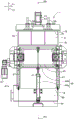
Fig. 1 is a schematic and conceptual perspective view of a heat treatment apparatus, a part of which is cut away.
Fig. 2 is a front view of a heating device of the heat treatment device.
Fig. 3 is an inlet side view of the heating device.
Fig. 4 is an outlet side view of the heating device.
Fig. 5 is a rear view of the heating device.
Fig. 6 is a partial sectional view of a main part of the heating apparatus viewed from the front side.
Fig. 7 is a sectional view of a state where a main part of the heating apparatus is viewed from above.
Fig. 8 is a side view of an outlet side of the middle door unit of the heat treatment apparatus.
Fig. 9 is a front view of a cooling device of the heat treatment device.
Fig. 10 is a side view of the outlet side of the cooling device.
Fig. 11 is a rear view of the cooling device.
Fig. 12 is a cross-sectional view taken along line XII-XII in fig. 11, showing a cross-section perpendicular to the conveyance direction of the object to be treated.
Fig. 13 is an enlarged view of a main portion of fig. 12.
Fig. 14 is a sectional view of the cooling device viewed from the front side along the XIV-XIV line of fig. 10.
Fig. 15 is a diagram for explaining a cooling process operation in the cooling device.
Fig. 16 is a diagram for explaining a cooling process operation in the cooling device.
Fig. 17 is a schematic configuration diagram of the heat treatment apparatus for explaining the effect of the heat treatment apparatus.
Detailed Description
Embodiments of the present invention will be described below with reference to the drawings. The present invention can be widely used as a heat treatment apparatus for heat-treating an object to be treated.
Fig. 1 is a schematic and conceptual perspective view of a heat treatment apparatus 1, with a part cut away. Fig. 2 is a front view of the heating device 4 of the heat treatment device 1. Fig. 3 is an inlet side view of the heating device 4. Fig. 4 is an outlet side view of the heating device 4. Fig. 5 is a rear view of the heating device 4. Fig. 6 is a partial sectional view of a main part of the heating device 4 viewed from the front side. Fig. 7 is a sectional view of a state where a main part of the heating device 4 is viewed from above. Fig. 8 is a side view of the outlet side of the middle door unit 5 of the heat treatment apparatus 1.
Fig. 9 is a front view of the cooling device 6 of the heat treatment device 1. Fig. 10 is a side view of the outlet side of the cooling device 6. Fig. 11 is a rear view of the cooling device 6. Fig. 12 is a cross-sectional view taken along line XII-XII in fig. 11, and shows a cross-section perpendicular to the conveyance direction a1 of the object 100. Fig. 13 is an enlarged view of a main portion of fig. 12. Fig. 14 is a sectional view of the cooling device 6 viewed from the front side along the XIV-XIV line of fig. 10. Fig. 15 and 16 are diagrams for explaining the cooling processing operation in the cooling device 6.
In the following, a horizontal direction X1 (transport direction a1), a front-back direction Y1, and a vertical direction Z1 are defined with reference to a state in which the heat processing apparatus 1 is viewed from the front.
Referring to fig. 1 and 2, the heat treatment apparatus 1 is provided for applying heat treatment to an object 100 to be treated. The heat treatment is a heating treatment and a cooling treatment. Examples of the heat treatment include carburizing heat treatment and soaking heat treatment. Further, as the cooling treatment, quenching treatment and the like can be exemplified. Specific examples of the heating treatment and the cooling treatment performed in the heat treatment apparatus 1 are not particularly limited. In the present embodiment, the object 100 is a metal member, for example, a gear.
The heat treatment apparatus 1 has a conveyance tray 2, a1 st conveyance mechanism 3, a heating device 4, an intermediate door unit 5, and a cooling device 6.
The conveyance tray 2 is a conveyance support member for supporting the object 100 to be processed. In the present embodiment, the conveyance tray 2 is a metal or carbon member, and is repeatedly used in the heat treatment of the object 100 to be treated in the heat treatment apparatus 1. The conveyance tray 2 conveys the object 100 to be processed in a specific conveyance direction a1 extending horizontally. In the present embodiment, the conveyance tray 2 is separated from the object 100 to be processed at the time of heat processing of the object 100 to be processed in the heating device 4, and the reception of high heat from the heating device 4 is suppressed.
The conveyance tray 2 includes a frame portion 2a and a support portion 2 b.
The frame 2a is provided as a portion supported by the 1 st conveying mechanism 3. The frame portion 2a has, for example, a rectangular outer shape and is formed in a plate shape having a specific thickness. The frame portion 2a is formed in a size capable of being housed in the heating device 4 and capable of being housed in the cooling device 6. A hole 2c (opening) is formed in the center of the frame 2 a. The hole 2c is formed in a circular shape, for example, and penetrates the frame 2a in the thickness direction of the frame 2 a. The hole 2c is provided for moving the object 100 up and down in the heating device 4 and for passing a refrigerant through the cooling device 6.
The two or more support portions 2b extend from, for example, the inner peripheral portion of the hole portion 2c toward the center of the hole portion 2 c. The support 2b is provided as a part for supporting the object 100. For example, two or more (3 in the present embodiment) of the supporting portions 2b are provided at equal intervals in the circumferential direction of the hole portion 2 c. Each support portion 2b extends from the edge portion of the hole portion 2c toward the center portion of the hole portion 2 c. The front ends of these support portions 2b are spaced from each other so as not to hinder the lifting operation of the object 100 by the second conveying mechanism 18 described later.
Each support portion 2b is provided with a positioning protrusion 2d for positioning (centering) the object 100. The convex portion 2d is disposed so as to support the outer peripheral surface of the object 100, and extends upward. The object 100 to be treated is preferably placed on the support 2b in a point contact or line contact manner. As will be described later, the support portion 2b functions as a flow rectifying member for rectifying the flow of the refrigerant in the refrigerant passage 48. The batch processing may be performed by stacking a plurality of objects 100 on the conveyance tray 2.
The conveyance tray 2 having the above-described structure is conveyed to the heating device 4 and the cooling device 6 in the conveyance direction a1 by the 1 st conveyance mechanism 3. The 1 st conveyance mechanism 3 is provided to convey the conveyance tray 2 along a specific conveyance path B1 from the outside of the heating device 4 to the outside of the cooling chamber 8 via the heating chamber 7 of the heating device 4 and the cooling chamber 8 of the cooling device 6. The 1 st conveyance mechanism 3 is configured to circulate the conveyance tray 2 along the conveyance path B1 outside the heating device 4, inside the heating chamber 7 of the heating device 4, inside the cooling chamber 8 of the cooling device 6, and outside the cooling chamber 8.
Referring to fig. 1 to 7, the 1 st conveying mechanism 3 includes: a heating chamber side conveying unit 11 disposed in the heating chamber 7 and configured to convey the conveyance tray 2 along a conveyance path B1; a cooling chamber side transport unit 12 which is disposed in the cooling chamber 8 separately from the heating chamber side transport unit 11 and transports the transport tray 2 along a transport path B1; and an intermediate conveyance unit 13 located between the heating chamber-side conveyance unit 11 and the cooling chamber-side conveyance unit 12.
The heating chamber side transfer unit 11 is provided to transfer the transfer tray 2 in the heating chamber 7. The cooling chamber side transport unit 12 is provided to transport the transport tray 2 having passed through the heating chamber 7 in the cooling chamber 8. The intermediate conveyance unit 13 is provided to arrange the conveyance tray 2 in the conveyance direction a1 in the intermediate door unit 5. Details of the 1 st conveyance mechanism 3 will be described later.
The heating device 4 includes a heating chamber 7, a bottom 14, a support column 15, an entrance door unit 16, a heating member 17, and a 2 nd conveyance mechanism 18.
The bottom 14 is provided as a base member of the heating device 4. The bottom portion 14 is formed in a rectangular shape in plan view, and two or more support columns 15 extend upward from the bottom portion 14. The support 15 supports the heating chamber 7.
The heating chamber 7 is provided to supply heat energy to the object 100. The heating chamber 7 is formed in a box shape having a substantially rectangular parallelepiped shape. For example, the heating chamber 7 is configured as follows: the object 100 is subjected to a heat treatment in a state of being evacuated by a vacuum pump not shown. The heating chamber 7 has an inlet wall 7a, an outlet wall 7b, a front wall 7c, a rear wall 7d, a top wall 7e, and a bottom wall 7 f.
The entrance wall 7a is formed with an entrance 7g (opening) for introducing the object 100 into the heating chamber 7. The inlet 7g is disposed at a lower portion of the inlet wall 7a, and extends in a slender shape from the front wall 7c side to the rear wall 7d side, and allows the object 100 to pass therethrough. The entrance 7g is opened and closed by an entrance gate unit 16.
The entrance door unit 16 has an entrance door 19 and an entrance door opening and closing mechanism 20.
The entrance door 19 is a plate-like member disposed along the outer surface of the entrance wall 7 a. When arranged in the closed position, the inlet door 19 closes the inlet 7 g. Further, the entrance door 19 opens the entrance 7g by being disposed at the opening position. The inlet door 19 is provided with a sealing structure such as NBR (natural rubber) or fluororubber, and is configured to seal the atmosphere gas and the refrigerant in the heat treatment apparatus 1. The entrance door 19 is opened and closed by an entrance door opening and closing mechanism 20.
In the present embodiment, the entrance door opening and closing mechanism 20 is formed using a hydraulic cylinder, and includes a cylinder supported by the bottom 14 and a rod protruding from the cylinder and connected to the entrance door 19. The amount of protrusion of the rod from the cylinder changes, thereby opening and closing the entrance door 19. The entrance door 19 is provided on the outer surface of the entrance wall 7a, is sandwiched between a pair of front and rear guides 21 extending in the vertical direction, and guides the displacement in the vertical direction Z1 of the entrance door 19. In a state where the entrance door 19 is opened, the object 100 to be treated that has passed through the entrance 7g of the heating chamber 7 is disposed in the heating chamber 7 by the heating chamber-side conveying unit 11.
The heating chamber-side transfer unit 11 is disposed in the heating chamber 7. The heating chamber side conveyor 11 is a conveyor belt type conveyor.
The heating chamber-side conveying section 11 includes: a heating chamber side motor 22 as a driving source disposed outside the heating chamber 7; an output transmission member 23 that transmits the output of the heating chamber-side motor 22 from the outside of the heating chamber 7 to the inside of the heating chamber 7 at a specific fixed position; a drive shaft 25 and a driven shaft 26 that are rotated by the output transmission member 23; and a pair of chains 27 (driving means) disposed inside the heating chamber 7, for receiving power from the output transmission means 23 and displacing the conveyance tray 2 in the conveyance direction a 1.
The heating chamber side motor 22 is, for example, an electric motor. The heating chamber side motor 22 is disposed behind (on the outer surface side of) the rear wall 7d of the heating chamber 7 on the downstream side in the conveyance direction a1 in the heating chamber 7. The casing 22a of the heating chamber side motor 22 is fixed to the rear wall 7d by a fixing member such as a bolt. A sealing member (not shown) is disposed between the case 22a and the rear wall 7d, and the case 22a and the rear wall 7d are hermetically sealed.
One end of the output transmission member 23 is coupled to an output shaft (not shown) of the heating chamber-side motor 22 so as to be rotatable in an interlocking manner. Specifically, the output shaft of the heating chamber-side motor 22 is directed upward in the vertical direction Z1, and the output transmission member 23 is directed in the front-rear direction Y1 (horizontal direction). The output shaft and the output transmission member 23 are coupled to each other so as to be rotatable in interlocking relation by a crossed-axis gear mechanism such as a bevel gear.
The output transmission member 23 extends inside the heating chamber 7 through a hole 7i formed in the rear wall 7d at a fixed position in a lower portion of the heating chamber 7. A sprocket is connected to the other end of the output transmission member 23 so as to be rotatable integrally therewith. Further, a drive shaft 25 is disposed adjacent to the output transmission member 23. The drive shaft 25 is disposed downstream of the heating chamber 7 in the conveyance direction a 1. The drive shaft 25 extends in the front-rear direction perpendicular to the conveying direction a 1. A sprocket is connected to one end of the drive shaft 25 so as to be rotatable as a whole. A chain 29 is wound around the sprocket of the output transmission member 23 and the sprocket of the drive shaft 25. This enables the output of the heating chamber-side motor 22 to be transmitted to the drive shaft 25.
A driven shaft 26 is arranged in parallel with the drive shaft 25. The driven shaft 26 is disposed in the vicinity of the inlet 7g of the heating chamber 7. The drive shaft 25 and the driven shaft 26 are rotatably supported by the bottom wall 7f by support members 28, 28 having bearings and the like, respectively. Sprockets are coupled to a pair of end portions of the drive shaft 25 in the front-rear direction Y1 and a pair of end portions of the driven shaft 26 in the front-rear direction Y1 so as to be integrally rotatable. The chains 27, 27 are wound around the pair of sprockets arranged in the conveying direction a 1. The pair of chains 27, 27 are disposed in the front-rear direction Y1 in a spaced manner, and are configured to be able to mount the frame portion 2a of the conveyance tray 2.
In the present embodiment, the distance between the chains 27, 27 in the front-rear direction Y1 is set to be equal to or greater than the entire length of the object 100 to be processed. With the above configuration, the output transmission member 23 rotates in accordance with the driving of the heating chamber side motor 22, and this rotation is transmitted to one drive shaft 25. The drive shaft 25 rotates the driven shaft 26 while driving the chains 27, 27. That is, the pair of chains 27, 27 are rotated by the driving of the heating chamber side motor 22. Thereby, the conveyance tray 2 on the pair of chains 27, 27 is displaced in the conveyance direction a 1.
The heating member 17 is disposed in the middle of the heating chamber 7 in the conveyance direction a1, and the 2 nd conveyance mechanism 18 is disposed below the heating chamber 7 and the lower end of the heating chamber 7. That is, the 2 nd conveying mechanism 18 is disposed below the 1 st conveying mechanism 3 (horizontal conveying mechanism). As will be described later, a part of the refrigerant passage 48 of the cooling device 6 is disposed at a height position lower than that of the heating chamber 7. This enables the heat treatment apparatus 1 to be further miniaturized.
The heating member 17 is a member for heating the object 100 to be processed, which is disposed apart from the conveyance path B1 along a direction (vertical direction Z1) intersecting the conveyance direction a1 in the heating chamber 7. In the present embodiment, the heating member 17 is disposed above the conveyance path B1. In the present embodiment, the heating member 17 is an induction heating coil and is configured to heat the object 100 by induction heating.
The heating member 17 is formed by forming a conductive member such as copper into a spiral shape. The spiral portion of the heating member 17 is formed in a size capable of surrounding the object 100 to be treated. One end and the other end of the heating member 17 extend rearward in a straight line, and are supported by the rear wall 7 d. One end and the other end of the heating member 17 are electrically connected to a power source, not shown, to which electric power is supplied. A 2 nd conveying mechanism 18 is disposed below the heating member 17.
The 2 nd conveyance mechanism 18 is provided to move the object 100 to be processed up and down between the conveyance tray 2 and the heating member 17 in the heating chamber 7.
The 2 nd conveying mechanism 18 has: a support portion 18a for supporting the object 100 to be processed; and a support portion driving mechanism 30 for displacing the support portion 18a between the conveyance tray 2 and the heating member 17.
The support portion 18a of the 2 nd conveyance mechanism 18 is provided to lift the object 100 to be processed in the heating chamber 7 through the hole portion 2c formed in the conveyance tray 2. The support 18a is configured to be movable up and down between a specific standby position P1 and a heating position P2. The support portion 18a is formed using a material having excellent heat resistance, such as carbon, metal, or ceramic. The support portion 18a is disposed between the pair of chains 27, 27 of the heating chamber side conveying portion 11 at the standby position P1. In the present embodiment, the support portion 18a is disposed substantially at the center of the heating chamber 7 in the conveyance direction a 1.
The support portion 18a is formed in the following shape: the object 100 supported by the conveyance tray 2 can be lifted without contacting the conveyance tray 2. Specifically, the support portion 18a includes: a shaft-like support main body 18 b; and a support arm 18c extending radially from the support body 18 b. The support main body 18b is disposed near the bottom wall 7f of the heating chamber 7 at the standby position P1.
The support arms 18c are disposed at equal intervals in the circumferential direction of the support main body 18b, for example, and are disposed so as to alternate with the support portions 2b of the conveyance tray 2 that has reached the upper side of the standby position P1 in the circumferential direction of the support main body 18 b. Further, no member of the conveyance tray 2 is disposed at the center of the hole portion 2c of the conveyance tray 2, and the support portion main body 18b is configured not to contact the conveyance tray 2. The support main body 18b is coupled to the support driving mechanism 30.
The support driving mechanism 30 is provided to displace the support 18a between the standby position P1 and the heating position P2. In the present embodiment, the support portion driving mechanism 30 is formed using a screw mechanism. Examples of the screw mechanism include a so-called bearing nut mechanism configured by using a bearing as a nut on the outer periphery of the male screw shaft, a ball screw mechanism, and the like.
Further, the support driving mechanism 30 includes a rotation mechanism for rotating the support 18a about the central axis of the support 18 a. The support driving mechanism 30 is not limited to a specific structure as long as it has the following structure: that is, the support 18a can be displaced in the vertical direction Z1, and the support 18a can be held at the standby position P1 and the heating position P2, and the support 18a (the object to be treated 100) can be rotated at the heating position P2.
The support portion drive mechanism 30 has a main body portion 30a, a movable portion 30b, and a drive source 30 c.
The main body 30a is disposed in a space below the heating chamber 7 and supported by the bottom 14. The main body 30a is disposed adjacent to a drive source 30c such as an electric motor. The driving source 30c is supported by the bottom 14. The main body 30a receives an output from the drive source 30c, and thereby displaces the movable portion 30b in the vertical direction Z1. The movable portion 30b is supported by the main body portion 30a and extends upward from the main body portion 30 a. The movable portion 30b is disposed so as to penetrate through the cylindrical portion 31 fixed to the bottom wall 7f of the heating chamber 7 and penetrate through the bottom wall 7 f. The bottom of the cylindrical portion 31 is disposed so as to surround the movable portion 30 b.
With the above configuration, after the conveyance tray 2 and the object 100 are conveyed to the upper side of the standby position P1 (to the lower side of the heating member 17) by the heating chamber side conveying portion 11 of the 1 st conveying mechanism 3, the movable portion 30b of the support portion driving mechanism 30 moves upward. Accordingly, the supporting portion 18a moves upward from the standby position P1, lifts the object 100, and further moves to the heating position P2. Then, the object 100 is heated to a specific carburizing temperature by the induction heating by the heating member 17.
At this time, the movable portion 30b rotates the support portion 18a and the object to be processed 100 around the central axis of the support portion 18a, thereby more uniformly induction-heating the object to be processed 100. After the heating operation of the object 100 is completed, the movable portion 30b makes the support portion 18a and the object 100 stand still at a specific rotational position (a position around the central axis of the support portion 18 a). The position control at this time is performed by a sensor and a control device, not shown.
Thereafter, the movable portion 30b of the support portion driving mechanism 30 moves downward, and thereby the support portion 18a and the object 100 to be treated move downward from the heating position P2. The object 100 is placed on the support 2b of the conveyance tray 2. Thereafter, the support portion 18a further moves downward to the standby position P1. For example, the position of the support portion 18a in the vertical direction Z1 is controlled by a detection portion provided on the conveyance tray 2 and a sensor that detects the state of the detection portion. This enables the object 100 to be heated without heating the conveyance tray 2 with the heating member 17.
The conveyance tray 2 and the object 100 to be processed after the heat treatment are conveyed to the intermediate door unit 5 by the heating chamber side conveying unit 11.
The intermediate door unit 5 is configured to be able to close a space between an outlet 7h formed in the outlet wall 7b of the heating chamber 7 and an inlet 8g formed in the inlet wall 8a of the cooling chamber 8 in an air-tight and liquid-tight manner, and to be able to open the outlet 7h and the inlet 8 g.
Referring to fig. 6 to 8, the intermediate door unit 5 includes a frame 5a, an intermediate door 33, and an intermediate door opening and closing mechanism 34.
The frame portion 5a is a generally rectangular frame portion, is disposed between the heating device 4 and the cooling device 6, and extends along the conveyance direction a 1. The frame portion 5a is fixed to an outlet wall 7b of the heating chamber 7 and to an inlet wall 8a of the cooling chamber 8.
The outlet wall 7b of the heating chamber 7 is provided as a wall portion that divides the heating chamber 7 and the cooling chamber 8. The outlet wall 7b of the heating chamber 7 is formed in a rectangular plate shape, for example. An outlet 7h is formed in a lower portion of the outlet wall 7b of the heating chamber 7. The outlet 7h is provided as a rectangular opening, and is continuous with both the space in the heating chamber 7 and the space in the cooling chamber 8. The outlet 7h is opened and closed by an intermediate door 33.
The intermediate door 33 is a plate-like member disposed along the side surface of the outlet wall 7b on the cooling chamber 8 side. By being arranged in the closed position, the intermediate door 33 blocks the outlet 7h of the outlet wall 7 b. Further, the intermediate door 33 opens the outlet 7h of the outlet wall 7b by being disposed at the opening position. Thereby, the intermediate door 33 is provided on the conveyance path so as to be able to switch between the closed state and the open state between the heating chamber 7 and the cooling chamber 8. The intermediate door 33 is provided with a sealing structure containing NBR (nitrile rubber), fluororubber, or the like, and is configured to seal the atmosphere gas and the refrigerant between the heating chamber 7 and the cooling chamber 8. The intermediate door 33 is opened and closed by an intermediate door opening and closing mechanism 34.
In the present embodiment, the intermediate door opening/closing mechanism 34 is formed using a hydraulic cylinder, and includes a cylinder 34a supported by an upper portion of the frame portion 5a, and a rod 34b protruding from the cylinder 34a and coupled to the intermediate door 33. The amount of protrusion of the rod 34b from the cylinder 34a changes, thereby opening and closing the intermediate door 33. The intermediate door 33 is sandwiched between a pair of front and rear guides 35 provided on one side surface of the outlet wall 7b on the cooling chamber 8 side and extending in the vertical direction, and guides the displacement in the vertical direction Z1 of the intermediate door 33. In a state where the intermediate door 33 is opened, the object 100 having passed through the heating chamber 7 is conveyed into the cooling chamber 8 by the intermediate conveyance unit 13.
The intermediate conveyance unit 13 is supported by a lower portion of the frame 5a of the intermediate door unit 5 and is disposed in the cooling chamber 8. The intermediate conveyance section 13 is, for example, a conveyor belt type conveyance section.
The intermediate conveyance section 13 includes: a drive shaft 36; a driven shaft 37 disposed upstream of the driving shaft 36 in the conveyance direction a 1; and a pair of chains 38, 38 (driving members) that receive power from the drive shaft 36 and displace the conveyance tray 2 in the conveyance direction a 1.
The driven shaft 37 and the driving shaft 36 extend in the front-rear direction perpendicular to the conveying direction a 1. The drive shaft 36 and the driven shaft 37 are rotatably supported by the bottom of the frame 5a by support members having bearings and the like. Sprockets are coupled to a pair of end portions of the drive shaft 36 in the front-rear direction Y1 and a pair of end portions of the driven shaft 37 in the front-rear direction so as to be integrally rotatable. The chains 38, 38 are wound around the pair of sprockets arranged in the conveying direction a 1. The chains 38, 38 are disposed at a distance in the front-rear direction Y1, and are configured to be able to mount the frame portion 2a of the conveyance tray 2. The drive shaft 36 is connected to a drive shaft 63 (see fig. 12) described later via a chain 44, and is rotationally driven in accordance with the rotation of the drive shaft 63.
The object 100 to be processed, which is conveyed into the cooling chamber 8 by the intermediate conveyance unit 13 having the above-described configuration, is cooled by the cooling device 6.
Referring to fig. 1 and 9 to 14, the cooling device 6 has a cooling chamber 8, an outlet door unit 41, a refrigerant passage forming body 42, and an up-down displacement mechanism 43.
The cooling chamber 8 is disposed adjacent to the heating chamber 7, and cools the object 100 to be processed to which the heating chamber 7 is supplied with thermal energy. The cooling chamber 8 is formed in a vertically long box shape of a substantially rectangular parallelepiped shape. The cooling chamber 8 has an inlet wall 8a, an outlet wall 8b, a front wall 8c, a rear wall 8d, a top wall 8e and a bottom wall 8 f.
The inlet wall 8a is a wall portion extending vertically and disposed opposite the intermediate door 33. An inlet 8g is formed in an upper portion of the inlet wall 8a, and the frame 5a of the intermediate door unit 5 is fixed to the inlet 8 g. Thereby, the object 100 having passed through the frame 5a of the intermediate door unit 5 advances toward the downstream side of the cooling chamber 8 in the conveying direction a 1.
An outlet 8h for carrying the object 100 out of the cooling chamber 8 is formed in the outlet wall 8 b. The outlet 8h is disposed at an intermediate portion of the outlet wall 8b in the vertical direction Z1, and extends in a slender manner from the front wall 8c side to the rear wall 8d side, and is capable of passing the object 100. The outlet 8h is opened and closed by the outlet door unit 41.
The exit door unit 41 has an exit door 45 and an exit door opening and closing mechanism 46.
The outlet door 45 is a plate-like member disposed along the outer side surface of the outlet wall 8 b. By being arranged in the closed position, the outlet door 45 blocks the outlet 8 h. Further, the outlet door 45 opens the outlet 8h by being disposed at the open position. The outlet door 45 is provided with a sealing structure of NBR, fluororubber, or the like, and is configured to seal the atmosphere gas and the refrigerant in the cooling chamber 8. The outlet door 45 is opened and closed by an outlet door opening and closing mechanism 46.
In the present embodiment, the outlet door opening/closing mechanism 46 is formed using a hydraulic cylinder, and includes a cylinder 46a supported by the cooling chamber 8 on the outer side surface of the outlet wall 8b, and a rod 46b protruding from the cylinder 46a and connected to the outlet door 45. The amount of protrusion of the rod 46b from the cylinder 46a changes, thereby opening and closing the outlet door 45. The exit door 45 is sandwiched between a pair of front and rear guides 47 provided on the outer surface of the exit wall 8b and extending vertically, and guides the displacement in the vertical direction of the exit door 45. In a state where the outlet door 45 is opened, the object 100 to be processed passing through the outlet 8h of the cooling chamber 8 is conveyed to the outside of the cooling chamber 8.
The object 100 to be treated is taken out from the conveyance tray 2 after passing through the outlet 8 h. The conveyance tray 2 from which the object 100 is taken out is conveyed to the entrance 7g side of the heating chamber 7 of the heating device 4 by a returning mechanism such as a not-shown conveyor belt provided in the 1 st conveyance mechanism 3. Thereby, the transport tray 2 is transported so as to circulate through the heating device 4 and the cooling device 6.
A refrigerant passage formation body 42 is provided in the cooling chamber 8. The refrigerant passage forming body 42 is a unit for forming a refrigerant passage 48, and the refrigerant passage 48 supplies a specific refrigerant to the object 100 passing through the conveying path B1 along the conveying direction a 1. In the present embodiment, cooling water is used as the refrigerant, but oil or the like may be used.
The refrigerant passage forming body 42 includes a plurality of lower and upper side members 49 and 50 as refrigerant passage forming members, an introduction pipe 51, and the conveyance tray 2. The conveyance tray 2 is disposed between a plurality of lower members 49 and upper members 50 as refrigerant passage forming members. That is, in the present embodiment, the conveyance tray 2 has both a function of conveying the object to be processed 100 and a function of forming a part of the refrigerant passage 48, and is configured to form the refrigerant passage 48 in cooperation with the lower member 49 and the upper member 50.
In the present embodiment, the lower member 49, the conveyance tray 2, and the upper member 50 are configured such that: the refrigerant passage 48 is formed in a state of accommodating the object 100 by being displaced so as to approach each other in the vertical direction Z1 (intersecting direction) intersecting the transport direction a 1; and is constituted such that: by being displaced away from each other in the up-down direction Z1, the processed object 100 in the transport direction a1 is allowed to enter and exit with respect to the refrigerant passage 48. The coolant passage 48 is provided for supplying coolant to the object 100 in the cooling chamber 8, and extends in the vertical direction Z1 (vertical direction).
The lower member 49 is provided as a cylindrical pipe extending upward from the bottom wall 8f of the cooling chamber 8. The lower member 49 is disposed substantially at the center of the cooling chamber 8 in plan view. The upper end of the lower member 49 is disposed in the vicinity of the cooling chamber-side conveying unit 12 and is configured to be positioned below the conveying tray 2. An introduction pipe 51 is connected to the lower member 49.
The introduction pipe 51 is provided to introduce the refrigerant from the outside of the cooling chamber 8 to the lower member 49. The introduction pipe 51 extends in the front-rear direction Y1. One end of the lower member 49 is connected to the lower end portion of the rear wall 8 d. The lower member 49 penetrates the rear wall 8d of the cooling chamber 8, and the other end of the lower member 49 is connected to a refrigerant tank, not shown. Thus, the refrigerant that is pressure-fed from the refrigerant tank to the introduction pipe 51 by a pump (not shown) is introduced into the lower member 49 and is ejected upward. A discharge pipe 52 is provided adjacent to the introduction pipe 51.
The discharge pipe 52 is provided to discharge the refrigerant discharged from the inside of the refrigerant passage 48 to the outside of the cooling chamber 8 in the cooling chamber 8. Discharge pipe 52 is formed at the lower end of rear wall 8d of cooling chamber 8 at a position adjacent to introduction pipe 51, and is connected to the inside and outside of cooling chamber 8. The discharge pipe 52 is connected to a refrigerant tank, not shown, and is stored in the refrigerant tank. An upper member 50 is disposed above the lower member 49 adjacent to the discharge pipe 52.
The upper member 50 is provided as a member that is supported in a floating manner in the cooling chamber 8. The upper member 50 is provided as a cylindrical pipe extending in the vertical direction Z1. A flange portion 50a is provided at the lower end of the upper member 50. The upper member 50 is supported by the vertical displacement mechanism 43 so as to be displaceable in the vertical direction Z1.
The vertical displacement mechanism 43 is provided to support the upper member 50 and a part of the cooling chamber side conveyor 12 (a chain unit 66 described later) so as to be displaceable in the vertical direction Z1 with respect to the lower member 49. The vertical displacement mechanism 43 is configured to be able to relatively move the upper member 50 and the chain unit 66 in the vertical direction Z1. Further, the vertical displacement mechanism 43 is configured to: when the conveyance tray 2 is disposed at the cooling position P4, the upper member 50 is displaced downward so that the upper member 50 contacts the conveyance tray 2. The vertical displacement mechanism 43 is supported by the ceiling wall 8e of the cooling chamber 8, and is disposed to extend downward from the ceiling wall 8 e.
The vertical displacement mechanism 43 includes a base plate 55, suspension support columns 56, a lifting mechanism 57, and guide shafts 58, 58.
In the present embodiment, the substrate 55 is formed using a metal plate. The substrate 55 is disposed at a predetermined distance from the upper opening of the upper member 50 in the vertical direction Z1. This can prevent the refrigerant jetted upward inside the upper member 50 from being rebounded by the base plate 55 and returning into the refrigerant passage 48. Suspension struts 56, 56 are fixed to the outer peripheral edge portion of the upper end of the base plate 55.
In the present embodiment, the suspension stays 56 and 56 are formed using a metal plate. The suspension struts 56, 56 are disposed apart from each other in the front-rear direction Y1, for example. The upper end portions of the suspension struts 56, 56 are fixed to the base plate 55. The lower end portions of the respective suspension struts 56, 56 are fixed to the upper end portion of the upper member 50. Thus, the upper member 50, the suspension stays 56, and the base plate 55 are configured to move as a unit. These units are displaced in the vertical direction Z1 by the lifting mechanism 57.
In the present embodiment, the lifting mechanism 57 is formed using a hydraulic cylinder, and includes a cylinder 57a supported by the ceiling wall 8e of the cooling chamber 8, and a rod 57b projecting downward from the cylinder 57a and connected to the center of the base plate 55. The cylinder 57a is disposed outside the cooling chamber 8, and the rod 57b extends from a hole formed in the ceiling wall 8e into the cooling chamber 8.
The amount of projection of the rod 57b from the cylinder 57a changes, and the upper member 50 and the like are thereby displaced in the vertical direction Z1. The guide shafts 58 are fixed to the base plate 55, and are supported by guide shaft guides 59 formed on the top wall 8e so as to be slidable in the vertical direction Z1, for example. Thereby, a smoother displacement of the lever 57b is achieved.
The conveyance tray 2 is configured to be conveyed from the intermediate conveyor 13 to the specific conveyance position P3 by the cooling chamber side conveyor 12.
Referring to fig. 12 to 14, the cooling chamber side transport unit 12 is disposed in the cooling chamber 8. The cooling chamber side conveyor 12 is a conveyor belt type conveyor.
The cooling chamber side transport unit 12 includes: a cooling chamber side motor 61 as a driving source disposed outside the cooling chamber 8; an output transmission member 62 that transmits the output of the cooling chamber side motor 61 from the outside of the cooling chamber 8 to the inside of the cooling chamber 8 at a specific fixed position; a drive shaft 63 and a driven shaft 64 that are rotated by the output transmission member 62; a pair of chains 65, 65 disposed inside the cooling chamber 8, for receiving power from the output transmission member 62 and displacing the conveyance tray 2 in the conveyance direction a 1; and a movable coupling portion 67 for coupling the chain unit 66 including the drive shaft 63, the driven shaft 64, and the chains 65, 65 to the upper member 50 so as to be displaceable relative to each other in the vertical direction Z1.
The cooling chamber side motor 61 is, for example, an electric motor. The cooling chamber side motor 61 is disposed behind (on the outer side surface side) the rear wall 8d of the cooling chamber 8 on the downstream side in the conveyance direction a1 in the cooling chamber 8. The housing 61a of the cooling chamber side motor 61 is fixed to a cylindrical motor bracket 68 by a fixing member such as a bolt. The motor bracket 68 is fixed to the rear wall 8d by a fixing member such as a bolt.
A sealing member (not shown) is disposed between the portion of the motor bracket 68 facing the rear wall 8d and the rear wall 8d, and as a result, the space between the housing 61a and the rear wall 8d is hermetically sealed. One end of the output transmission member 62 is interlockingly rotatably coupled to an output shaft (not shown) of the cooling chamber side motor 61.
Specifically, the output shaft of the cooling chamber side motor 61 is oriented in the vertical direction Z1, and the output transmission member 62 is oriented in the front-rear direction Y1 (horizontal direction). The output shaft and the output transmission member 62 are coupled to each other so as to be rotatable in interlocking relation by a crossed-axis gear mechanism such as a bevel gear.
The output transmission member 62 extends into the cooling chamber 8 through the hole 8i formed in the rear wall 8d at a position downstream of the cooling chamber 8 in the conveyance direction a 1. The output transmission member 62 has one end 62a, a universal joint 62b, an intermediate shaft 62c, a universal joint 62d, and the other end 62e, and the one end 62a, the universal joint 62b, the intermediate shaft 62c, the universal joint 62d, and the other end 62e are arranged in this order. In this way, the output transmission member 62 has the universal joints 62b and 62d, and thus the relative positions of the one end portion 62a and the other end portion 62e can be changed. In particular, in the present embodiment, the other end portion 62e is displaceable in the vertical direction Z1 with respect to the one end portion 62 a.
The drive shaft 63 is integrally rotatably coupled to the other end 62e of the output transmission member 62. The drive shaft 63 is disposed downstream of the cooling chamber 8 in the conveyance direction a 1. The drive shaft 63 extends in the front-rear direction Y1 perpendicular to the conveying direction a 1. This enables the output of the cooling chamber side motor 61 to be transmitted to the drive shaft 63.
A driven shaft 64 is arranged in parallel with the driving shaft 63. Driven shaft 64 is disposed in the vicinity of inlet 8g of cooling chamber 8. The lower member 49 is disposed between the drive shaft 63 and the driven shaft 64. The sprockets are integrally rotatably coupled to a pair of ends of the drive shaft 63 in the front-rear direction Y1 and a pair of ends of the driven shaft 64 in the front-rear direction Y1. Further, the chains 65, 65 are wound around a pair of sprockets arranged in the conveying direction a 1. The chains 65, 65 are disposed at a distance in the front-rear direction Y1, and are configured to be able to mount the frame portion 2a of the conveyance tray 2. Further, an upper end portion of the lower member 49 is disposed between the chains 65, 65. Thus, the upper end portion of the lower member 49 is surrounded by the drive shaft 63, the driven shaft 64, and the pair of chains 65, 65.
In the present embodiment, the distance between the chains 65, 65 in the front-rear direction Y1 is set to be equal to or greater than the entire length of the object 100 to be processed. With the above configuration, the output transmission member 62 rotates in accordance with the driving of the cooling chamber side motor 61, and the rotation is transmitted to the drive shaft 63. The drive shaft 63 drives the chains 65, 65 to rotate the driven shaft 64. That is, the pair of chains 65, 65 are rotated by the driving of the cooling chamber side motor 61. Thereby, the conveyance tray 2 on the pair of chains 65, 65 moves in the conveyance direction a 1.
As described above, the drive shaft 63, the driven shaft 64, and the pair of chains 65, 65 described above constitute the chain unit 66. The chain unit 66 is supported by the movable coupling portion 67 so as to be displaceable in the vertical direction Z1. The chain unit 66 is configured to be connectable to the vertical displacement mechanism 43 via the movable connecting portion 67 and the upper member 50, and is displaceable to the conveying position P3 and the cooling position P4.
Further, the chain unit 66 supports the conveyance tray 2 at the conveyance position P3 in such a manner that the conveyance tray 2 is isolated from the upper member 50 and the lower member 49, and disposes the conveyance tray 2 at the cooling position P4 in such a manner that the conveyance tray 2 is in contact with the lower member 49.
The movable connecting portion 67 includes a pair of beam portions 69 and 70, two or more brackets 71, and two or more guide receiving portions 72.
The pair of beam portions 69, 70 are provided as beam-shaped portions extending along the conveying direction a 1. One beam portion 69 is disposed in parallel with the chain 65 at the rear (rear wall 8d side) of the chain 65, and rotatably supports one end portion of the drive shaft 63 and one end portion of the driven shaft 64. The other beam portion 70 is disposed in parallel with the chain 65 in front of the chain 65 (on the front wall 8c side), and rotatably supports the other end portion of the drive shaft 63 and the other end portion of the driven shaft 64.
The pair of beam portions 69, 70 are fixed to two or more brackets 71. The two or more brackets 71 are provided to connect the pair of beam portions 69, 70 to the upper member 50. Each bracket 71 is formed in an L shape, for example. Brackets 71, 71 are fixed to both ends of one beam portion 69 in the conveying direction a1, and support both ends of the one beam portion 69. The brackets 71, 71 are fixed to both ends of the other beam portion 70 in the conveying direction a1, and support both ends of the other beam portion 70.
The lower end of the bracket 71 is fixed to the corresponding beam portions 69, 70. The lower surface 71a of the horizontally extending portion of each bracket 71 is received by the upper surface of the flange portion 50a of the upper member 50. These brackets 71 are displaceable upward relative to the flange portion 50 a.
Further, a guide receiving portion 72 is fixed to a lower end portion of each beam portion 69, 70. The guide receiving portion 72 is disposed at a plurality of positions (2 positions in the present embodiment) of each of the beam portions 69 and 70 in the conveying direction a1, for example. Guide hole portions 72a extending vertically are formed in the guide receiving portions 72. Further, a guide shaft 73 is provided to be able to fit into the guide hole 72 a.
The guide shaft 73 is provided in each of the guide hole portions 72a, and is fixed to the corresponding lower side stays 74, 74. The lower side stays 74, 74 are fixed to the front wall 8c or the rear wall 8 d. Each guide shaft 73 is fitted into the corresponding guide hole 72a so as to be slidable up and down. This guides the movement of the pair of beam portions 69 and 70 in the vertical direction Z1.
Further, a stopper 75 is fixed to each of the lower struts 74, 74. The stopper 75 is formed by, for example, a bolt, and is screwed to the corresponding lower side stay 74, 74. This allows adjustment of the position of the stopper 75 in the vertical direction Z1.
Referring to fig. 13 and 15, the stopper 75 on the rear wall 8d side faces the lower end portion of the beam portion 69 on the rear wall 8d side in the vertical direction Z1. On the other hand, the stopper 75 on the front wall 8c side faces the lower end portion of the beam portion 70 on the front wall 8c side in the vertical direction Z1. When the pair of beam portions 69 and 70 reach the specific cooling position P4, the respective beam portions 69 and 70 are supported by the corresponding stoppers 75 and are restricted from further moving downward.
Further, upper side stays 76, 76 are provided on the front wall 8c and the rear wall 8d, respectively. A stopper 77 is fixed to each of the upper struts 76, 76. The stopper 77 is formed by, for example, a bolt, and is screwed to the corresponding upper side support 76, 76. This allows adjustment of the position of the stopper 77 in the vertical direction Z1.
The stopper 77 on the rear wall 8d side faces the bracket 71 of the beam portion 69 on the rear wall 8d side in the vertical direction Z1. On the other hand, the stopper 77 on the front wall 8c side faces the bracket 71 of the beam portion 70 on the front wall 8c side in the vertical direction Z1. When the pair of beam portions 69, 70 reaches the specific conveyance position P3, the respective brackets 71 are supported by the corresponding stoppers 77, and the pair of beam portions 69, 70 are restricted from further upward movement.
With the above configuration, when the upper member 50 lifts each bracket 71, the upper member 50 and the chain unit 66 can be displaced in the vertical direction Z1 as a whole. When the upper member 50 is located at the conveyance position P3, the upper member 50 lifts the pair of beam portions 69, 70. In this state, the cooling chamber side conveying section 12 receives the conveying tray 2 from the intermediate conveying section 13, and conveys the conveying tray 2 by the operation of the chains 65, 65. At this time, the driving shaft 63 is rotated by rotating the power transmission member 62 by driving the cooling chamber side motor 61, and as a result, the chains 65, 65 are rotated.
When the conveying tray 2 reaches the specific conveying position P3, the chain 65 is stopped, and the conveying tray 2 is stopped at the conveying position P3. At this time, the cylinder 57b is displaced downward by operating the elevating mechanism 57 of the vertical displacement mechanism 43. Thereby, the upper member 50, the pair of beam portions 69, 70, and the chain unit 66 are displaced downward. As shown in fig. 15 and 16, the pair of beam portions 69 and 70 are supported by the lower stopper 75, and the chain unit 66 is held at the cooling position P4. At this time, the edge portion of the hole portion 2c of the conveyance tray 2 is supported by the upper end portion 49a of the lower member 49.
Then, by further downward displacement of the rod 57b of the elevating mechanism 57, the contact between the upper member 50 and the bracket 71 is released, and the lower end portion of the upper member 50 presses the conveyance tray 2 downward. Here, a sealing member such as an O-ring is disposed in a groove formed in the lower surface of the flange portion 49a of the lower member 49, and a sealing member such as an O-ring is disposed in a groove formed in the upper surface of the flange portion 50a of the upper member 50.
In a state where the conveyance tray 2 is sandwiched between the lower member 49 and the upper member 50, the space between the conveyance tray 2 and the upper member 50 and the space between the conveyance tray 2 and the lower member 49 are liquid-tightly sealed by the above-described sealing members. And, the refrigerant passage 48 is formed by the lower member 49, the delivery tray 2, and the upper member 50. In this way, the stroke (amount of vertical movement) of the upper member 50 can be reduced by the structure in which the upper member 50 and the lower member 49 are brought into contact from above and below the conveyance tray 2, and thus the heat treatment apparatus 1 can be further downsized.
Referring to fig. 14 to 16, the refrigerant passage 48 is a passage extending in the vertical direction Z1. The refrigerant passage 48 is formed by an inner peripheral surface of the introduction pipe 51, an inner peripheral surface of the lower member 49, an inner peripheral surface of the hole portion 2c of the conveyance tray 2, and an inner peripheral surface of the upper member 50, and is opened upward in the cooling chamber 8. In the refrigerant passage 48, the object 100 is surrounded by the upper member 50. In the refrigerant passage 48, the refrigerant flows upward from below toward the object 100 to be processed supported by the support portion 2b of the conveyance tray 2.
At this time, the refrigerant wets the object 100 supported by the conveyance tray 2, and cools the object 100. At this time, the support portion 2b of the conveyance tray 2 functions as a flow rectification member for rectifying the refrigerant in the refrigerant passage 48. The refrigerant reaches the upper end of the refrigerant passage 48 (the upper end of the upper member 50), then reaches the outside of the refrigerant passage 48, and falls toward the bottom wall 8f of the cooling chamber 8. The refrigerant that has fallen onto the bottom wall 8f is returned to a refrigerant tank (not shown) outside the cooling chamber 8 through a discharge pipe 52 attached to the rear wall 8 d.
The flow rate, and supply time of the refrigerant in the refrigerant passage 48 are controlled by the operation of a pump provided to a refrigerant storage tank (not shown). This also allows, for example, uniform disappearance of the vapor film in the object 100 and cooling without reaching pearlite and bainite. Further, the martensite transformation timing can be controlled by suppressing the flow rate and performing uniform cooling. As a result, the low-distortion process can be performed, and the amount of thermal distortion of the object 100 to be processed can be reduced.
After the cooling treatment is finished, as shown in FIG. 12As shown in fig. 15, the rod 57b of the elevating mechanism 57 of the vertical displacement mechanism 43 is displaced upward. As a result, the upper member 50 is displaced upward, and when the bracket 71 comes into contact with the flange portion 50a of the upper member 50, the bracket 71 and the chain unit 66 are displaced upward. When the carriage 71 comes into contact with the stopper 77, the operation of the elevating mechanism 57 is stopped.
Thereby, the conveyance tray 2 is displaced upward together with the chain unit 66, and returns to the conveyance position P3. At this time, the upper member 50 is displaced upward relative to the conveyance tray 2, and the refrigerant in the upper member 50 immediately falls outside the upper member 50. This enables the object 100 surrounded by the upper member 50 to be quickly taken out of the refrigerant. This also makes it possible to easily perform, for example, step quenching effective for low-strain treatment.
Subsequently, by driving the cooling chamber side motor 61, the chains 65, 65 of the chain unit 66 are rotated, and the conveyance tray 2 is moved toward the exit door 45. Then, the outlet door 45 is opened, and the conveyance tray 2 and the object 100 to be processed are carried out from the cooling chamber 8.
As described above, according to the heat processing apparatus 1, the object 100 to be processed is supported by the conveyance tray 2, and the conveyance tray 2 is conveyed on the conveyance path B1 by the 1 st conveyance mechanism 3. Thus, the 1 st conveying mechanism 3 conveys the object 100 to be processed by the conveying tray 2, not by directly conveying the object 100 to be processed. Therefore, the 1 st conveying mechanism 3 can convey the conveyance tray 2 in a stable posture without being affected by the shape of the object 100. As a result, the object 100 is conveyed in a more stable posture. In addition, the object 100 is conveyed in a stable posture with a simple structure in which the conveying tray 2 is used for conveying the object 100. In this way, the heat processing apparatus 1 can be realized, which can more reliably convey the object 100 to be processed along the desired conveyance path B1 with a simple configuration.
In addition, according to the heat treatment apparatus 1, the 2 nd conveyance mechanism 18 for moving the object 100 to be treated between the conveyance tray 2 and the heating member 17 in the heating chamber 7 is provided. With this configuration, the object 100 can be heated by the heating member 17. During this heating, the object 100 is kept away from the conveyance tray 2. Therefore, the conveyance tray 2 can be suppressed from being heated by the heating member 17 and the object 100 to be processed. Therefore, the occurrence of a defect in the conveyance tray 2 due to thermal deformation or the like can be more reliably suppressed. This can further extend the life (the number of times of reuse) of the conveyance tray 2. Further, since heating of the conveyance tray 2 which does not require heating can be suppressed, further energy saving of the heat treatment apparatus 1 can be achieved by improving energy efficiency.
In addition, according to the heat treatment apparatus 1, the heating member 17 is disposed above the conveyance path B1. With this configuration, by disposing the heating member 17 at a position separated from the conveyance path B1, the heat treatment apparatus 1 can be prevented from growing in the conveyance direction a 1. Further, by disposing the heating member 17 above the conveyance path B1, the heat from the heating member 17 is transferred to the upper side of the heating member 17, and the transfer to the conveyance path B1 side can be suppressed. This can more reliably suppress the conveyance tray 2 from being heated.
In addition, according to the heat treatment apparatus 1, the 2 nd conveyance mechanism 18 has a support portion 18a in the heating chamber 7, and the support portion 18a is used for lifting the object 100 to be treated through the hole portion 2c formed in the conveyance tray 2. With this configuration, the support portion 18a of the 2 nd conveying mechanism 18 can lift the object 100 to be processed by a simple operation of displacing upward with respect to the conveying tray 2. This can further simplify the structure of the 2 nd conveyance mechanism 18.
In addition, according to the heat treatment device 1, the refrigerant passage 48 extends in the up-down direction Z1 (vertical direction). According to this configuration, the cooling chamber 8 can be formed in a vertically long shape, and therefore the size of the heat treatment apparatus 1 in the horizontal direction can be further reduced. In addition, since the direction in which the refrigerant passage 48 extends and the transport direction a1 are perpendicular to each other, the heat treatment apparatus 1 does not have an excessively large shape in either the horizontal direction or the vertical direction. This enables the heat treatment apparatus 1 to be further downsized.
In addition, according to the heat processing apparatus 1, the space between the heating chamber 7 and the cooling chamber 8 can be closed by the intermediate door 33. This makes it possible to stabilize the atmosphere in the heating chamber 7. Further, the refrigerant in the cooling chamber 8 can be more reliably suppressed from scattering into the heating chamber 7.
In the heat processing apparatus 1, the 1 st conveyance mechanism 3 is configured to circulate the conveyance tray 2 outside the heating chamber 7 and outside the heating chamber 7, the cooling chamber 8, and the cooling chamber 8. With this configuration, the conveyance tray 2 can be repeatedly used for conveyance of the object 100 to be processed in the heat processing apparatus 1. This can further reduce the number of transport trays 2 required for heat treatment of a large number of objects 100 to be treated in the heat treatment apparatus 1. By suppressing the heating of the conveyance tray 2, the number of times of reusability of the conveyance tray 2 is significantly increased.
In addition, according to the heat treatment apparatus 1, the heating chamber side motor 22 of the 1 st conveyance mechanism 3 is disposed outside the heating chamber 7, and therefore, the heating chamber 7 can be further downsized. The output transmission member 23 is configured not to move from a fixed position. Therefore, the portion between the inside and the outside of the heating chamber 7, that is, the portion between the output transmission member 23 and the heating chamber 7, which needs to be sealed can be further reduced. This enables the 1 st conveyance mechanism 3 to be realized with a simple configuration.
In addition, according to the heat treatment apparatus 1, the direction in which the refrigerant passage 48 extends (vertical direction Z1) is different from the conveyance direction a1 of the object 100. Accordingly, the shape of the heat processing apparatus 1 does not become excessively long in either the direction in which the refrigerant passage 48 extends or the conveyance direction a 1. Therefore, the heat treatment apparatus 1 can be further miniaturized. The upper member 50 and the lower member 49, which are the refrigerant passage forming members, are relatively displaced so as to be spaced apart from each other in the vertical direction Z1, whereby the object 100 to be treated can be moved in and out of the refrigerant passage 48. Therefore, it is not necessary to provide a robot or the like for moving the object 100 into and out of the refrigerant passage 48. This enables the heat treatment apparatus 1 to be further downsized.
In addition, according to the heat treatment apparatus 1, the coolant as the refrigerant flows upward from below in the refrigerant passage 48. According to this configuration, the refrigerant passage forming body 42 can be formed in a vertically long shape, and therefore the size of the heat treatment apparatus 1 in the horizontal direction can be further reduced. In addition, since the direction in which the refrigerant passage 48 extends and the conveying direction a1 are perpendicular to each other, the heat treatment apparatus 1 is not formed into an excessively large shape in both the horizontal direction and the vertical direction. This enables the heat treatment apparatus 1 to be further downsized. Further, in the refrigerant passage 48, the refrigerant flows upward from below, and therefore the refrigerant can be raised more uniformly. This enables more uniform cooling of the object 100.
In addition, according to the heat treatment apparatus 1, the delivery tray 2 forms a part of the refrigerant passage 48. This eliminates the need for a dedicated member for supporting the conveyance tray 2 in the refrigerant passage 48, and enables the heat treatment apparatus 1 to have a smaller and simpler structure.
In addition, according to the heat treatment apparatus 1, the object 100 to be treated is disposed in the intermediate portion of the refrigerant passage 48. Then, the refrigerant is supplied to the object 100 through the hole 2c of the conveyance tray 2. This enables the object 100 to be reliably supported in the refrigerant passage 48, and the object 100 to be cooled more reliably by the refrigerant.
In addition, according to the heat treatment apparatus 1, the refrigerant passage 48 is formed by displacing the upper member 50 toward the lower member 49 side by the vertical displacement mechanism 43. Further, the object to be processed 100 can be exposed from the refrigerant channel formation member 42 by being raised by the vertical displacement mechanism 43 so as to separate the upper member 50 from the lower member 49. This enables the object 100 to be processed to enter and exit along the conveyance direction a 1.
In addition, according to the heat treatment apparatus 1, the chain unit 66 of the 1 st conveying mechanism 3 supports the conveying tray 2 at the conveying position P3 in such a manner that the conveying tray 2 is spaced apart from the upper member 50 and the lower member 49, and disposes the conveying tray 2 at the cooling position P4 in such a manner that the conveying tray 2 is in contact with the lower member 49. According to this configuration, when the chain unit 66 is disposed at the conveying position P3, the chain unit 66 can support the conveying tray 2 in a state where the conveying tray 2 does not collide with other members. This enables the conveyance tray 2 to be smoothly conveyed. On the other hand, when the chain unit 66 is disposed at the cooling position P4, the conveyance tray 2 can be disposed so that the refrigerant passage 48 is formed by the conveyance tray 2 and the lower member 49 cooperating with each other. In this way, the vertical displacement mechanism 43 can vertically displace the chain unit 66 and the conveyance tray 2, in addition to vertically displacing the upper member 50 with respect to the lower member 49.
Further, according to the heat treatment apparatus 1, the vertical displacement mechanism 43 is configured to: when the conveyance tray 2 is located at the cooling position P4, the upper member 50 is displaced so that the upper member 50 contacts the conveyance tray 2. According to this configuration, the vertical displacement mechanism 43 displaces the upper member 50 downward, and thereby the upper member 50 and the lower member 49 can sandwich the conveyance tray 2. As a result, the refrigerant passage 48 can be formed by the cooperation of the upper member 50, the conveyance tray 2, and the lower member 49.
In addition, according to the heat treatment apparatus 1, the support portion 2b of the conveyance tray 2 functions as a rectifying member for rectifying the refrigerant in the refrigerant passage 48. With this configuration, the amount of the refrigerant contacting the object 100 per unit time can be increased and equalized, and thus deformation of the object 100 can be suppressed.
In addition, referring to fig. 17 which is a schematic configuration diagram of the heat treatment apparatus 1 for explaining the effect of the heat treatment apparatus 1, the refrigerant passage 48 is arranged to extend vertically across the 1 st conveyance mechanism 3. The refrigerant passage 48 extends vertically, and the heating member 17 and the 2 nd conveyance mechanism 18 are vertically arranged. With such a configuration, a compact layout can be achieved in the heat processing apparatus 1 also in the vertical direction Z1.
The embodiments of the present invention have been described above, but the present invention is not limited to the above embodiments. The present invention can be variously modified within the scope described in the claims.
For example, a rectifying member such as a rectifying plate or a rectifying tube for rectifying the refrigerant may be fixed in the refrigerant passage 48. This can further uniformize the flow direction of the refrigerant around the object 100 to be processed.
Industrial applicability
The present invention can be widely applied as a heat treatment apparatus.
Description of the symbols
1 Heat treatment apparatus
2 conveying tray
2b supporting part (rectifying member) for supporting the object to be treated
2c hole for passing refrigerant
3 the 1 st conveying mechanism (conveying mechanism)
42 refrigerant channel forming body
43 up-down displacement mechanism
48 refrigerant passages
49 lower side member (refrigerant passage forming member)
50 Upper side member (refrigerant passage forming member)
66 chain unit (Unit)
100 object to be treated
A1 conveying direction
B1 conveying path
Z1 vertical direction (Cross direction)
Claims (6)
1. A heat treatment apparatus is characterized by comprising a refrigerant channel forming body for forming a refrigerant channel for supplying a specific refrigerant to an object to be treated passing through a conveyance path in a specific conveyance direction,
the refrigerant passage forming body includes two or more refrigerant passage forming members,
two or more of the refrigerant passage forming members are configured to be displaced so as to approach each other in a specific intersecting direction intersecting the transport direction, thereby forming the refrigerant passages in a state of accommodating the object to be processed, and are configured to be displaced so as to be spaced from each other in the intersecting direction, thereby allowing the object to be processed in the transport direction to enter and exit the refrigerant passages,
the refrigerant channel formation body includes: an upper member as the refrigerant passage forming member, a lower member disposed below the upper member, and a conveyance tray on which the object to be processed is placed,
the structure is as follows: the lower member, the conveying tray, and the upper member are overlapped in an up-down direction as the crossing direction, and the upper member and the lower member sandwich the conveying tray up and down, thereby forming the refrigerant passage by the lower member, the conveying tray, and the upper member.
2. The thermal processing apparatus of claim 1,
the upper member and the lower member are formed in a cylindrical shape and are adjacent to each other in the vertical direction so as to surround the entire periphery of the object to be treated,
the conveying tray includes: the cooling device includes a frame portion sandwiched between the upper member and the lower member, a support portion formed inside the frame portion and configured to support the object to be treated, and a hole portion formed inside the frame portion and configured to allow the refrigerant to pass therethrough.
3. The thermal processing apparatus of claim 1,
further comprises: a conveying section for conveying the conveying tray in the conveying direction; and
a vertical displacement mechanism for displacing the upper member and the conveying section in the vertical direction relative to the lower member in an interlocking manner,
the vertical displacement mechanism displaces the conveying portion on which the conveying tray is placed and the upper member to the lower member side, thereby overlapping the lower member, the conveying tray, and the upper member in the vertical direction.
4. The thermal processing apparatus of claim 3,
further provided with a conveying mechanism for displacing the conveying tray in the conveying direction,
the conveying mechanism has a unit which can be displaced to a specific conveying position and a specific cooling position by the vertical displacement mechanism,
the unit supports the conveyance tray in the conveyance position in such a manner that the conveyance tray is spaced apart from the upper member and the lower member, and arranges the conveyance tray in the cooling position in such a manner that the conveyance tray is in contact with the lower member.
5. The thermal processing apparatus of claim 4,
the vertical displacement mechanism is configured to: the upper member is displaced so as to be brought into contact with the conveyance tray when the conveyance tray is located at the cooling position.
6. The heat treatment apparatus according to any one of claims 1 to 5,
further, the refrigerant passage is provided with a flow straightening member for straightening the refrigerant.
Applications Claiming Priority (3)
| Application Number | Priority Date | Filing Date | Title |
|---|---|---|---|
| JP2015-179605 | 2015-09-11 | ||
| JP2015179605 | 2015-09-11 | ||
| PCT/JP2016/067558 WO2017043138A1 (en) | 2015-09-11 | 2016-06-13 | Heat treatment apparatus |
Publications (2)
| Publication Number | Publication Date |
|---|---|
| CN108027208A CN108027208A (en) | 2018-05-11 |
| CN108027208B true CN108027208B (en) | 2020-01-17 |
Family
ID=58239633
Family Applications (1)
| Application Number | Title | Priority Date | Filing Date |
|---|---|---|---|
| CN201680051793.7A Active CN108027208B (en) | 2015-09-11 | 2016-06-13 | Heat treatment apparatus |
Country Status (5)
| Country | Link |
|---|---|
| US (1) | US10774397B2 (en) |
| EP (1) | EP3333526B1 (en) |
| JP (2) | JP6271096B2 (en) |
| CN (1) | CN108027208B (en) |
| WO (1) | WO2017043138A1 (en) |
Families Citing this family (3)
| Publication number | Priority date | Publication date | Assignee | Title |
|---|---|---|---|---|
| JP7118637B2 (en) * | 2017-12-25 | 2022-08-16 | 電気興業株式会社 | High frequency induction heating device |
| JP6938402B2 (en) * | 2018-02-22 | 2021-09-22 | 光洋サーモシステム株式会社 | Heat treatment equipment |
| JP2022133684A (en) * | 2021-03-02 | 2022-09-14 | 株式会社ジェイテクトサーモシステム | Heat treatment apparatus |
Citations (5)
| Publication number | Priority date | Publication date | Assignee | Title |
|---|---|---|---|---|
| JP2000111266A (en) * | 1998-10-07 | 2000-04-18 | Daido Steel Co Ltd | Heat-treatment furnace |
| JP2003343981A (en) * | 2002-05-29 | 2003-12-03 | Koyo Thermo System Kk | Continuous heat treatment furnace and heat treatment method |
| JP2006066616A (en) * | 2004-08-26 | 2006-03-09 | Seiko Epson Corp | Circuit board and projector |
| CN102089610A (en) * | 2008-07-10 | 2011-06-08 | 株式会社Ihi | Heat treatment apparatus |
| CN203964647U (en) * | 2014-06-30 | 2014-11-26 | 宁波赛菱加热设备有限公司 | Push away boat stove based on combustion gas |
Family Cites Families (12)
| Publication number | Priority date | Publication date | Assignee | Title |
|---|---|---|---|---|
| JPS5952214B2 (en) * | 1979-09-13 | 1984-12-18 | 新日本製鐵株式会社 | Cooling method and cooling device for hot rolled wire rod |
| JP2590182B2 (en) * | 1987-03-07 | 1997-03-12 | 株式会社東芝 | Blackening furnace and method of manufacturing shadow mask using this blackening furnace |
| JPH01249641A (en) * | 1988-03-30 | 1989-10-04 | Ngk Insulators Ltd | Fumigation treatment and fumigation box |
| ATE262598T1 (en) * | 2000-04-14 | 2004-04-15 | Ipsen Int Gmbh | METHOD AND DEVICE FOR THE HEAT TREATMENT OF METAL WORKPIECES |
| JP4305716B2 (en) * | 2002-02-12 | 2009-07-29 | Dowaホールディングス株式会社 | Heat treatment furnace |
| JP4280981B2 (en) * | 2003-06-27 | 2009-06-17 | 株式会社Ihi | Cooling gas air path switching device for vacuum heat treatment furnace |
| KR100943463B1 (en) | 2003-06-27 | 2010-02-19 | 가부시키가이샤 아이에이치아이 | Gas cooling type vacuum heat treating furnace and cooling gas direction switching device |
| JP4160520B2 (en) | 2004-01-30 | 2008-10-01 | 有限会社エッチ・ティ・サポート | Low strain rapid water quenching equipment |
| US7771193B2 (en) * | 2004-03-18 | 2010-08-10 | Ihi Corporation | Double-chamber type heat-treating furnace |
| WO2006030504A1 (en) | 2004-09-16 | 2006-03-23 | Ishikawajima-Harima Heavy Industries Co., Ltd. | Cooling gas passage switching equipment for vacuum heat treatment furnace |
| JP4428268B2 (en) * | 2005-03-24 | 2010-03-10 | 大同特殊鋼株式会社 | Heat treatment furnace |
| BRPI0908257B1 (en) * | 2008-02-27 | 2020-10-13 | Nippon Steel Corporation | cooling system and cold rolled steel cooling method |
-
2016
- 2016-06-13 WO PCT/JP2016/067558 patent/WO2017043138A1/en active Application Filing
- 2016-06-13 EP EP16844004.8A patent/EP3333526B1/en active Active
- 2016-06-13 JP JP2017535730A patent/JP6271096B2/en active Active
- 2016-06-13 US US15/759,116 patent/US10774397B2/en active Active
- 2016-06-13 CN CN201680051793.7A patent/CN108027208B/en active Active
-
2017
- 2017-11-16 JP JP2017221147A patent/JP6691088B2/en active Active
Patent Citations (5)
| Publication number | Priority date | Publication date | Assignee | Title |
|---|---|---|---|---|
| JP2000111266A (en) * | 1998-10-07 | 2000-04-18 | Daido Steel Co Ltd | Heat-treatment furnace |
| JP2003343981A (en) * | 2002-05-29 | 2003-12-03 | Koyo Thermo System Kk | Continuous heat treatment furnace and heat treatment method |
| JP2006066616A (en) * | 2004-08-26 | 2006-03-09 | Seiko Epson Corp | Circuit board and projector |
| CN102089610A (en) * | 2008-07-10 | 2011-06-08 | 株式会社Ihi | Heat treatment apparatus |
| CN203964647U (en) * | 2014-06-30 | 2014-11-26 | 宁波赛菱加热设备有限公司 | Push away boat stove based on combustion gas |
Also Published As
| Publication number | Publication date |
|---|---|
| EP3333526A4 (en) | 2019-02-20 |
| EP3333526A1 (en) | 2018-06-13 |
| JP6691088B2 (en) | 2020-04-28 |
| JP2018059208A (en) | 2018-04-12 |
| WO2017043138A1 (en) | 2017-03-16 |
| EP3333526B1 (en) | 2021-10-06 |
| US10774397B2 (en) | 2020-09-15 |
| JP6271096B2 (en) | 2018-01-31 |
| JPWO2017043138A1 (en) | 2017-11-09 |
| CN108027208A (en) | 2018-05-11 |
| US20180282831A1 (en) | 2018-10-04 |
Similar Documents
| Publication | Publication Date | Title |
|---|---|---|
| CN108027208B (en) | Heat treatment apparatus | |
| CN110129520B (en) | Heat treatment apparatus | |
| US7842230B2 (en) | Continuous carburizing furnace | |
| US7377774B2 (en) | Change-over apparatus for cooling gas passages in vacuum heat treating furnace | |
| CN116103479A (en) | Vacuum double-chamber heat treatment furnace and working method thereof | |
| KR100991166B1 (en) | Automatic quenching machine for high pressure gas container | |
| CN109890548B (en) | Wave solder nozzle with automatically adjustable throat width | |
| US8142712B2 (en) | Heating furnace for press hardening process | |
| CN113088646A (en) | Heat treatment apparatus | |
| JP2019215159A (en) | Heat treatment device | |
| JP2005326108A (en) | Heat treatment device | |
| KR20220167033A (en) | Heat treatment system in revolver form | |
| JP2017129359A (en) | Continuous heat treatment device | |
| US7833471B2 (en) | Carburizing apparatus and carburizing method | |
| KR101754805B1 (en) | Heat treatment of pliable tube | |
| KR102025422B1 (en) | slot type heat treatment system and heat treatment method thereof | |
| KR101930445B1 (en) | Minimum decarbonization-heat treatment system of tube pipe for interm shaft | |
| US3964734A (en) | Apparatus for thermally treating metal components | |
| JP6270338B2 (en) | Continuous heat treatment equipment | |
| JP2019112692A (en) | Heat treatment device and heat treatment method | |
| JP2009155718A (en) | Cooling apparatus for heat-treatment |
Legal Events
| Date | Code | Title | Description |
|---|---|---|---|
| PB01 | Publication | ||
| PB01 | Publication | ||
| SE01 | Entry into force of request for substantive examination | ||
| SE01 | Entry into force of request for substantive examination | ||
| GR01 | Patent grant | ||
| GR01 | Patent grant |