CN108019515B - A split-half packing gland - Google Patents
A split-half packing gland Download PDFInfo
- Publication number
- CN108019515B CN108019515B CN201711401189.5A CN201711401189A CN108019515B CN 108019515 B CN108019515 B CN 108019515B CN 201711401189 A CN201711401189 A CN 201711401189A CN 108019515 B CN108019515 B CN 108019515B
- Authority
- CN
- China
- Prior art keywords
- split
- halves
- half bodies
- joint surface
- packing gland
- Prior art date
- Legal status (The legal status is an assumption and is not a legal conclusion. Google has not performed a legal analysis and makes no representation as to the accuracy of the status listed.)
- Expired - Fee Related
Links
- 210000004907 gland Anatomy 0.000 title claims abstract description 18
- 238000012856 packing Methods 0.000 title abstract description 17
- 238000010586 diagram Methods 0.000 description 4
- 230000004323 axial length Effects 0.000 description 1
- 230000009286 beneficial effect Effects 0.000 description 1
- 239000012530 fluid Substances 0.000 description 1
- 238000004519 manufacturing process Methods 0.000 description 1
- 238000000034 method Methods 0.000 description 1
- 238000007789 sealing Methods 0.000 description 1
- XLYOFNOQVPJJNP-UHFFFAOYSA-N water Substances O XLYOFNOQVPJJNP-UHFFFAOYSA-N 0.000 description 1
Images


Classifications
-
- F—MECHANICAL ENGINEERING; LIGHTING; HEATING; WEAPONS; BLASTING
- F16—ENGINEERING ELEMENTS AND UNITS; GENERAL MEASURES FOR PRODUCING AND MAINTAINING EFFECTIVE FUNCTIONING OF MACHINES OR INSTALLATIONS; THERMAL INSULATION IN GENERAL
- F16J—PISTONS; CYLINDERS; SEALINGS
- F16J15/00—Sealings
- F16J15/16—Sealings between relatively-moving surfaces
-
- F—MECHANICAL ENGINEERING; LIGHTING; HEATING; WEAPONS; BLASTING
- F16—ENGINEERING ELEMENTS AND UNITS; GENERAL MEASURES FOR PRODUCING AND MAINTAINING EFFECTIVE FUNCTIONING OF MACHINES OR INSTALLATIONS; THERMAL INSULATION IN GENERAL
- F16K—VALVES; TAPS; COCKS; ACTUATING-FLOATS; DEVICES FOR VENTING OR AERATING
- F16K41/00—Spindle sealings
- F16K41/02—Spindle sealings with stuffing-box ; Sealing rings
Landscapes
- Engineering & Computer Science (AREA)
- General Engineering & Computer Science (AREA)
- Mechanical Engineering (AREA)
- Sealing Devices (AREA)
- Structures Of Non-Positive Displacement Pumps (AREA)
Abstract
一种分半式填料压盖,包括上分半体和下分半体,两分半体的结构相同,两分半体各有两个螺栓孔,这两个分半体通过垂直于轴心线的法兰板结合面和经过轴心线的中间压环结合面结合,在中间压环结合面的两边各有一个缺口。所述的两分半体各自有两个螺栓孔,一个螺栓孔处设置一个较浅的凸止口,另一个螺栓孔尺寸设置为对应的凹止口尺寸。本发明可以使已有技术中国专利ZL2010202612870 “泵用分半式填料压盖”的两个分半体中间剖分面紧密贴合,且两个分半体能十分紧密的联接起来。
A split-half packing gland includes an upper half body and a lower half body. The flange plate joint surface of the line is combined with the intermediate pressure ring joint surface passing through the axis line, and there is a gap on both sides of the intermediate pressure ring joint surface. The two halves each have two bolt holes, one bolt hole is provided with a shallow convex stop, and the size of the other bolt hole is set to the corresponding concave stop. The invention can make the middle split surfaces of the two halves of the prior art Chinese patent ZL2010202612870 "split-and-half packing gland for pump" closely fit, and the two halves can be very closely connected.
Description
技术领域technical field
本发明属于机械技术领域,涉及一种填料压盖,尤其是能在转轴中间分半拆卸的填料压盖。The invention belongs to the technical field of machinery, and relates to a packing gland, especially a packing gland which can be disassembled in half in the middle of a rotating shaft.
背景技术Background technique
填料压盖是用于水泵或阀门等流体机械轴与壳体之间的轴向密封的重要零件,其作用主要是压紧填料。中国专利ZL2010202612870“泵用分半式填料压盖”,较好地解决了原有整体式压盖不能从主轴中间拆卸而引起轴向长度增加的问题和原有由螺栓紧坚固的分半式填料压盖装拆麻烦的问题,但该专利由于两个分半体中间剖分面两侧的直角处制作时必然存在着倒圆或倒角,故装配时这两个剖分面无法紧密贴合,另外由于该专利的两个分半体之间仅靠螺栓穿过螺孔联接,而螺栓与螺孔之间是存在较大间隙的,故两个分半体之间联接是十分松动的。The packing gland is an important part used for axial sealing between the fluid machinery shaft such as water pump or valve and the casing, and its function is mainly to compress the packing. Chinese patent ZL2010202612870 "split packing gland for pump", which better solves the problem that the original integral gland cannot be disassembled from the middle of the main shaft, which causes the increase of axial length and the original split packing that is tightly tightened by bolts. It is a problem that the gland is troublesome to assemble and disassemble. However, in this patent, there must be rounding or chamfering at the right angles on both sides of the middle split surface of the two halves, so the two split surfaces cannot be closely fitted during assembly. In addition, since the two halves of the patent are only connected by bolts passing through the screw holes, and there is a large gap between the bolts and the screw holes, the connection between the two halves is very loose.
发明内容SUMMARY OF THE INVENTION
本发明旨在提供一种分半式填料压盖,解决上述已有技术存在的剖分面无法紧密贴合的问题和分半体联接松动的问题。The present invention aims to provide a split-half packing gland, which solves the problems of the above-mentioned prior art that the split surfaces cannot be closely fitted together and the loose connection of the split-half bodies.
本发明解决其技术问题所采用的技术方案是:The technical scheme adopted by the present invention to solve its technical problems is:
一种分半式填料压盖,包括上分半体和下分半体,两分半体的结构相同,两分半体各有两个螺栓孔,这两个分半体通过垂直于轴心线的法兰板结合面和经过轴心线的中间压环结合面结合,在中间压环结合面的两边各有一个缺口。A split-half packing gland, including an upper half body and a lower half body, the two half bodies have the same structure, and each of the two half bodies has two bolt holes. The flange plate joint surface of the line is combined with the intermediate pressure ring joint surface passing through the axis line, and there is a gap on both sides of the intermediate pressure ring joint surface.
所述的两分半体各有两个螺栓孔,一个螺栓孔处设置一个较浅的凸止口,另一个螺栓孔尺寸设置为对应的凹止口尺寸。Each of the two halves has two bolt holes, one bolt hole is provided with a shallow convex stop, and the other bolt hole is set to the size of the corresponding concave stop.
本发明的有益效果:由于在中间压环结合面的两边各有一个缺口,可以使类似中国专利ZL2010202612870“泵用分半式填料压盖”中的两个分半体中间剖分面紧密贴合;由于一个螺栓孔处设置一个较浅的凸止口,另一个螺栓孔处对应设置为凹止口,使得两个分半体在结合时能通过止口十分紧密的联接起来。Beneficial effects of the present invention: Since there is a gap on both sides of the joint surface of the intermediate pressure ring, the middle split surfaces of the two half-body bodies similar to the Chinese patent ZL2010202612870 "half-type packing gland for pumps" can be closely attached ; Since a shallow convex stop is set at one bolt hole, and a concave stop is set at the other bolt hole, the two halves can be very tightly connected through the stop when they are combined.
附图说明Description of drawings
图 1 是ZL2010202612870“泵用分半式填料压盖”组装结构示意图。Figure 1 is a schematic diagram of the assembly structure of ZL2010202612870 "Half-type packing gland for pump".
图 2是ZL2010202612870“泵用分半式填料压盖”分半体结构示意图。Figure 2 is a schematic diagram of the half-body structure of ZL2010202612870 "Half-type packing gland for pump".
图3 是本发明一种分半式填料压盖组装结构示意图 。Fig. 3 is a schematic diagram of the assembly structure of a split-half packing gland of the present invention.
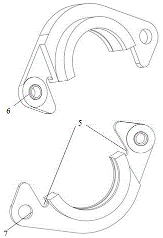
图4 是本发明一种分半式填料压盖分半体示意图。Fig. 4 is a schematic diagram of a half body of a split-half packing gland according to the present invention.
图中:1.上分半体,2.下分半体,3.法兰板结合面,4.中间压环结合面,5.缺口,6.凸止口,7.设置为对应凹止口尺寸的螺栓孔。In the picture: 1. Upper half body, 2. Lower half body, 3. Flange plate joint surface, 4. Middle pressure ring joint surface, 5. Notch, 6. Convex stop, 7. Set to corresponding concave stop size of the bolt holes.
具体实施方式Detailed ways
下面结合附图和具体实施方式对本发明作进一步说明。The present invention will be further described below with reference to the accompanying drawings and specific embodiments.
如图4 所示,分半式填料压盖,包括上分半体1和下分半体2,两分半体的结构相同,这两个分半体通过垂直于轴心线的法兰板结合面3和经过轴心线的中间压环结合面4结合,在中间压环结合面4的两边各有一个缺口5。两分半体各有两个螺栓孔,一个螺栓孔处设置一个较浅的凸止口6,另一个螺栓孔尺寸设置为对应的凹止口尺寸7。As shown in Figure 4, the split-half packing gland includes an upper half body 1 and a
在结合时,两个分半体的缺口5可以使得中间压环结合面4两端没有制作时留下的倒角或倒圆,从而能够完全紧密贴合。在分半体中一个联接螺栓孔处设置一个较浅的凸止口6,而将另一个联接螺栓孔尺寸设置为对应的凹止口尺寸7。在装配时,将其中一个分半体旋转180度,两分半体通过凸凹两止口配合形成一个整体,在拆卸时只需将止口退出即可分开。When combined, the gaps 5 of the two halves can make the two ends of the joint surface 4 of the intermediate pressure ring not have any chamfers or roundings left in the production process, so that they can be completely and tightly fitted. A shallow
Claims (1)
Priority Applications (1)
| Application Number | Priority Date | Filing Date | Title |
|---|---|---|---|
| CN201711401189.5A CN108019515B (en) | 2017-12-22 | 2017-12-22 | A split-half packing gland |
Applications Claiming Priority (1)
| Application Number | Priority Date | Filing Date | Title |
|---|---|---|---|
| CN201711401189.5A CN108019515B (en) | 2017-12-22 | 2017-12-22 | A split-half packing gland |
Publications (2)
| Publication Number | Publication Date |
|---|---|
| CN108019515A CN108019515A (en) | 2018-05-11 |
| CN108019515B true CN108019515B (en) | 2020-07-31 |
Family
ID=62074563
Family Applications (1)
| Application Number | Title | Priority Date | Filing Date |
|---|---|---|---|
| CN201711401189.5A Expired - Fee Related CN108019515B (en) | 2017-12-22 | 2017-12-22 | A split-half packing gland |
Country Status (1)
| Country | Link |
|---|---|
| CN (1) | CN108019515B (en) |
Families Citing this family (1)
| Publication number | Priority date | Publication date | Assignee | Title |
|---|---|---|---|---|
| CN110886719A (en) * | 2018-09-10 | 2020-03-17 | 威乐(中国)水泵系统有限公司 | Horizontal split centrifugal pump shaft seal structure |
Family Cites Families (7)
| Publication number | Priority date | Publication date | Assignee | Title |
|---|---|---|---|---|
| CN1267669C (en) * | 2004-12-17 | 2006-08-02 | 清华大学 | Sealing arrangement of aluminium alloy flange |
| CN201502522U (en) * | 2009-09-09 | 2010-06-09 | 浙江飞旋泵业有限公司 | Split type packing gland |
| CN201526757U (en) * | 2009-09-21 | 2010-07-14 | 上海连成(集团)有限公司 | A p shaped seal groove for sealing a flange |
| CN201739162U (en) * | 2010-07-16 | 2011-02-09 | 湖南湘电长沙水泵有限公司 | Pump split packing gland |
| KR101064254B1 (en) * | 2011-01-31 | 2011-09-14 | (주)하이드로훼스트 | Packing leakage prevention device using hydraulic gland follower |
| CN205896193U (en) * | 2016-08-10 | 2017-01-18 | 山东恒利矿场设备有限公司 | Double -flow -passage cone valve for reciprocating pump |
| CN207648132U (en) * | 2017-12-22 | 2018-07-24 | 江苏大学 | Half formula gland of one kind point |
-
2017
- 2017-12-22 CN CN201711401189.5A patent/CN108019515B/en not_active Expired - Fee Related
Also Published As
| Publication number | Publication date |
|---|---|
| CN108019515A (en) | 2018-05-11 |
Similar Documents
| Publication | Publication Date | Title |
|---|---|---|
| CN205716120U (en) | A kind of assembling pipe joint with Simple sealing circle | |
| CN205781538U (en) | A kind of assembling pipe joint of locking ring | |
| CN207648132U (en) | Half formula gland of one kind point | |
| CN108019515A (en) | Half formula gland of one kind point | |
| CN106762803A (en) | A kind of high-performance petrochemical industry centrifugal pump | |
| CN217206839U (en) | A pump seal | |
| CN205036742U (en) | Quick connector and quick connecting device | |
| CN219840794U (en) | Housing assembly for a motor pump unit and motor pump unit | |
| CN206246650U (en) | For the gear box structure of centrifuge | |
| CN212080141U (en) | Sealing assembly of oil delivery connecting piece of oil pump check valve | |
| CN205716133U (en) | A kind of pipe connecting structure | |
| CN205331424U (en) | Filler structure with adjustable plunger pump is used | |
| CN204386875U (en) | Side plate of high pressure gear pump structure | |
| CN207648131U (en) | Gland | |
| CN204436589U (en) | The bent axle oil pressure coupling of motor | |
| CN208619538U (en) | A high-rigidity double-diaphragm expansion sleeve coupling | |
| CN106195310B (en) | A kind of fixing ball valve | |
| TWM358214U (en) | Structural improvement of oil pressure pump | |
| CN208281670U (en) | A kind of Ifold flange | |
| JP2017025870A (en) | pump | |
| CN221839120U (en) | Pipeline connection structure | |
| CN211009058U (en) | Inlet and outlet improved pump | |
| CN205504000U (en) | Feed -regulating valve | |
| CN205298733U (en) | A can splice valve body for butterfly valve | |
| CN204254086U (en) | The sealing configuration of jointing |
Legal Events
| Date | Code | Title | Description |
|---|---|---|---|
| PB01 | Publication | ||
| PB01 | Publication | ||
| SE01 | Entry into force of request for substantive examination | ||
| SE01 | Entry into force of request for substantive examination | ||
| GR01 | Patent grant | ||
| GR01 | Patent grant | ||
| CF01 | Termination of patent right due to non-payment of annual fee |
Granted publication date: 20200731 |
|
| CF01 | Termination of patent right due to non-payment of annual fee |