CN1080145C - Pulsed plate plasma implantation system - Google Patents
Pulsed plate plasma implantation system Download PDFInfo
- Publication number
- CN1080145C CN1080145C CN97120685A CN97120685A CN1080145C CN 1080145 C CN1080145 C CN 1080145C CN 97120685 A CN97120685 A CN 97120685A CN 97120685 A CN97120685 A CN 97120685A CN 1080145 C CN1080145 C CN 1080145C
- Authority
- CN
- China
- Prior art keywords
- workpiece
- operating cavity
- support plate
- electrically conductive
- chamber
- Prior art date
- Legal status (The legal status is an assumption and is not a legal conclusion. Google has not performed a legal analysis and makes no representation as to the accuracy of the status listed.)
- Expired - Fee Related
Links
Images


Classifications
-
- H—ELECTRICITY
- H01—ELECTRIC ELEMENTS
- H01J—ELECTRIC DISCHARGE TUBES OR DISCHARGE LAMPS
- H01J37/00—Discharge tubes with provision for introducing objects or material to be exposed to the discharge, e.g. for the purpose of examination or processing thereof
- H01J37/32—Gas-filled discharge tubes
- H01J37/32009—Arrangements for generation of plasma specially adapted for examination or treatment of objects, e.g. plasma sources
- H01J37/32412—Plasma immersion ion implantation
-
- C—CHEMISTRY; METALLURGY
- C23—COATING METALLIC MATERIAL; COATING MATERIAL WITH METALLIC MATERIAL; CHEMICAL SURFACE TREATMENT; DIFFUSION TREATMENT OF METALLIC MATERIAL; COATING BY VACUUM EVAPORATION, BY SPUTTERING, BY ION IMPLANTATION OR BY CHEMICAL VAPOUR DEPOSITION, IN GENERAL; INHIBITING CORROSION OF METALLIC MATERIAL OR INCRUSTATION IN GENERAL
- C23C—COATING METALLIC MATERIAL; COATING MATERIAL WITH METALLIC MATERIAL; SURFACE TREATMENT OF METALLIC MATERIAL BY DIFFUSION INTO THE SURFACE, BY CHEMICAL CONVERSION OR SUBSTITUTION; COATING BY VACUUM EVAPORATION, BY SPUTTERING, BY ION IMPLANTATION OR BY CHEMICAL VAPOUR DEPOSITION, IN GENERAL
- C23C14/00—Coating by vacuum evaporation, by sputtering or by ion implantation of the coating forming material
- C23C14/22—Coating by vacuum evaporation, by sputtering or by ion implantation of the coating forming material characterised by the process of coating
- C23C14/48—Ion implantation
Abstract
Method and apparatus for treating a workpiece implantation surface by causing ions to impact the workpiece implantation surface. An implantation chamber defines a chamber interior into which one or more workpieces can be inserted. A support positions one or more workpieces within an interior region of the implantation chamber so that implantation surfaces of the workpieces are facing the interior region. A dopant material in the form of a gas is injected into the implantation chamber to cause the gas to occupy a region of the implantation chamber in close proximity to the one or more workpieces. A plasma of implantation material is created within the interior region of the implantation chamber. First and second conductive electrodes positioned within the implantation chamber include conductive surfaces in proximity to the chamber interior occupied by the one or more workpieces. A voltage source outside the chamber relatively biases the first and second conductive electrodes. A control circuit utilizes the voltage source for repeatedly relatively biasing the first and second conductive electrodes to energize the electrodes with a sequence of pulses that both ionize the gas molecules injected into the chamber and accelerate the ionized gas molecules toward the implantation surfaces of the one or more workpieces.
Description
The present invention relates to a kind of treatment system of workpiece, the workpiece that it will be handled places plasma atmosphere, impacts workpiece with the particle that quickens.A system like this places the plasma atmosphere that includes the band cation with workpiece, then cation is quickened, with the controlled bombardment by ions silicon chip surface of concentration to mix up silicon chip.
The ion source that commercial at present ion implant system uses, it comprises an ion source chamber of separating with implant cavity, can handle one or more workpiece with ionogenic ion in implant cavity.The outlet of ion source chamber is flowed out ion in ion source, then with ion shaping, decomposition, acceleration, form ion beam.Ion beam flow in the ion implant cavity along vacuum material for making clothes beam passage, and ion beam impacts one or more workpiece in this chamber, and workpiece normally is placed on the thin rounded flakes in the implant cavity.It is enough big that the energy of ion beam is wanted, feasible those interior thin slices of ion penetration implant cavity that impact thin slice.When generally using such system, thin slice is a silicon chip, mixes up silicon chip with ion and forms semi-conducting material.To adopt the implanting device of implantation, a kind of like this prior art selectively of mask sheet and formation protective film, can be used to make integrated circuit.
The United States Patent (USP) 4764394 of Conrad, exercise question are " method and apparatus that the plasma source ion is implanted ", disclose a kind of ion implant system with ion collision processing target thing.Form Ionized plasma element around the object in enclosed cavity, just can carry out ion and implant to objective thing surface.In case formed plasma in the zone of surrounding target thing, the ion in the plasma just comes the target assault target thing from all directions, and does not need the manipulation of objects thing.This implantation is that the pulse of adopting high pressure to repeat realizes, normally 20 kilovolts (KV) or higher voltage make the exposed surface of bombardment by ions object.The technology of the manufacturing plasma of being discussed in the United States Patent (USP) 4764394 is that the peripheral region that neutral gas is incorporated into object is made gas ionization in the ionization width of cloth mode of penetrating then.
In the United States Patent (USP) 4764394 disclosed systems of Conrad, set up Ionized plasma with the ion source that separates in the zone around the workpiece, electrode to holding workpieces suitably applies negative voltage pulse then, attracts the positive ion impacts workpiece in the plasma.Structure and method are finished ionization and workpiece processing with a series of energy pulse designed according to this invention.
The present invention handles workpiece with the mode of particle encounter workpiece.Implant cavity is provided with inner chamber.The work mounting s plate of conduction can be used as an electrode, is used for laying the one or more workpiece in the inner chamber.The chamber also comprises the wall of conduction, and this wall surrounds inner chamber.As second electrode.
One or more workpiece are inserted in the implant cavity, are placed on the conductance supporting plate, one or more workpiece are wanted the interior zone of treatment surface facing to implant cavity.The workpiece that will exist with the gas molecule form of band neutral charge is handled material and is injected in the implant cavity, and gas just has been full of by near the implant cavity zone one or more workpiece of conductance supporting plate supporting.
Bias voltage is applied to as between the electrically conductive workpiece support plate of an electrode and the conductive wall as the implant cavity of another electrode.The preferably a series of electric pulses of bias voltage are applied between first electrode and second electrode, make the gas ionization that is injected in the implant cavity, and the charged particle that ionization is produced wants the direction of treatment surface to quicken towards one or more workpiece.
Concrete application of the present invention is that the ion that concentration is controlled is implanted on the silicon chip, mixes up silicon chip.Experience shows, supports by the arm the implant dosage that material can obtain suitable concn with suitable ion.
As can be seen, the present invention is specially adapted to implant flat-panel monitor or similar workpiece, has than the workpiece of high surface area and need handle with ion collision.On flat-panel monitor, form by the substrate of glass or similar material.On one side, scribble polysilicon or amorphous silicon.Substrate after the coating is inserted in the ion implant cavity, handles with ion collision.
Using the present invention has the ion implantation device in the technology that certain advantage is arranged than seeing, and in the prior art, ion source separates with implantation position, links to each other by long vacuum ionic bundle manifold.Owing to saved ion source and its power supply device, the expense of ion implantation device reduces designed according to this invention.Can do lessly because in operating cavity, produce the gaps between electrodes of plasma, so just can reduce the size of operating cavity.Because system dimension, energy consumption is low and attended operation is simple, thereby the cost of use of such implanted device just reduces.For two adjacent plates of making by the suitable material aluminium of silicon (as scribble), because plasma is confined between two plates, so the pollution of implanted device reduces.If workpiece size to be processed strengthens, only need to increase electrode size, so just improved the ability of handling heavy in section workpiece such as flat-panel monitor.The uniformity of implanting is also fine, and fluctuation only has an appointment 1% or littler.
Use disclosed technology to make plasma and be not limited to the ion implantation, disclosed technology also can be used for plasma etching or sand milling.If be applied to the pole reversal of the pulse on first and second electrodes, handle workpiece with regard to available electron, this as handling photoresists, is useful in some cases.In a word, plus or minus voltage can be applied on any one of first or second electrode, and applies reference voltage on another electrode, normally zero potential.
In conjunction with the accompanying drawings a most preferred embodiment of the present invention is elaborated the above-mentioned and other purpose that just the present invention may be better understood, advantage, and feature.
Fig. 1 is the sketch according to the ion implant system of most preferred embodiment design of the present invention;
Fig. 2 A and 2B are the sketches of the amplification of operating cavity, comprise placement negative electrode and anode within it in the operating cavity, are used for producing plasma element;
Fig. 3 is the issuable interactional sketch that impacts between the ion of surface of the work;
Fig. 4 is that ion is implanted the chart of probability as the function of ion energy and quality when the bombardment by ions workpiece;
Fig. 5 is that to use from the gas molecule of boron trifluoride isolated boron be 6 inches thin slice when implanting to diameter, and the ion implant concentration is implanted the chart of the function of thickness down as the thin slice top layer;
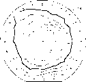
Fig. 6 is a figure, has shown the even end of mixing up when being implanted on 6 inches thin slices with boron.
Fig. 1 is the general illustration of ion implant system 10, and it comprises operating cavity 12, can be inserted in the operating cavity roughly being plane workpiece 14, with these workpiece of ion processing.System shown in Figure 1 comprises charging gate 20, can one at a time single thin slice be inserted in the operating cavity 12.Workpiece is inserted into operating cavity 12 or when from operating cavity 12, taking out, just open and close valve 21, like this, by valve 21, workpiece put into chamber 12 or when from chamber 12, taking out, use charging gate 20 can make operating cavity 12 maintain negative pressure state (with respect to atmospheric pressure).
Be positioned at the top of work plate and what separate with it is gas transmission manifold 32, this manifold is transferred to zone 34 between manifold and the workpiece 14 with ionogenic gas.The zone 34 of workpiece top is the zone that produces plasma in implant system 10 courses of work.The gas molecule that is not ionized and implants flows out from the chamber along outlet 35.In an embodiment shown in Fig. 2 A and 2B, outlet 35 is opened below plate 30.
An injection device that comprises feeder 36, inlet 37 and manifold 32 etc., its feeder 36 that is positioned at outside the chamber 37 enters ionogenic gas from entering the mouth, the chamber wall of flowing through enters into manifold, many branch roads are arranged in the manifold, and these branch roads are from 37 row of openings 40 (Fig. 2 A and 2B) of leading to over against workpiece that enter the mouth.If the gas density between maintenance manifold and the workpiece 14 in the zone 34 is even as far as possible, handle just evenly.The manifold 32 recommended is planar rondure normally, comprises a row of openings 40, can make around the gas concentration of manifold periphery uniformity as much as possible.Like this, workpiece 14 is placed on the plate 30, is placed on the inside of roughly rounded plate 30, to avoid the inhomogeneous district of plasma.Reasonably design as the plate 30 of first electrode and as the edge shape of the manifold 32 of second electrode, intensity that just can the control electrode fringe field, thus guarantee to implant evenly.
(Fig. 2 A) applies a series of negative voltage pulse to conductive plate 30, and make manifold 32 keep zero potential, like this, in case gas enters into plasma slab 34, under the negative voltage pulse effect, gas molecule ionization (losing one or more electronics), and positively charged atom is quickened towards workpiece.In some cases, be applied on the plate 30 and manifold 32 on polarity of voltage can make the electron bombardment workpiece of acceleration conversely.In disclosed embodiment, illustrated single workpiece to be placed on the situation on the plate 30, still, also can implant a plurality of workpiece simultaneously with the present invention.
Fig. 2 A shows with four different pressue devices with 2B, makes to form certain density workpiece in the zone 34 of workpiece 14 tops and handle material.Among Fig. 2 A, manifold 32 and chamber wall ground connection.In this structure, negative voltage pulse N is applied on the conductance supporting plate 30, feasible zone 34 ionization under the high voltage effect, and ion is quickened to the plate direction.In the embodiment of Fig. 2 B, support plate 30 ground connection, potential pulse is applied on the manifold 32.In this structure, positive voltage pulse P makes positively charged ion quicken to workpiece 14 directions.
The modulation circuit of recommending 100 comprises the power supply by high-octane curing switch control, this power supply can provide series of pulses 112, not only makes the gas molecule ionization that is injected in the chamber but also makes the ionized gas molecule quicken to the implant surface of one or more workpiece 14.The repetition rate of strobe pulse 112 and pulse spacing under the impulse action on two electrodes 30,32, guarantee to produce glow discharge in the zone 34, form plasma and keep ionization.After ionization pulse is removed, because combination and diffusion again, after a period of time (order of magnitude be a millisecond), the plasma density reduction.In order to keep the existence of plasma constantly, pulse frequency must be at thousands of times of per second or higher.But, under low pulse frequency, in each pulse process, also can produce ionization and implantation, it is lower only to implant frequency.
Pollute for reducing, in one embodiment, plate 30 and manifold 32 usefulness scribble the aluminium of silicon and make.To small part chamber wall 22 and/or on the inoperative zone of plate 30 the appropriate insulation material is arranged, as quartz, this also helps to reduce pollution and energy consumption.
Fig. 3 has illustrated when the ion 130 from plasma zone 34 impacts the treatment surface 120 of workpiece 14, contingent interaction on surface 120.As shown in Figure 3, possible interaction has produced non-resilient (producing photon, X ray, inferior electronics and ion implantation) and elastic reaction (particle of sputter and reflection) between ion-surface.Incident ion 130 can be captured in the solid lattice of workpiece 14, and Here it is, and ion is implanted.Catch probability n and be shown in the chart of Fig. 4, it is along with the minimizing of the increase of ion energy E and mass of ion m and increase.Under high-energy (E>10KeV), right of prize rate n=1, irrelevant with mass of ion.Mainly by the plate voltage decision of plasma, the pulse voltage that provides in the modulator 100 is provided again plate voltage ion energy.Pounce on and obtain the influence that probability also is subjected to gas pressure, this is because before ion arrives surface 120 because and gas molecule collision, ion can lose portion of energy.
Use charging gate 20 that workpiece 14 is inserted in the chamber, can make the inner chamber in chamber 12 when implanting, be in vacuum state.Vacuum pump 140 makes inner chamber be in negative pressure, regulates negative pressure by the valve 142 that is installed between chamber 12 and the pump 140.Same pump 140 also can be connected on the gas vent 35.
Can in silicon chip, mix up the nitrogen dopant material according to the present invention.Nitrogen is sent in the chamber 12 through aluminium manifold 32 from source of the gas 36, and manifold 32 transmits nitrogen by a plurality of passages that extend in manifold 32.These a plurality of passages outwards lead in the inner chamber.Whole chamber 12 shown in Fig. 2 A all is ground connection except sheet support plate 30, and sheet support plate 30 is supporting by charging gate 20 and is being inserted into silicon chip in the chamber.In order to make supporting root 30 be subjected to impulse action, insulator 150 separates chamber wall and support plate 30.The sidewall in chamber and base plate have the quartz components protection.Applying negative voltage pulse on sheet support plate 30, is that 5 milliseconds, pulse frequency are 2000 pulses of per second (PPS) as pulse duration, will produce nitrogen plasma.
The threshold value pulse voltage of carrying out glow discharge depends on the gas type that is incorporated in the chamber 12, gas pressure, and the distance of electrode 30,32, under the potential pulse of certain amplitude, the distance of electrode has determined the intensity of electric field.
Set up the required pulse voltage of ionization that needs and also be subjected to other outside influences of importing in zone 34.Shown in Fig. 2 A and Fig. 2 B, these inputs comprise radiation source 152, and it can be by window 153 irradiation ultraviolet radiations or other suitable rays of chamber wall.Also can near zone 34, place Helmholtz coil 154, set up suitable magnetic field at regional 34 places.Coil 154 can be placed on the inside or the outside in chamber 12, adjacent domain 34.In another embodiment, can in zone 34, set up magnetic field with permanent magnet.
Can show there is not magnetic field by experience of the present invention, in the chamber, produce plasma need apply-voltage of 3.6KV corresponding to chamber wall zero potential.Under identical electrode distance, and 40 Gausses' that Helmholtz coil 154 produces magnetic field is arranged, just can under lower voltage-1.8KV, produce plasma.Radiological dose is relevant with gas pressure and impulsive condition.In pulse duration is 4 milliseconds, and pulse frequency is 5000Hz, and voltage is under the implantation condition of V=-5KV, and corresponding to different gas pressures, radiological dose can be from 4 * 10
13Square centimeter/second (cm
2/ sec) to 2 * 10
15Square centimeter/second (cm
2/ sec).
Be to mix up on 6 inches the silicon chip at diameter with the present invention, uniformity is fine.Fig. 5 illustrated to be used in boron trifluoride under the impulse action carry out the anode plasma when implanting boron mix up curve (every cubic centimetre atomic concentration is the function apart from the sheet surface distance).Fig. 6 mixes up inhomogeneity schematic diagram, and it is to mix up 6 inches silicon chip with boron, and annealing rapidly subsequently obtains.The schematic diagram of Fig. 6 is the figure of the plate resistance that measures with 4 point probes, and it is similar to topographic map.What illustrate among Fig. 6 is to wait the plate resistive conductor, rather than contour.Average plate resistance is represented with solid line.Inside and outside roughly concentric line is illustrated on the mean value and the plate resistance value of following step-feeding from this solid line along radial direction.On the surface of thin slice 14, from the total deviation of plate resistance median or average plate resistance about 1%.
Although the present invention is described with certain special case,, in the essence of appended claim or scope to all modifications and the replacement of disclosed design, all within the scope of the present invention.
Claims (21)
1. method of handling one or more workpiece, it may further comprise the steps:
(a) one or more workpiece (14) are inserted in the inner chamber (24) of an operating cavity (12), described one or more workpiece (14) at an electrically conductive workpiece support plate (30) upper support, and the treatment surface (120) that makes described one or more workpiece (14) is facing to the treatment region (34) in the described inner chamber (24) of described operating cavity (12), and described operating cavity (12) has the conductive wall (22) that surrounds its inner chamber (24);
(b) will handle material with the workpiece of the gas molecule of neutral charge and be injected in the described operating cavity (12), like this, described gas molecule just has been full of described operating space (34);
(c) between the described conductive wall (22) of described electrically conductive workpiece support plate (30) and described operating cavity (12), apply bias voltage, make the gas ionization that is injected in the operating cavity (12), and make Ionized charged particle quicken the treatment surface (120) of impacting described one or more workpiece (14).
2. method according to claim 1, it is characterized in that: wherein, the described step (c) that applies bias voltage comprises that the described conductive wall (22) corresponding to described operating cavity (12) applies back bias voltage on described electrically conductive workpiece support plate (30), make and be injected into the interior gas molecule ionization of described operating cavity (12), the positively charged ion that produces is quickened the treatment surface (120) of impacting described one or more workpiece (14).
3. method according to claim 1, it is characterized in that: wherein, the described step (c) that applies bias voltage comprises that the described conductive wall (22) corresponding to described operating cavity (12) applies positive bias on described electrically conductive workpiece support plate (30), make and be injected into the interior gas molecule ionization of described operating cavity (12), the electronics that produces is quickened the treatment surface (120) of impacting described one or more workpiece (14).
4. method according to claim 1, it is characterized in that: wherein, the described step (c) that applies bias voltage comprise with a series of potential pulses (112, N) be applied on the described electrically conductive workpiece support plate (30), keep being with on the described conductive wall (22) zero potential simultaneously.
5. method according to claim 1, it is characterized in that: wherein, the described step (c) that applies bias voltage comprises a series of potential pulses (P) is applied on the described conductive wall (22), keeps being with on the described electrically conductive workpiece support plate (30) zero potential simultaneously.
6. method according to claim 1 is characterized in that: it also is included in the described processing region (34) of described operating cavity (12) and adds magnetic field.
7. method according to claim 1 is characterized in that: it also is included in the described processing region (34) of described operating cavity (12) and applies ray.
8. method according to claim 1, it is characterized in that: wherein, the potential pulse that is applied on described electrically conductive workpiece support plate (30) and the described conductive wall (22) has enough pulse frequencies, width, amplitude, makes the level that described inner chamber (24) the ionic medium bulk concentration of described operating cavity (12) keeps relative stability.
9. method according to claim 8 is characterized in that: wherein, described potential pulse (112, N, P) repetition rate of pulse is at the order of magnitude of KHz at the order of magnitude of millisecond the cycle.
10. device of handling one or more workpiece (14), it comprises:
(a) operating cavity (12), described operating cavity have inner chamber (24) and the conductive wall (22) of encirclement inner chamber (24) are arranged;
(b) an electrically conductive workpiece support plate (30), described electrically conductive workpiece support plate are used for supporting the one or more workpiece (14) in the described inner chamber (24) of described operating cavity (12);
(c) injection device (32) will be injected into by the processing material that gas molecule is formed in the described operating cavity (12), and like this, gas molecule just has been full of near the processing region (34) the one or more workpiece (14) that supported by the support plate (30) that conducts electricity; It is characterized in that:
(d) control circuit (100), described control circuit is used for applying bias voltage on the conductive wall (22) of the work mounting s plate (30) of described conduction and described operating cavity (12), described control circuit (100) comprises provides a series of potential pulses (112, N, P) power supply, make to be injected into the interior gas molecule ionization of described operating cavity (12), and the charged ion that produces is quickened the treatment surface (120) of impacting described one or more workpiece (14).
11. device according to claim 10 is characterized in that: wherein, described conductive wall (22) comprises injection device (32).
12. device according to claim 10, it is characterized in that: wherein, described control circuit (100) described repeatedly in operating cavity (12) described conductive wall (22) and described conduction work support plate (30) between apply back bias voltage, the feasible gas molecule ionization that is injected into described operating cavity (12), and the ion of the feasible positively charged that produces quickens the treatment surface (120) of impacting described one or more workpiece (14).
13. device according to claim 10, it is characterized in that: wherein, described control circuit (100) applies positive bias repeatedly between the described conductive wall (22) of described operating cavity (12) and described electrically conductive workpiece support plate (30), the feasible gas molecule ionization that is injected into described operating cavity (12), and make the electronics that produces quicken the treatment surface (120) of impacting one or more workpiece (14).
14. device according to claim 10, it is characterized in that: wherein, described power supply with described potential pulse (112, N) be applied on the described electrically conductive workpiece support plate (30), described control circuit (100) makes and keeps a zero potential on the described conductive wall (22).
15. device according to claim 10, it is characterized in that: wherein, described power supply is applied to described potential pulse (P) on the described conductive wall (22), and described control circuit (100) makes and keeps a zero potential on the described electrically conductive workpiece support plate (30).
16. device according to claim 10 is characterized in that: wherein, described electrically conductive workpiece support plate (30) is being supported by the insulated part (150) of described operating cavity (12).
17. device according to claim 10 is characterized in that: wherein, described injection device (32) comprises gas molecule is sent to manifold (32) in the described inner chamber (24).
18. device according to claim 17, it is characterized in that: wherein, described manifold (32) comprises electric conducting material, and described manifold (32) is being supported by the insulated part (150) of described operating cavity (12), described potential pulse (P) is applied on the described manifold (32) of conduction with described power supply, between conduction few described manifold (32) and described electrically conductive workpiece support plate (30), applies bias voltage.
19. device according to claim 10 is characterized in that: wherein the nonclient area to described inner chamber of small part (24) and described electrically conductive workpiece support plate (30) links to each other with the material of insulation.
20. device according to claim 10 is characterized in that: it also comprises a magnet (154), and described magnet (154) is set up a magnetic field at the described processing region (34) of described operating cavity (12).
21. device according to claim 10 is characterized in that: it also comprises a radiation source (152), and described radiation source (152) carries out radiation to the described processing region (34) of described operating cavity (12).
Applications Claiming Priority (4)
| Application Number | Priority Date | Filing Date | Title |
|---|---|---|---|
| US728,000 | 1996-10-10 | ||
| US08/728,000 US5654043A (en) | 1996-10-10 | 1996-10-10 | Pulsed plate plasma implantation system and method |
| US728000 | 1996-10-10 | ||
| CA002225063A CA2225063A1 (en) | 1996-10-10 | 1998-01-27 | Pulsed plate plasma implantation system |
Publications (2)
| Publication Number | Publication Date |
|---|---|
| CN1193555A CN1193555A (en) | 1998-09-23 |
| CN1080145C true CN1080145C (en) | 2002-03-06 |
Family
ID=31716438
Family Applications (1)
| Application Number | Title | Priority Date | Filing Date |
|---|---|---|---|
| CN97120685A Expired - Fee Related CN1080145C (en) | 1996-10-10 | 1997-10-09 | Pulsed plate plasma implantation system |
Country Status (5)
| Country | Link |
|---|---|
| US (1) | US5654043A (en) |
| EP (1) | EP0838840B1 (en) |
| JP (1) | JP4178330B2 (en) |
| CN (1) | CN1080145C (en) |
| CA (1) | CA2225063A1 (en) |
Cited By (2)
| Publication number | Priority date | Publication date | Assignee | Title |
|---|---|---|---|---|
| CN1320605C (en) * | 2003-07-03 | 2007-06-06 | 松下电器产业株式会社 | Method and device for plasma doping |
| CN100471412C (en) * | 1999-04-13 | 2009-03-25 | 3M创新有限公司 | Mechanical fastener |
Families Citing this family (81)
| Publication number | Priority date | Publication date | Assignee | Title |
|---|---|---|---|---|
| US5653811A (en) | 1995-07-19 | 1997-08-05 | Chan; Chung | System for the plasma treatment of large area substrates |
| US5968377A (en) * | 1996-05-24 | 1999-10-19 | Sekisui Chemical Co., Ltd. | Treatment method in glow-discharge plasma and apparatus thereof |
| US5654043A (en) * | 1996-10-10 | 1997-08-05 | Eaton Corporation | Pulsed plate plasma implantation system and method |
| DE19702294A1 (en) * | 1997-01-23 | 1998-07-30 | Rossendorf Forschzent | Modulator for plasma immersion ion implantation |
| US6572933B1 (en) | 1997-09-24 | 2003-06-03 | The Regents Of The University Of California | Forming adherent coatings using plasma processing |
| JP4588213B2 (en) * | 1997-12-15 | 2010-11-24 | フオルクスワーゲン・アクチエンゲゼルシヤフト | Plasma boriding treatment |
| JP3027968B2 (en) * | 1998-01-29 | 2000-04-04 | 日新電機株式会社 | Film forming equipment |
| US6217724B1 (en) * | 1998-02-11 | 2001-04-17 | Silicon General Corporation | Coated platen design for plasma immersion ion implantation |
| US6274459B1 (en) | 1998-02-17 | 2001-08-14 | Silicon Genesis Corporation | Method for non mass selected ion implant profile control |
| US6101971A (en) * | 1998-05-13 | 2000-08-15 | Axcelis Technologies, Inc. | Ion implantation control using charge collection, optical emission spectroscopy and mass analysis |
| US6300643B1 (en) * | 1998-08-03 | 2001-10-09 | Varian Semiconductor Equipment Associates, Inc. | Dose monitor for plasma doping system |
| US6020592A (en) * | 1998-08-03 | 2000-02-01 | Varian Semiconductor Equipment Associates, Inc. | Dose monitor for plasma doping system |
| US6050218A (en) * | 1998-09-28 | 2000-04-18 | Eaton Corporation | Dosimetry cup charge collection in plasma immersion ion implantation |
| US6458723B1 (en) | 1999-06-24 | 2002-10-01 | Silicon Genesis Corporation | High temperature implant apparatus |
| KR20020019596A (en) * | 1999-08-06 | 2002-03-12 | 브라이언 알. 바흐맨 | System and method for providing implant dose uniformity across the surface of a substrate |
| US6237527B1 (en) | 1999-08-06 | 2001-05-29 | Axcelis Technologies, Inc. | System for improving energy purity and implant consistency, and for minimizing charge accumulation of an implanted substrate |
| US6504159B1 (en) | 1999-09-14 | 2003-01-07 | International Business Machines Corporation | SOI plasma source ion implantation |
| US6335536B1 (en) | 1999-10-27 | 2002-01-01 | Varian Semiconductor Equipment Associates, Inc. | Method and apparatus for low voltage plasma doping using dual pulses |
| US6182604B1 (en) | 1999-10-27 | 2001-02-06 | Varian Semiconductor Equipment Associates, Inc. | Hollow cathode for plasma doping system |
| US6458430B1 (en) * | 1999-12-22 | 2002-10-01 | Axcelis Technologies, Inc. | Pretreatment process for plasma immersion ion implantation |
| JP4334723B2 (en) * | 2000-03-21 | 2009-09-30 | 新明和工業株式会社 | Ion plating film forming apparatus and ion plating film forming method. |
| US6305316B1 (en) | 2000-07-20 | 2001-10-23 | Axcelis Technologies, Inc. | Integrated power oscillator RF source of plasma immersion ion implantation system |
| US7223676B2 (en) | 2002-06-05 | 2007-05-29 | Applied Materials, Inc. | Very low temperature CVD process with independently variable conformality, stress and composition of the CVD layer |
| US6893907B2 (en) | 2002-06-05 | 2005-05-17 | Applied Materials, Inc. | Fabrication of silicon-on-insulator structure using plasma immersion ion implantation |
| US6939434B2 (en) | 2000-08-11 | 2005-09-06 | Applied Materials, Inc. | Externally excited torroidal plasma source with magnetic control of ion distribution |
| US7294563B2 (en) | 2000-08-10 | 2007-11-13 | Applied Materials, Inc. | Semiconductor on insulator vertical transistor fabrication and doping process |
| US7166524B2 (en) * | 2000-08-11 | 2007-01-23 | Applied Materials, Inc. | Method for ion implanting insulator material to reduce dielectric constant |
| US7430984B2 (en) * | 2000-08-11 | 2008-10-07 | Applied Materials, Inc. | Method to drive spatially separate resonant structure with spatially distinct plasma secondaries using a single generator and switching elements |
| US7320734B2 (en) * | 2000-08-11 | 2008-01-22 | Applied Materials, Inc. | Plasma immersion ion implantation system including a plasma source having low dissociation and low minimum plasma voltage |
| US7137354B2 (en) * | 2000-08-11 | 2006-11-21 | Applied Materials, Inc. | Plasma immersion ion implantation apparatus including a plasma source having low dissociation and low minimum plasma voltage |
| US7479456B2 (en) | 2004-08-26 | 2009-01-20 | Applied Materials, Inc. | Gasless high voltage high contact force wafer contact-cooling electrostatic chuck |
| US7037813B2 (en) * | 2000-08-11 | 2006-05-02 | Applied Materials, Inc. | Plasma immersion ion implantation process using a capacitively coupled plasma source having low dissociation and low minimum plasma voltage |
| US7288491B2 (en) | 2000-08-11 | 2007-10-30 | Applied Materials, Inc. | Plasma immersion ion implantation process |
| US7094670B2 (en) | 2000-08-11 | 2006-08-22 | Applied Materials, Inc. | Plasma immersion ion implantation process |
| US7303982B2 (en) * | 2000-08-11 | 2007-12-04 | Applied Materials, Inc. | Plasma immersion ion implantation process using an inductively coupled plasma source having low dissociation and low minimum plasma voltage |
| US7465478B2 (en) | 2000-08-11 | 2008-12-16 | Applied Materials, Inc. | Plasma immersion ion implantation process |
| US7094316B1 (en) | 2000-08-11 | 2006-08-22 | Applied Materials, Inc. | Externally excited torroidal plasma source |
| US7183177B2 (en) * | 2000-08-11 | 2007-02-27 | Applied Materials, Inc. | Silicon-on-insulator wafer transfer method using surface activation plasma immersion ion implantation for wafer-to-wafer adhesion enhancement |
| WO2002023594A2 (en) * | 2000-09-15 | 2002-03-21 | Mattson Thermal Products Gmbh | Apparatus and method for reducing contamination on thermally processed semiconductor substrates |
| US7309997B1 (en) | 2000-09-15 | 2007-12-18 | Varian Semiconductor Equipment Associates, Inc. | Monitor system and method for semiconductor processes |
| AU2001282327A1 (en) * | 2000-09-18 | 2002-04-02 | Axcelis Technologies, Inc. | System and method for controlling sputtering and deposition effects in a plasma immersion implantation device |
| US20040016402A1 (en) * | 2002-07-26 | 2004-01-29 | Walther Steven R. | Methods and apparatus for monitoring plasma parameters in plasma doping systems |
| US7263991B2 (en) * | 2002-10-01 | 2007-09-04 | Weber-Stephen Products Co. | Outdoor gas fireplace |
| US20050027028A1 (en) * | 2003-07-31 | 2005-02-03 | Kelly Stephen M. | Polymer networks, methods of fabricating and devices |
| US7695590B2 (en) | 2004-03-26 | 2010-04-13 | Applied Materials, Inc. | Chemical vapor deposition plasma reactor having plural ion shower grids |
| US7291360B2 (en) | 2004-03-26 | 2007-11-06 | Applied Materials, Inc. | Chemical vapor deposition plasma process using plural ion shower grids |
| US7244474B2 (en) | 2004-03-26 | 2007-07-17 | Applied Materials, Inc. | Chemical vapor deposition plasma process using an ion shower grid |
| US20050211547A1 (en) * | 2004-03-26 | 2005-09-29 | Applied Materials, Inc. | Reactive sputter deposition plasma reactor and process using plural ion shower grids |
| US20050260354A1 (en) * | 2004-05-20 | 2005-11-24 | Varian Semiconductor Equipment Associates, Inc. | In-situ process chamber preparation methods for plasma ion implantation systems |
| US7878145B2 (en) * | 2004-06-02 | 2011-02-01 | Varian Semiconductor Equipment Associates, Inc. | Monitoring plasma ion implantation systems for fault detection and process control |
| US20050287307A1 (en) * | 2004-06-23 | 2005-12-29 | Varian Semiconductor Equipment Associates, Inc. | Etch and deposition control for plasma implantation |
| US7741621B2 (en) * | 2004-07-14 | 2010-06-22 | City University Of Hong Kong | Apparatus and method for focused electric field enhanced plasma-based ion implantation |
| US7767561B2 (en) | 2004-07-20 | 2010-08-03 | Applied Materials, Inc. | Plasma immersion ion implantation reactor having an ion shower grid |
| US8058156B2 (en) | 2004-07-20 | 2011-11-15 | Applied Materials, Inc. | Plasma immersion ion implantation reactor having multiple ion shower grids |
| US20060043531A1 (en) * | 2004-08-27 | 2006-03-02 | Varian Semiconductor Equipment Associates, Inc. | Reduction of source and drain parasitic capacitance in CMOS devices |
| US7666464B2 (en) * | 2004-10-23 | 2010-02-23 | Applied Materials, Inc. | RF measurement feedback control and diagnostics for a plasma immersion ion implantation reactor |
| US7428915B2 (en) * | 2005-04-26 | 2008-09-30 | Applied Materials, Inc. | O-ringless tandem throttle valve for a plasma reactor chamber |
| US7422775B2 (en) * | 2005-05-17 | 2008-09-09 | Applied Materials, Inc. | Process for low temperature plasma deposition of an optical absorption layer and high speed optical annealing |
| US7109098B1 (en) | 2005-05-17 | 2006-09-19 | Applied Materials, Inc. | Semiconductor junction formation process including low temperature plasma deposition of an optical absorption layer and high speed optical annealing |
| US7312162B2 (en) * | 2005-05-17 | 2007-12-25 | Applied Materials, Inc. | Low temperature plasma deposition process for carbon layer deposition |
| US20060260545A1 (en) * | 2005-05-17 | 2006-11-23 | Kartik Ramaswamy | Low temperature absorption layer deposition and high speed optical annealing system |
| US7312148B2 (en) * | 2005-08-08 | 2007-12-25 | Applied Materials, Inc. | Copper barrier reflow process employing high speed optical annealing |
| US7323401B2 (en) * | 2005-08-08 | 2008-01-29 | Applied Materials, Inc. | Semiconductor substrate process using a low temperature deposited carbon-containing hard mask |
| US7429532B2 (en) * | 2005-08-08 | 2008-09-30 | Applied Materials, Inc. | Semiconductor substrate process using an optically writable carbon-containing mask |
| US7335611B2 (en) * | 2005-08-08 | 2008-02-26 | Applied Materials, Inc. | Copper conductor annealing process employing high speed optical annealing with a low temperature-deposited optical absorber layer |
| US8642135B2 (en) | 2005-09-01 | 2014-02-04 | Micron Technology, Inc. | Systems and methods for plasma doping microfeature workpieces |
| KR100635786B1 (en) * | 2005-10-05 | 2006-10-18 | 삼성전자주식회사 | Method of plasma doping a substrate with ions and apparatus for plasma doping a substrate using the same |
| WO2008041702A1 (en) * | 2006-10-03 | 2008-04-10 | Panasonic Corporation | Plasma doping method and apparatus |
| KR20090106617A (en) * | 2007-01-19 | 2009-10-09 | 어플라이드 머티어리얼스, 인코포레이티드 | Plasma immersion chamber |
| DE102008028542B4 (en) * | 2008-06-16 | 2012-07-12 | Fraunhofer-Gesellschaft zur Förderung der angewandten Forschung e.V. | Method and apparatus for depositing a layer on a substrate by means of a plasma-enhanced chemical reaction |
| CN101922046B (en) * | 2010-09-01 | 2012-07-04 | 中国科学院微电子研究所 | Plasma immersion implantation device |
| US10128090B2 (en) | 2012-02-22 | 2018-11-13 | Lam Research Corporation | RF impedance model based fault detection |
| US9114666B2 (en) | 2012-02-22 | 2015-08-25 | Lam Research Corporation | Methods and apparatus for controlling plasma in a plasma processing system |
| US9197196B2 (en) | 2012-02-22 | 2015-11-24 | Lam Research Corporation | State-based adjustment of power and frequency |
| US10157729B2 (en) | 2012-02-22 | 2018-12-18 | Lam Research Corporation | Soft pulsing |
| US9462672B2 (en) | 2012-02-22 | 2016-10-04 | Lam Research Corporation | Adjustment of power and frequency based on three or more states |
| US9842725B2 (en) | 2013-01-31 | 2017-12-12 | Lam Research Corporation | Using modeling to determine ion energy associated with a plasma system |
| US9594105B2 (en) | 2014-01-10 | 2017-03-14 | Lam Research Corporation | Cable power loss determination for virtual metrology |
| US10950421B2 (en) | 2014-04-21 | 2021-03-16 | Lam Research Corporation | Using modeling for identifying a location of a fault in an RF transmission system for a plasma system |
| KR102145205B1 (en) * | 2014-04-25 | 2020-08-19 | 삼성전자주식회사 | Method of manufaucturing semiconductor device and method of maintaining deposition apparatus |
| US9761459B2 (en) | 2015-08-05 | 2017-09-12 | Lam Research Corporation | Systems and methods for reverse pulsing |
Citations (3)
| Publication number | Priority date | Publication date | Assignee | Title |
|---|---|---|---|---|
| US4764394A (en) * | 1987-01-20 | 1988-08-16 | Wisconsin Alumni Research Foundation | Method and apparatus for plasma source ion implantation |
| EP0296496A2 (en) * | 1987-06-23 | 1988-12-28 | Design Technology Corporation | Method and apparatus for automatic handling and preparation of sandwiches |
| US5354381A (en) * | 1993-05-07 | 1994-10-11 | Varian Associates, Inc. | Plasma immersion ion implantation (PI3) apparatus |
Family Cites Families (6)
| Publication number | Priority date | Publication date | Assignee | Title |
|---|---|---|---|---|
| DE3118785A1 (en) * | 1981-05-12 | 1982-12-02 | Siemens AG, 1000 Berlin und 8000 München | METHOD AND DEVICE FOR DOPING SEMICONDUCTOR MATERIAL |
| WO1993018201A1 (en) * | 1992-03-02 | 1993-09-16 | Varian Associates, Inc. | Plasma implantation process and equipment |
| US5330800A (en) * | 1992-11-04 | 1994-07-19 | Hughes Aircraft Company | High impedance plasma ion implantation method and apparatus |
| US5289010A (en) * | 1992-12-08 | 1994-02-22 | Wisconsin Alumni Research Foundation | Ion purification for plasma ion implantation |
| US5558718A (en) * | 1994-04-08 | 1996-09-24 | The Regents, University Of California | Pulsed source ion implantation apparatus and method |
| US5654043A (en) * | 1996-10-10 | 1997-08-05 | Eaton Corporation | Pulsed plate plasma implantation system and method |
-
1996
- 1996-10-10 US US08/728,000 patent/US5654043A/en not_active Expired - Lifetime
-
1997
- 1997-10-07 EP EP97307902A patent/EP0838840B1/en not_active Expired - Lifetime
- 1997-10-09 CN CN97120685A patent/CN1080145C/en not_active Expired - Fee Related
- 1997-10-13 JP JP27856497A patent/JP4178330B2/en not_active Expired - Fee Related
-
1998
- 1998-01-27 CA CA002225063A patent/CA2225063A1/en not_active Abandoned
Patent Citations (3)
| Publication number | Priority date | Publication date | Assignee | Title |
|---|---|---|---|---|
| US4764394A (en) * | 1987-01-20 | 1988-08-16 | Wisconsin Alumni Research Foundation | Method and apparatus for plasma source ion implantation |
| EP0296496A2 (en) * | 1987-06-23 | 1988-12-28 | Design Technology Corporation | Method and apparatus for automatic handling and preparation of sandwiches |
| US5354381A (en) * | 1993-05-07 | 1994-10-11 | Varian Associates, Inc. | Plasma immersion ion implantation (PI3) apparatus |
Cited By (2)
| Publication number | Priority date | Publication date | Assignee | Title |
|---|---|---|---|---|
| CN100471412C (en) * | 1999-04-13 | 2009-03-25 | 3M创新有限公司 | Mechanical fastener |
| CN1320605C (en) * | 2003-07-03 | 2007-06-06 | 松下电器产业株式会社 | Method and device for plasma doping |
Also Published As
| Publication number | Publication date |
|---|---|
| CA2225063A1 (en) | 1999-07-27 |
| US5654043A (en) | 1997-08-05 |
| CN1193555A (en) | 1998-09-23 |
| EP0838840B1 (en) | 2006-05-31 |
| EP0838840A2 (en) | 1998-04-29 |
| JPH10121240A (en) | 1998-05-12 |
| JP4178330B2 (en) | 2008-11-12 |
| EP0838840A3 (en) | 1999-06-23 |
Similar Documents
| Publication | Publication Date | Title |
|---|---|---|
| CN1080145C (en) | Pulsed plate plasma implantation system | |
| US5911832A (en) | Plasma immersion implantation with pulsed anode | |
| US6050218A (en) | Dosimetry cup charge collection in plasma immersion ion implantation | |
| EP0507885B1 (en) | A low frequency inductive rf plasma reactor | |
| JP2501770B2 (en) | Method of plasma treating an article | |
| KR100559197B1 (en) | Pretreatment process for plasma immersion ion implantation | |
| KR100395272B1 (en) | Apparatus for obtaining does uniformity in plasma doping ion implantation processes | |
| KR100517300B1 (en) | Ion implantation control using charge collection, optical emission spectroscopy and mass analysis | |
| JP4073174B2 (en) | Neutral particle beam processing equipment | |
| US5637180A (en) | Plasma processing method and plasma generator | |
| JP2001500322A (en) | Apparatus and method for uniform, less damaging and anisotropic processing | |
| EP1204985A1 (en) | Implanting system and method | |
| US8329055B2 (en) | Plasma uniformity control using biased array | |
| US20070069157A1 (en) | Methods and apparatus for plasma implantation with improved dopant profile | |
| JP2000068227A (en) | Method for processing surface and device thereof | |
| KR20020020010A (en) | Method for Surface Modification of 3-Dimensional Bulk Polymers | |
| EP0044372B1 (en) | Fabrication and use of a high aspect ratio, high resolution collimating mask for ion beam growth of semiconductor devices | |
| JPH08165563A (en) | Electron-beam annealing device | |
| Liu et al. | Self-neutralized ion implantation into insulators | |
| KR19980032745A (en) | Pulse Plate Plasma Ion Implantation System | |
| JPH01152721A (en) | Doping with impurity | |
| JPH01243359A (en) | Plasma doping | |
| Quick | Electron beam neutralization of large aspect ratio features during plasma etching | |
| JPH03102755A (en) | Ion implanting method | |
| JPS63200456A (en) | Ion implantation device |
Legal Events
| Date | Code | Title | Description |
|---|---|---|---|
| C06 | Publication | ||
| PB01 | Publication | ||
| C10 | Entry into substantive examination | ||
| SE01 | Entry into force of request for substantive examination | ||
| C53 | Correction of patent of invention or patent application | ||
| COR | Change of bibliographic data |
Free format text: CORRECT: APPLICANT; FROM: EATON CORP. TO: AXCELIS TECH INC. |
|
| CP03 | Change of name, title or address |
Address after: Massachusetts, USA Applicant after: Esselis Technologies Co. Address before: ohio Applicant before: Eaton Corp. |
|
| C14 | Grant of patent or utility model | ||
| GR01 | Patent grant | ||
| C17 | Cessation of patent right | ||
| CF01 | Termination of patent right due to non-payment of annual fee |
Granted publication date: 20020306 Termination date: 20091109 |