CN107902707B - Integrated waterway plate and water purifier - Google Patents

Integrated waterway plate and water purifier Download PDF

Info

Publication number
CN107902707B
CN107902707B CN201711169164.7A CN201711169164A CN107902707B CN 107902707 B CN107902707 B CN 107902707B CN 201711169164 A CN201711169164 A CN 201711169164A CN 107902707 B CN107902707 B CN 107902707B
Authority
CN
China
Prior art keywords
water
channel
straight
flow passage
inner end
Prior art date
Legal status (The legal status is an assumption and is not a legal conclusion. Google has not performed a legal analysis and makes no representation as to the accuracy of the status listed.)
Active
Application number
CN201711169164.7A
Other languages
Chinese (zh)
Other versions
CN107902707A (en
Inventor
徐广飞
蔡雪刚
郑跃东
Current Assignee (The listed assignees may be inaccurate. Google has not performed a legal analysis and makes no representation or warranty as to the accuracy of the list.)
Midea Group Co Ltd
Foshan Shunde Midea Water Dispenser Manufacturing Co Ltd
Original Assignee
Midea Group Co Ltd
Foshan Shunde Midea Water Dispenser Manufacturing Co Ltd
Priority date (The priority date is an assumption and is not a legal conclusion. Google has not performed a legal analysis and makes no representation as to the accuracy of the date listed.)
Filing date
Publication date
Application filed by Midea Group Co Ltd, Foshan Shunde Midea Water Dispenser Manufacturing Co Ltd filed Critical Midea Group Co Ltd
Priority to CN201711169164.7A priority Critical patent/CN107902707B/en
Publication of CN107902707A publication Critical patent/CN107902707A/en
Application granted granted Critical
Publication of CN107902707B publication Critical patent/CN107902707B/en
Active legal-status Critical Current
Anticipated expiration legal-status Critical

Links

Images

Classifications

    • C—CHEMISTRY; METALLURGY
    • C02—TREATMENT OF WATER, WASTE WATER, SEWAGE, OR SLUDGE
    • C02F—TREATMENT OF WATER, WASTE WATER, SEWAGE, OR SLUDGE
    • C02F1/00—Treatment of water, waste water, or sewage
    • C—CHEMISTRY; METALLURGY
    • C02—TREATMENT OF WATER, WASTE WATER, SEWAGE, OR SLUDGE
    • C02F—TREATMENT OF WATER, WASTE WATER, SEWAGE, OR SLUDGE
    • C02F1/00—Treatment of water, waste water, or sewage
    • C02F1/001—Processes for the treatment of water whereby the filtration technique is of importance
    • C—CHEMISTRY; METALLURGY
    • C02—TREATMENT OF WATER, WASTE WATER, SEWAGE, OR SLUDGE
    • C02F—TREATMENT OF WATER, WASTE WATER, SEWAGE, OR SLUDGE
    • C02F1/00—Treatment of water, waste water, or sewage
    • C02F1/44—Treatment of water, waste water, or sewage by dialysis, osmosis or reverse osmosis
    • C—CHEMISTRY; METALLURGY
    • C02—TREATMENT OF WATER, WASTE WATER, SEWAGE, OR SLUDGE
    • C02F—TREATMENT OF WATER, WASTE WATER, SEWAGE, OR SLUDGE
    • C02F2201/00—Apparatus for treatment of water, waste water or sewage
    • C02F2201/002—Construction details of the apparatus
    • C—CHEMISTRY; METALLURGY
    • C02—TREATMENT OF WATER, WASTE WATER, SEWAGE, OR SLUDGE
    • C02F—TREATMENT OF WATER, WASTE WATER, SEWAGE, OR SLUDGE
    • C02F2301/00—General aspects of water treatment
    • C02F2301/08—Multistage treatments, e.g. repetition of the same process step under different conditions
    • Y—GENERAL TAGGING OF NEW TECHNOLOGICAL DEVELOPMENTS; GENERAL TAGGING OF CROSS-SECTIONAL TECHNOLOGIES SPANNING OVER SEVERAL SECTIONS OF THE IPC; TECHNICAL SUBJECTS COVERED BY FORMER USPC CROSS-REFERENCE ART COLLECTIONS [XRACs] AND DIGESTS
    • Y02—TECHNOLOGIES OR APPLICATIONS FOR MITIGATION OR ADAPTATION AGAINST CLIMATE CHANGE
    • Y02A—TECHNOLOGIES FOR ADAPTATION TO CLIMATE CHANGE
    • Y02A20/00—Water conservation; Efficient water supply; Efficient water use
    • Y02A20/124—Water desalination
    • Y02A20/131—Reverse-osmosis

Landscapes

  • Life Sciences & Earth Sciences (AREA)
  • Hydrology & Water Resources (AREA)
  • Engineering & Computer Science (AREA)
  • Environmental & Geological Engineering (AREA)
  • Water Supply & Treatment (AREA)
  • Chemical & Material Sciences (AREA)
  • Organic Chemistry (AREA)
  • Water Treatment By Sorption (AREA)
  • Separation Using Semi-Permeable Membranes (AREA)

Abstract

本发明公开一种集成水路板和净水机,其中,集成水路板包括水路板本体,该水路板本体的其中一板面为安装面,且该水路板本体的侧边包括安装侧边、及与所述安装侧边相邻接的第一侧边;该水路板本体内形成有贯通至所述安装侧边的废水直流道、贯通至所述安装面的膜滤芯浓水直流道、贯通至所述安装面的浓缩阀入水直流道和浓缩阀出水直流道、及贯通至所述第一侧边的浓阀转接直流道,该浓阀转接直流道的位于所述第一侧边上的流道口内设有堵头;所述膜滤芯浓水直流道的内端和所述浓缩阀入水直流道的内端均与所述浓阀转接直流道连通;所述废水直流道的内端与所述浓缩阀出水直流道的内端连通。本发明的技术方案能提高净水机的装配效率。
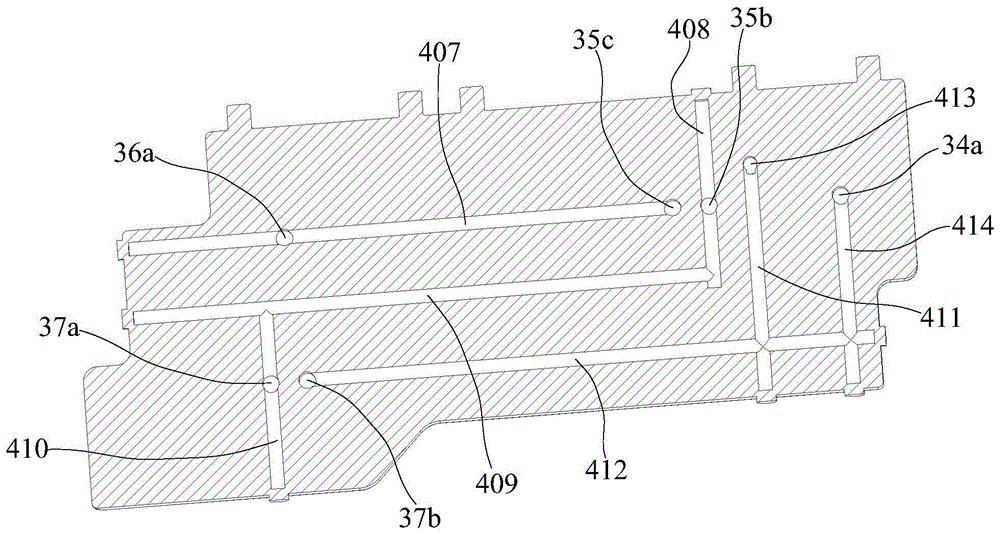
Figure 201711169164

The invention discloses an integrated waterway board and a water purifier, wherein the integrated waterway board includes a waterway board body, one of the board surfaces of the waterway board body is a mounting surface, and the sides of the waterway board body include installation sides, and The first side adjacent to the installation side; the water channel plate body is formed with a waste water straight-through channel penetrating to the installation side, a membrane filter concentrated water straight-through channel penetrating to the installation surface, and penetrating to the The enrichment valve inlet direct channel and the enrichment valve outlet direct channel on the installation surface, and the enrichment valve transfer direct channel leading to the first side, the enrichment valve transfer direct channel is located on the first side There is a plug in the flow channel opening of the membrane filter element; the inner end of the concentrated water straight channel of the membrane filter element and the inner end of the concentrated water inlet direct channel are connected with the concentrated valve transfer direct channel; the inner end of the waste water direct channel The end communicates with the inner end of the water outlet flow path of the enrichment valve. The technical scheme of the invention can improve the assembly efficiency of the water purifier.

Figure 201711169164

Description

集成水路板和净水机Integrated water board and water purifier

技术领域technical field

本发明涉及净水设备领域,特别涉及一种集成水路板和净水机。The invention relates to the field of water purification equipment, in particular to an integrated waterway board and a water purifier.

背景技术Background technique

目前,净水机已成为生活中必不可少的家用电器之一。但是由于现有的净水机,其通常通过塑胶水管将各水路部件进行连接,具有接头多、管路多、滤芯等水路部件凌乱等缺点,导致净水机的装配效率较低。At present, water purifiers have become one of the indispensable household appliances in life. However, due to the existing water purifiers, which usually connect the waterway components through plastic water pipes, there are many shortcomings such as many joints, many pipelines, and messy waterway components such as filter elements, resulting in low assembly efficiency of the water purifier.

发明内容Contents of the invention

本发明的主要目的是提出一种集成水路板,旨在提高净水机的装配效率。The main purpose of the present invention is to propose an integrated water circuit board, aiming at improving the assembly efficiency of the water purifier.

为实现上述目的,本发明提出的集成水路板用于净水机,所述集成水路板包括水路板本体,所述水路板本体的其中一板面为安装面,且所述水路板本体的侧边包括安装侧边、及与所述安装侧边相邻接的第一侧边;In order to achieve the above purpose, the integrated waterway plate proposed by the present invention is used in a water purifier, the integrated waterway plate includes a waterway plate body, one of the board surfaces of the waterway plate body is the installation surface, and the side of the waterway plate body The side includes a mounting side, and a first side adjacent to the mounting side;

所述水路板本体内形成有贯通至所述安装侧边的废水直流道、贯通至所述安装面的膜滤芯浓水直流道、贯通至所述安装面的浓缩阀入水直流道和浓缩阀出水直流道、及贯通至所述第一侧边的浓阀转接直流道,所述浓阀转接直流道的位于所述第一侧边上的流道口内设有堵头;The body of the waterway plate is formed with a waste water straight channel penetrating to the side of the installation, a membrane filter element concentrated water direct channel penetrating to the installation surface, a concentration valve inlet water passage and a concentration valve outlet water passage penetrating to the installation surface. A straight passage, and a straight passage connected to the rich valve connected to the first side, and a plug is provided in the flow opening of the straight passage located on the first side;

所述膜滤芯浓水直流道的内端和所述浓缩阀入水直流道的内端均与所述浓阀转接直流道连通;所述废水直流道的内端与所述浓缩阀出水直流道的内端连通。The inner end of the concentrated water straight channel of the membrane filter element and the inner end of the concentrated water inlet direct channel are connected with the concentrated valve transfer direct channel; the inner end of the waste water direct channel is connected with the concentrated valve outlet water direct channel. connected at the inner end.

优选地,所述浓缩阀出水直流道位于所述浓缩阀入水直流道的背离所述膜滤芯浓水直流道的一侧,且所述浓缩阀入水直流道的深度大于所述浓缩阀出水直流道的深度。Preferably, the water outlet channel of the concentration valve is located on the side of the concentration valve inlet channel away from the concentrated water channel of the membrane filter element, and the depth of the concentration valve inlet channel is greater than that of the concentration valve outlet channel. depth.

优选地,所述水路板本体内还形成有靠近所述膜滤芯浓水直流道且贯通至所述安装面的膜滤芯出水直流道、及贯通至所述安装侧边的储水直流道;Preferably, the water channel plate body is also formed with a membrane filter element outlet water flow path that is close to the membrane filter element concentrated water flow path and penetrates to the installation surface, and a water storage flow path that penetrates to the installation side;

所述膜滤芯出水直流道的内端与所述储水直流道的内端相连通。The inner end of the membrane filter core's outlet water flow path is connected with the inner end of the water storage flow flow path.

优选地,所述水路板本体内还形成有贯通至所述安装面的单向阀入水直流道和单向阀出水直流道、及贯通至所述水路板本体的侧边的膜滤出转接直流道,所述膜滤出转接直流道的位于所述水路板本体侧边上的流道口内设有堵头;Preferably, the water channel board body is also formed with a one-way valve water inlet straight channel and a one-way valve water outlet straight channel penetrating to the installation surface, and a membrane filtration adapter penetrating to the side of the water channel board body Straight-through channel, the membrane filtration transfer direct-flow channel is provided with a plug in the flow channel opening on the side of the water channel plate body;

所述膜滤芯出水直流道的内端和所述单向阀入水直流道的内端均与所述膜滤出转接直流道连通;所述单向阀出水直流道的内端与所述储水直流道的内端连通。The inner end of the water outlet straight channel of the membrane filter element and the inner end of the water inlet straight channel of the one-way valve are both connected with the membrane filtration transfer direct channel; The inner end of the water flow channel is connected.

优选地,所述水路板本体的侧边还包括与所述安装侧边相对的第二侧边;所述膜滤出转接直流道贯通至所述安装侧边;所述水路板本体内还形成有贯通至所述第一侧边的膜单间接转接直流道、及贯通至所述第二侧边的单阀入转接直流道,所述膜单间接转接直流道和所述单阀入转接直流道的位于对应侧边上的流道口内均设有堵头;Preferably, the side of the water circuit board body further includes a second side opposite to the installation side; the membrane filtration transfer straight channel penetrates to the installation side; Formed with a membrane unit indirect transfer flow channel penetrating to the first side, and a single valve inlet transfer flow channel penetrating to the second side, the membrane unit indirect transfer flow channel and the single valve input flow channel are formed. Plugs are provided in the flow channel openings located on the corresponding side of the valve into the direct flow channel;

所述膜滤出转接直流道的内端和所述单阀入转接直流道的内端均与所述膜单间接转接直流道连通;所述膜滤芯出水直流道的内端连通于所述膜滤出转接直流道,所述单向阀入水直流道的内端连通于所述单阀入转接直流道。Both the inner end of the membrane filtration direct transfer channel and the inner end of the single valve inlet transfer direct channel are connected to the membrane single indirect transfer direct channel; the inner end of the membrane filter element outlet direct channel is connected to the The membrane filters out the transfer channel, and the inner end of the one-way valve water inlet channel communicates with the single valve inlet transfer channel.

优选地,所述水路板本体的侧边还包括与所述第一侧边相对的第三侧边;所述水路板本体内还形成有贯通至所述水路板本体的另一板面的储水转接直流道、及贯通至所述第三侧边的单阀出转接直流道,所述储水转接直流道和所述单阀出转接直流道的位于所述水路板本体上的流道口内均设有堵头;Preferably, the side of the water circuit board body further includes a third side opposite to the first side; the water circuit board body is also formed with a reservoir penetrating to the other surface of the water circuit board body The water transfer straight channel and the single-valve outlet transfer channel that penetrates to the third side, the water storage transfer channel and the single-valve outlet transfer channel are located on the water circuit board body There are plugs in the flow channel openings;

所述储水转接直流道与所述单阀出转接直流道连通;所述单向阀出水直流道的内端连通于所述单阀出转接直流道的内端,所述储水直流道的内端连通于所述储水转接直流道的内端。The water storage transfer straight channel is connected with the single valve outlet transfer direct channel; the inner end of the one-way valve water outlet direct channel is connected with the inner end of the single valve outlet transfer direct channel, and the water storage The inner end of the straight channel communicates with the inner end of the water storage transfer direct channel.

优选地,所述水路板本体的侧边还包括与所述安装侧边相对的第二侧边;所述水路板本体内还形成有贯通至所述第二侧边的单储间接转接直流道,所述单储间接转接直流道的位于所述第二侧边上的流道口内设有堵头;Preferably, the side of the water circuit board body further includes a second side opposite to the installation side; the water circuit board body is also formed with a single storage indirect transfer DC channel, a plug is provided in the channel opening on the second side of the single storage indirect direct transfer channel;

所述单阀出转接直流道与所述单储间接转接直流道连通,且所述单储间接转接直流道的内端连通于所述储水转接直流道。The single-valve outlet direct transfer channel communicates with the single-storage indirect transfer direct-channel, and the inner end of the single-storage indirect transfer direct-channel communicates with the water storage direct transfer channel.

优选地,所述水路板本体的侧边还包括与所述安装侧边相对的第二侧边;所述水路板本体内还形成有贯通至所述安装面的后置滤芯入水直流道和后置滤芯出水直流道、贯通至所述安装侧边的纯净水直流道、及贯通至所述第二侧边的后滤转接直流道,所述后滤转接直流道的位于所述第二侧边上的流道口内设有堵头;Preferably, the side of the water board body further includes a second side opposite to the installation side; the water board body is also formed with a rear filter element water inlet channel and a rear filter element penetrating through the installation surface. Set the water outlet straight channel of the filter element, the pure water straight channel passing through the installation side, and the rear filter transfer direct channel passing through the second side, and the rear filter transfer direct channel is located in the second There is a plug in the flow channel opening on the side;

所述后滤转接直流道与所述单阀出转接直流道连通;所述后置滤芯入水直流道的内端连通于所述后滤转接直流道的内端,所述后置滤芯出水直流道的内端连通于所述纯净水直流道的内端。The post-filter transfer channel is connected to the single-valve output transfer channel; the inner end of the post-filter element water inlet channel is connected to the inner end of the post-filter transfer channel, and the post-filter element The inner end of the water outlet straight channel communicates with the inner end of the pure water straight channel.

优选地,所述水路板本体为一体注塑成型的注塑件,且所述水路板本体内的所有直流道均为抽芯成型的直流道。Preferably, the body of the water channel plate is an integral injection molded part, and all straight channels in the body of the water channel plate are straight channels formed by core pulling.

本发明还提出一种净水机,包括前述的集成水路板。The present invention also proposes a water purifier comprising the aforementioned integrated water circuit board.

本发明的技术方案中,由于该集成水路构件集成了膜滤芯浓水直流道、浓缩阀入水直流道、浓缩阀出水直流道及废水直流道,相较于采用独立管路和管路接头来实现净水机上膜滤芯、浓缩水控制阀及废水接头的连接的现有技术,本技术方案节省管路与管路之间连接的装配步骤,从而提高净水机的装配效率。In the technical solution of the present invention, since the integrated waterway component integrates the concentrated water straight-through channel of the membrane filter element, the straight-through water inlet channel of the concentration valve, the straight-through water outlet channel of the concentration valve and the straight-through waste water channel, compared with the use of independent pipelines and pipeline joints to achieve According to the prior art for the connection of the membrane filter element on the water purifier, the concentrated water control valve and the waste water joint, this technical solution saves the assembly steps of the connection between the pipelines, thereby improving the assembly efficiency of the water purifier.

附图说明Description of drawings

为了更清楚地说明本发明实施例或现有技术中的技术方案,下面将对实施例或现有技术描述中所需要使用的附图作简单地介绍,显而易见地,下面描述中的附图仅仅是本发明的一些实施例,对于本领域普通技术人员来讲,在不付出创造性劳动的前提下,还可以根据这些附图示出的结构获得其他的附图。In order to more clearly illustrate the technical solutions in the embodiments of the present invention or the prior art, the following will briefly introduce the drawings that need to be used in the description of the embodiments or the prior art. Obviously, the accompanying drawings in the following description are only These are some embodiments of the present invention. For those skilled in the art, other drawings can also be obtained according to the structures shown in these drawings without creative effort.

图1为本发明集成水路板一实施例的结构示意图;Fig. 1 is a schematic structural view of an embodiment of the integrated waterway board of the present invention;

图2为图1中沿A-A方向的截面示意图;Fig. 2 is a schematic cross-sectional view along the A-A direction in Fig. 1;

图3为图1中沿B-B方向的截面示意图;Fig. 3 is a schematic cross-sectional view along the B-B direction in Fig. 1;

图4为图1中平行于集成水路板的安装面且过原水直流道的截面示意图;Fig. 4 is a schematic cross-sectional view parallel to the installation surface of the integrated water circuit board in Fig. 1 and passing through the raw water flow channel;

图5为图1中沿C-C方向的截面示意图;Fig. 5 is a schematic cross-sectional view along the C-C direction in Fig. 1;

图6为图1中沿D-D方向的截面示意图;Fig. 6 is a schematic cross-sectional view along the D-D direction in Fig. 1;

图7为图1中沿E-E方向的截面示意图;Fig. 7 is a schematic cross-sectional view along the E-E direction in Fig. 1;

图8为图1中平行于集成水路板的安装面且过浓阀转接直流道的截面示意图;Fig. 8 is a cross-sectional schematic view parallel to the installation surface of the integrated water circuit board in Fig. 1 and the over-concentration valve is transferred to the direct flow channel;

图9为图1中沿F-F方向的截面示意图;Fig. 9 is a schematic cross-sectional view along the F-F direction in Fig. 1;

图10为图1中沿G-G方向的截面示意图;Fig. 10 is a schematic cross-sectional view along the G-G direction in Fig. 1;

图11为本发明净水机一实施例的水路结构示意图。Fig. 11 is a schematic diagram of the waterway structure of an embodiment of the water purifier of the present invention.

附图标号说明:Explanation of reference numbers:
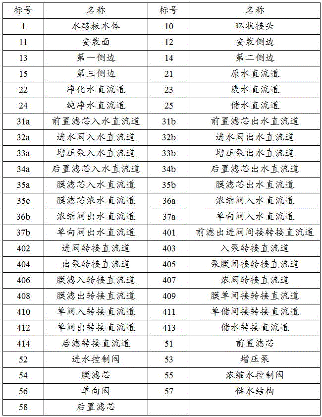
Figure SMS_1
Figure SMS_1

本发明目的的实现、功能特点及优点将结合实施例,参照附图做进一步说明。The realization of the purpose of the present invention, functional characteristics and advantages will be further described in conjunction with the embodiments and with reference to the accompanying drawings.

具体实施方式Detailed ways

下面将结合本发明实施例中的附图,对本发明实施例中的技术方案进行清楚、完整地描述,显然,所描述的实施例仅仅是本发明的一部分实施例,而不是全部的实施例。基于本发明中的实施例,本领域普通技术人员在没有作出创造性劳动前提下所获得的所有其他实施例,都属于本发明保护的范围。The following will clearly and completely describe the technical solutions in the embodiments of the present invention with reference to the accompanying drawings in the embodiments of the present invention. Obviously, the described embodiments are only part of the embodiments of the present invention, not all of them. Based on the embodiments of the present invention, all other embodiments obtained by persons of ordinary skill in the art without creative efforts fall within the protection scope of the present invention.

需要说明,若本发明实施例中有涉及方向性指示(诸如上、下、左、右、前、后……),则该方向性指示仅用于解释在某一特定姿态(如附图所示)下各部件之间的相对位置关系、运动情况等,如果该特定姿态发生改变时,则该方向性指示也相应地随之改变。It should be noted that if there are directional indications (such as up, down, left, right, front, back...) in the embodiment of the present invention, the directional indications are only used to explain how to move in a certain posture (as shown in the accompanying drawings). If the specific posture changes, the directional indication will also change accordingly.

另外,若本发明实施例中有涉及“第一”、“第二”等的描述,则该“第一”、“第二”等的描述仅用于描述目的,而不能理解为指示或暗示其相对重要性或者隐含指明所指示的技术特征的数量。由此,限定有“第一”、“第二”的特征可以明示或者隐含地包括至少一个该特征。另外,各个实施例之间的技术方案可以相互结合,但是必须是以本领域普通技术人员能够实现为基础,当技术方案的结合出现相互矛盾或无法实现时应当认为这种技术方案的结合不存在,也不在本发明要求的保护范围之内。In addition, if there are descriptions involving "first", "second" and so on in the embodiments of the present invention, the descriptions of "first", "second" and so on are only for descriptive purposes, and should not be interpreted as indicating or implying Its relative importance or implicitly indicates the number of technical features indicated. Thus, the features defined as "first" and "second" may explicitly or implicitly include at least one of these features. In addition, the technical solutions of the various embodiments can be combined with each other, but it must be based on the realization of those skilled in the art. When the combination of technical solutions is contradictory or cannot be realized, it should be considered that the combination of technical solutions does not exist , nor within the scope of protection required by the present invention.

本发明提出一种集成水路板、以及一种具有该集成水路板的净水机。The invention provides an integrated water circuit board and a water purifier with the integrated water circuit board.

参照图1至图3,在本发明一实施例中,该集成水路板包括水路板本体1,水路板本体1的其中一板面为安装面11,且其邻接于安装面11的一侧边为安装侧边12;1 to 3, in an embodiment of the present invention, the integrated water circuit board includes a water circuit board body 1, one of the board surfaces of the water circuit board body 1 is the installation surface 11, and it is adjacent to one side of the installation surface 11 For mounting side 12;

水路板本体1内形成有贯通至安装侧边12的原水直流道21和净化水直流道22、及贯通至安装面11的前置滤芯入水直流道31a和前置滤芯出水直流道31b,原水直流道21的内端与前置滤芯入水直流道31a的内端连通,前置滤芯出水直流道31b的内端与净化水直流道22的内端连通。可以理解,本实施例中,水路板本体1内所形成的所有直流道均延伸至水路板本体1的外表面,而具有显露在水路板本体1外表面的流道口,以使每一直流道均能通过其流道口与对应的其他水路部件实现连接。本实施例中,原水直流道21和净化水直流道22分别用以供净水机的原水接头和净化水接头连接;前置滤芯入水直流道31a和前置滤芯出水直流道31b则用以供净水机的前置滤芯(可以当不限于为PAC前置滤芯)连接。另外,本实施例中,前置滤芯入水直流道31a和前置滤芯出水直流道31b是相靠近设置的,可便于实现与前置滤芯上通常相靠近设置的两个水接头相对位连接。The water channel plate body 1 is formed with a raw water direct channel 21 and a purified water direct channel 22 penetrating to the installation side 12, and a pre-filter element water inlet direct channel 31a and a pre-filter element outlet water direct channel 31b penetrating to the installation surface 11, so that the raw water flows through The inner end of the channel 21 is communicated with the inner end of the pre-filter element water inlet direct passage 31a, and the inner end of the pre-filter element outlet water direct passage 31b is communicated with the inner end of the purified water direct flow passage 22. It can be understood that in this embodiment, all the straight channels formed in the water circuit board body 1 extend to the outer surface of the water circuit board body 1, and have flow channel openings exposed on the outer surface of the water circuit board body 1, so that each straight channel All of them can be connected with other corresponding waterway components through their flow channel openings. In this embodiment, the raw water direct channel 21 and the purified water direct channel 22 are used to connect the raw water joint and the purified water joint of the water purifier respectively; The pre-filter of the water purifier (can be used as but not limited to the PAC pre-filter) is connected. In addition, in this embodiment, the pre-filter element water inlet channel 31a and the pre-filter element outlet water channel 31b are arranged close to each other, which can facilitate the relative connection with the two water joints usually arranged close to each other on the pre-filter element.

本发明的技术方案中,由于该集成水路板集成了原水直流道21、净化水直流道22、前置滤芯入水直流道31a和前置滤芯出水直流道31b,相较于采用独立管路和管路接头来实现净水机上原水接头、净化水接头与前置滤芯的连接的现有技术,本技术方案节省管路与管路之间连接的装配步骤,从而提高净水机的装配效率。In the technical solution of the present invention, since the integrated water circuit board integrates the raw water direct channel 21, the purified water direct channel 22, the pre-filter element water inlet direct channel 31a and the pre-filter element water outlet direct channel 31b, compared with the independent pipeline and pipe In the prior art, the connection between the raw water joint, the purified water joint and the pre-filter element on the water purifier is achieved through the road joint. This technical solution saves the assembly steps of the connection between the pipelines, thereby improving the assembly efficiency of the water purifier.

另外,本实施例中,水路板本体1优选为一体注塑成型的注塑件,且水路板本体1内的所有流道均为抽芯成型的直流道,如此,相较于现有技术中普遍采用两块基板焊接成集成水路板的方式,能有效避免产品焊接不良、甚至焊接报废的情况,从而提高基层水路构件的产品良率,降低集成水路板的量产成本。然本设计不限于此,于其他实施例中,水路板本体1内的流道也可但不限于通过钻孔成型等方式实现。In addition, in this embodiment, the water channel plate body 1 is preferably an integral injection molded part, and all the flow channels in the water channel plate body 1 are straight channels formed by core pulling. The method of welding two substrates into an integrated water circuit board can effectively avoid poor welding of products or even scrapped welding, thereby improving the product yield of basic water circuit components and reducing the mass production cost of integrated water circuit boards. However, the present design is not limited thereto. In other embodiments, the flow channels in the water channel plate body 1 can also be realized by drilling and forming, but not limited to.

本实施例中,水路板本体1所采用的注塑材料优选为POM塑料或PP塑料与玻璃纤维的混合材料,这些注塑材料强度较高,有利于降低直流道在抽芯成型过程中出现塌陷形变的概率。进一步地,本实施例中,水路板本体1上的每一直流道设置为圆形流道;可以理解,圆形具有较好的张力而具有较好的形状稳定性,因此,将水路板本体1上所成形的直流道设置为圆形流道,有利于避免抽芯成型过程中出现塌陷形变。另外,本实施例中,优选地,所有直流道均垂直于对应的板面或侧边;可以理解,若直流道倾斜于所在板面或侧边,则必然会导致直流道与所在板面或侧边之间形成位于其倾斜方向一侧的锐角,显然,锐角较尖的特性,会使其容易在抽芯成型的过程中发生形变、以及容易碰损。In this embodiment, the injection molding material used for the waterway board body 1 is preferably a mixture of POM plastic or PP plastic and glass fiber. These injection molding materials have high strength and are beneficial to reduce the risk of collapse and deformation of the straight channel during the core-pulling molding process. probability. Further, in this embodiment, each straight channel on the water channel plate body 1 is set as a circular channel; it can be understood that the circular shape has better tension and better shape stability, therefore, the water channel plate body The straight channel formed on 1 is set as a circular channel, which is beneficial to avoid collapse and deformation during the core-pulling forming process. In addition, in this embodiment, preferably, all straight channels are perpendicular to the corresponding board or side; it can be understood that if the straight channel is inclined to the board or side, it will inevitably cause the straight channel to be perpendicular to the board or side. An acute angle is formed between the sides on one side of the inclined direction. Obviously, the sharper nature of the acute angle makes it easy to deform and be easily damaged during the core-pulling molding process.

一并参照图4,在本实施例中,进一步地,原水直流道21连通于前置滤芯入水直流道31a的背向前置滤芯出水直流道31b的一侧,并且,净化水直流道22连通于前置滤芯出水直流道31b的背向前置滤芯入水直流道31a的一侧,如此,可使得原水直流道21上的原水进口与净化水直流道22上的净化水出口之间有更宽的间隔,以便于原水接头、净化水接头与原水流道、净化水流道之间的一一对应装拆,从而便于原水接头和净化水接头的更换。Referring to Fig. 4 together, in this embodiment, further, the raw water straight-through channel 21 communicates with the side of the pre-filter element water-flow straight-through channel 31a facing away from the pre-filter element outlet water straight-through channel 31b, and the purified water straight-through channel 22 communicates with On the side of the pre-filter element water outlet flow path 31b facing away from the front filter element water flow path 31a, so that there is a wider gap between the raw water inlet on the raw water flow path 21 and the purified water outlet on the purified water flow path 22. The distance between the raw water connector and the purified water connector is convenient for the one-to-one corresponding assembly and disassembly of the raw water flow channel and the purified water flow channel, thereby facilitating the replacement of the raw water connector and the purified water connector.

在本实施例中,进一步地,水路板本体1内还形成有贯通至安装面11的进水阀入水直流道32a和进水阀出水直流道32b,进水阀入水直流道32a的内端与净化水直流道22的内端连通。本实施例中,进水阀入水直流道32a和进水阀出水直流道32b用以供净水机的进水控制阀52连接。可以理解,集成水路板上进水阀入水直流道32a和进水阀出水直流道32b的额外集成,可进一步节省前置滤芯与进水控制阀52之间的管路装配步骤,从而进一步提高净水机的装配效率。In this embodiment, further, the water channel plate body 1 is also formed with a water inlet valve direct passage 32a and a water inlet valve outlet passage 32b that penetrate to the installation surface 11, and the inner end of the water inlet valve direct passage 32a is connected to the The inner end of the purified water straight channel 22 is connected. In this embodiment, the water inlet valve direct passage 32a and the water inlet valve outlet direct passage 32b are used for connecting the water inlet control valve 52 of the water purifier. It can be understood that the additional integration of the water inlet valve inlet straight channel 32a and the water inlet valve outlet water straight channel 32b on the integrated water circuit board can further save the pipeline assembly steps between the pre-filter element and the water inlet control valve 52, thereby further improving the cleanliness. The assembly efficiency of the water machine.

参照图4,本实施例中,水路板本体1还具有邻接于安装侧边12的第一侧边13,原水直流道21相较净化水直流道22更靠近第一侧边13设置。进一步地,水路板本体1内还形成有贯通至第一侧边13的前滤出进阀间接转接直流道401,且前滤出进阀间接转接直流道401的位于第一侧边13上的流道口内设有堵头;该前滤出进阀间接转接直流道401的内端与净化水直流道22的内端连通,进水阀入水直流道32a的内端与前滤出进阀间接转接直流道401连通。即是说,本实施例中,净化水直流道22与进水阀入水直流道32a是通过前滤出进阀间接转接直流道401进行转接的;然本设计不限于此,于其他实施例中,净化水直流道22与进水阀入水直流道32a也可直接连通。可以理解,由于前置滤芯出水直流道31b的内端与净化水直流道22的内端是连通的,故而进水阀入水直流道32a与前置滤芯出水直流道31b也是连通的。Referring to FIG. 4 , in this embodiment, the waterway plate body 1 also has a first side 13 adjacent to the installation side 12 , and the raw water flow channel 21 is arranged closer to the first side 13 than the purified water flow channel 22 . Further, the water channel plate body 1 is also formed with a front filter inlet and outlet valve indirect transfer channel 401 that penetrates to the first side 13, and the front filter outlet and inlet valve indirect transfer channel 401 is located on the first side 13 There is a plug in the flow channel opening on the top; the inner end of the direct transfer channel 401 of the front filter inlet valve is connected with the inner end of the purified water direct channel 22, and the inner end of the water inlet valve inlet direct channel 32a is connected with the front filter outlet The inlet valve is directly connected to the direct-flow passage 401. That is to say, in the present embodiment, the purified water direct passage 22 and the water inlet valve direct passage 32a are connected through the direct connection direct passage 401 through the front filtering inlet valve; In an example, the purified water flow channel 22 may also be directly communicated with the water inlet valve flow flow channel 32a. It can be understood that since the inner end of the pre-filter element outlet straight passage 31b is connected to the inner end of the purified water straight passage 22, the water inlet valve inlet straight passage 32a is also connected with the pre-filter element outlet straight passage 31b.

在本实施例中,水路板本体1还具有与安装侧边12相对的第二侧边14。进一步地,水路板本体1内还形成有贯通至第二侧边14的进阀转接直流道402,且进阀转接直流道402的位于第二侧边14上的流道口内设有堵头;该进阀转接直流道402的内端与前滤出进阀间接转接直流道401连通,进水阀入水直流道32a的内端与进阀转接直流道402连通。即是说,本实施例中,进水阀入水直流道32a是依次经进阀转接直流道402和前滤出进阀间接转接直流道401再与净化水直流道22连通的。可以理解,进阀转接直流道402的增设,可使得进水阀入水直流道32a的位置设置到水路板本体1上更为合适的位置,以便于进水阀的安装。另外,本实施例中,进阀转接直流道402优选是与净化水直流道22相并行延伸的,而前滤出进阀间接转接直流道401与进阀转接直流道402、净化水直流道22均垂直设置,如此,前滤出进阀间接转接直流道401的设置所实现的是进水阀入水直流道32a相对前置滤芯出水直流道31b的横向平移,而进阀转接直流道402的设置所实现的是进水阀入水直流道32a相对前置滤芯出水直流道31b的纵向平移(以净化水直流道22的延伸方向为纵向)。In this embodiment, the waterway board body 1 also has a second side 14 opposite to the installation side 12 . Further, there is also formed in the main body 1 of the water channel board 1 an inlet valve transfer direct passage 402 that penetrates to the second side 14, and the flow passage opening of the inlet valve transfer direct passage 402 located on the second side 14 is provided with a plug. head; the inner end of the inlet valve transfer channel 402 is communicated with the front filtering inlet valve indirect transfer channel 401, and the inner end of the water inlet valve direct channel 32a is communicated with the inlet valve transfer channel 402. That is to say, in the present embodiment, the water inlet valve direct passage 32a is connected with the purified water direct passage 22 through the inlet valve transfer direct passage 402 and the pre-filtered inlet valve indirect transfer direct passage 401 in sequence. It can be understood that the addition of the inlet valve transfer channel 402 can make the position of the water inlet valve inlet direct channel 32a be set to a more suitable position on the water circuit board body 1, so as to facilitate the installation of the water inlet valve. In addition, in this embodiment, the inlet valve transfer channel 402 is preferably extended in parallel with the purified water channel 22, while the pre-filter inlet valve indirect transfer channel 401 and the inlet valve transfer channel 402, purified water The direct passages 22 are all vertically arranged. In this way, the setting of the indirect transfer direct passage 401 of the front filter outlet and inlet valve realizes the lateral translation of the water inlet direct passage 32a relative to the pre-filter element outlet direct passage 31b, and the transfer of the inlet valve What the setting of the straight channel 402 achieves is the longitudinal translation of the water inlet valve inlet straight channel 32a relative to the pre-filter element outlet water straight channel 31b (taking the extension direction of the purified water straight channel 22 as the longitudinal direction).

参照图4和图5,在本实施例中,进一步地,水路板本体1内还形成有贯通至安装面11的增压泵入水直流道33a、增压泵出水直流道33b、及贯通至水路板本体1一侧边的入泵转接直流道403,该入泵转接直流道403的位于水路板本体1对应侧边上的流道口内设有堵头。本实施例中,增压泵入水直流道33a和增压泵出水直流道33b用以供净水机的增压泵连接。增压泵入水直流道33a的内端和进水阀出水直流道32b的内端均与入泵转接直流道403连通。即是说,本实施例中,增压泵入水直流道33a与进水阀出水直流道32b是通过前滤出进阀间接转接直流道401进行转接的;然本设计不限于此,于其他实施例中,也可将增压泵入水直流道33a设置为贯通至水路板本体1侧边的直流道,如此,增压泵入水直流道33a也可与进水阀出水直流道32b直接连通。本实施例中,入泵转接直流道403的增设,可使得增压泵入水直流道33a与进水阀出水直流道32b均设置在安装面11上,以便于进水阀和增压泵均可在安装面11上得到与集成水路板的连接。另外,类似地,本实施例中,集成水路板上增压泵入水直流道33a的额外集成,可进一步节省进水控制阀52与增压泵之间的管路装配步骤,从而进一步提高净水机的装配效率。Referring to Fig. 4 and Fig. 5, in this embodiment, further, in the water channel plate body 1, there are also formed a booster pump inflow channel 33a, a booster pump outflow channel 33b, and a channel leading to the waterway through the installation surface 11. The inlet pump on one side of the board body 1 is connected to the direct flow channel 403 , and the flow channel opening of the inlet pump transfer channel 403 on the corresponding side of the water circuit board body 1 is provided with a plug. In this embodiment, the booster pump water inflow channel 33a and the booster pump outlet water channel 33b are used to connect the booster pump of the water purifier. Both the inner end of the booster pump inlet straight passage 33 a and the inner end of the water inlet valve outlet straight passage 32 b communicate with the pump inlet direct passage 403 . That is to say, in this embodiment, the booster pump inlet water straight passage 33a and the water inlet valve outlet water straight passage 32b are connected through the direct connection direct passage 401 through the front filtering inlet valve; however, the design is not limited thereto, and In other embodiments, the booster pump inlet water channel 33a can also be set as a channel through the side of the water board body 1, so that the booster pump inlet water channel 33a can also be directly connected with the water inlet valve outlet channel 32b . In this embodiment, the addition of the direct-flow channel 403 for the pump inlet can make the direct-flow channel 33a of the booster pump and the direct-flow channel 32b of the water inlet valve be arranged on the installation surface 11, so that the water inlet valve and the booster pump can be connected to each other. The connection to the integrated water circuit board can be obtained on the mounting surface 11 . In addition, similarly, in this embodiment, the additional integration of the booster pump inlet water flow channel 33a on the integrated water circuit board can further save the pipeline assembly steps between the water inlet control valve 52 and the booster pump, thereby further improving the quality of water purification. Machine assembly efficiency.

本实施例中,进一步地,入泵转接直流道403所贯通至的水路板本体1的侧边为第二侧边14;然本设计不限于此,于其他实施例中,入泵转接直流道403也可贯通至水路板本体1的第一侧边13,然而,相较于贯通至第一侧边13,入泵转接直流道403贯通至第二侧边14(其中,安装侧边12为水路板本体1的长边,第一侧边13为水路板本体1的宽边),只需要进一步增加水路板本体1的宽度即可,而无需将水路板本体1做得过长。In this embodiment, further, the side of the waterway plate body 1 through which the direct-flow channel 403 is connected to the pump is the second side 14; however, the design is not limited to this, and in other embodiments, the The straight channel 403 can also penetrate to the first side 13 of the water circuit board body 1, however, compared to the first side 13, the pump-in transfer direct channel 403 penetrates to the second side 14 (wherein, the installation side side 12 is the long side of the water board body 1, and the first side 13 is the wide side of the water board body 1), it is only necessary to further increase the width of the water board body 1 without making the water board body 1 too long .

参照图4、图6和图8,在本实施例中,进一步地,水路板本体1内还形成有贯通至安装面11的后置滤芯入水直流道34a、后置滤芯出水直流道34b、及膜滤芯入水直流道35a、膜滤芯浓水直流道35c和膜滤芯出水直流道35b,以及形成有贯通至水路板本体1的侧边的出泵转接直流道404和膜滤出转接直流道408,该出泵转接直流道404和膜滤出转接直流道408的位于水路板本体1侧边上的流道口内均设有堵头;其中,增压泵出水直流道33b的内端和膜滤芯入水直流道35a的内端均与出泵转接直流道404连通;膜滤芯出水直流道35b的内端和后置滤芯入水直流道34a的内端均与膜滤出转接直流道408连通。类似地,出泵转接直流道404的设置,可使得增压泵出水直流道33b和膜滤芯入水直流道35a均设置在安装面11上;膜滤出转接直流道408的设置,则可使得膜滤芯出水直流道35b和后置滤芯入水直流道34a均设置在安装面11上。Referring to Fig. 4, Fig. 6 and Fig. 8, in this embodiment, further, the water channel plate body 1 is also formed with a rear filter element water flow channel 34a penetrating to the installation surface 11, a rear filter element water flow channel 34b, and Membrane filter element water inlet direct channel 35a, membrane filter element concentrated water direct channel 35c and membrane filter element outlet water direct channel 35b, as well as a pump outlet transfer direct channel 404 and a membrane filter outlet transfer direct channel formed through the side of the water circuit board body 1 408, plugs are provided in the flow channel openings on the side of the water board body 1 of the outlet pump transfer channel 404 and the membrane filtration transfer channel 408; wherein, the inner end of the booster pump outlet channel 33b and the inner end of the membrane filter element water inlet direct passage 35a are all connected with the outlet pump transfer direct passage 404; 408 connected. Similarly, the setting of the direct-flow passage 404 for the pump outlet can make the booster pump outlet direct-flow passage 33b and the water-inflow direct passage 35a of the membrane filter element all be arranged on the installation surface 11; the setting of the membrane filtration direct-flow passage 408 can then So that the membrane filter element outlet flow channel 35b and the rear filter element water inlet flow channel 34a are both arranged on the installation surface 11 .

本实施例中,膜滤芯入水直流道35a、膜滤芯浓水直流道35c和膜滤芯出水直流道35b用以供净水机的膜滤芯(可以但不限于是RO膜滤芯)连接;后置滤芯入水直流道34a和后置滤芯出水直流道34b则用以供净水机的后置滤芯(可以但不限于为用以改善口感的活性炭后置滤芯)连接。类似地,本实施例中,集成水路板上膜滤芯入水直流道35a、膜滤芯出水直流道35b、后置滤芯入水直流道34a和后置滤芯出水直流道34b的额外集成,可进一步节省增压泵、膜滤芯及后置滤芯之间的管路装配步骤,从而进一步提高净水机的装配效率。另外,本实施例中,后置滤芯入水直流道34a和后置滤芯出水直流道34b是相靠近设置的,可便于实现与后置滤芯上通常相靠近设置的两个水接头相对位连接;膜滤芯入水直流道35a、膜滤芯浓水直流道35c和膜滤芯出水直流道35b是相靠近设置的,则可便于实现与膜滤芯上通常相靠近设置的三个水接头相对位连接。In this embodiment, the membrane filter element water inlet channel 35a, the membrane filter element concentrated water channel 35c and the membrane filter element outlet water channel 35b are used to connect the membrane filter element (which can be but not limited to RO membrane filter element) of the water purifier; the rear filter element The straight water inlet channel 34a and the post filter element outlet straight channel 34b are used for connecting the rear filter element of the water purifier (which may be but not limited to an activated carbon post filter element for improving taste). Similarly, in this embodiment, the additional integration of the membrane filter element water inlet channel 35a, the membrane filter element outlet water channel 35b, the rear filter element water inlet channel 34a and the rear filter element outlet water channel 34b on the integrated water circuit board can further save pressure. The pipeline assembly steps between the pump, the membrane filter element and the post-filter element further improve the assembly efficiency of the water purifier. In addition, in this embodiment, the post-filter element water inlet direct channel 34a and the post-filter element outlet water direct channel 34b are arranged close to each other, which can facilitate the relative connection with the two water joints usually arranged close to each other on the post-install filter element; The filter element water inlet straight channel 35a, the membrane filter element concentrated water straight channel 35c and the membrane filter element outlet water straight channel 35b are arranged close to each other, which can facilitate the relative connection with the three water joints usually arranged close to each other on the membrane filter element.

参照图4和图10,进一步地,水路板本体1内还形成有贯通至安装侧边12的纯净水直流道24;后置滤芯出水直流道34b的内端连通于纯净水直流道24的内端。本实施例中,纯净水直流道24用以供净水机的纯净水接头连接。可以理解,集成水路板上纯净水直流道24的额外集成,可节省独立纯净水水管的装配步骤,从而进一步提高净水机的装配效率。Referring to Fig. 4 and Fig. 10, further, a pure water flow channel 24 penetrating to the installation side 12 is also formed in the water channel plate body 1; end. In this embodiment, the pure water straight-through channel 24 is used for connecting the pure water connector of the water purifier. It can be understood that the additional integration of the pure water straight channel 24 on the integrated water circuit board can save the assembly steps of the independent pure water pipe, thereby further improving the assembly efficiency of the water purifier.

本实施例中,水路板本体1还具有与第一侧边13相对的第三侧边15。进一步地,出泵转接直流道404贯通至第二侧边14;水路板本体1内还形成有贯通至第三侧边15的泵膜间接转接直流道405,泵膜间接转接直流道405的位于第三侧边15上的流道口内设有堵头;并且,出泵转接直流道404的内端与泵膜间接转接直流道405的内端连通,增压泵出水直流道33b的内端连通于出泵转接直流道404,膜滤芯入水直流道35a的内端与泵膜间接转接直流道405连通。本实施例中,泵膜间接转接直流道405的增设,可实现增压泵出水直流道33b相对于膜滤芯入水直流道35a的横向偏移,以使得增压泵出水直流道33b可更靠近增压泵入水直流道33a设置。另外,本实施例中,进阀转接直流道402位于入泵转接直流道403与出泵转接直流道404之间;然本设计不限于此,于其他实施例中,也可将入泵转接直流道403设置在进阀转接直流道402与出泵转接直流道404之间。In this embodiment, the waterway plate body 1 also has a third side 15 opposite to the first side 13 . Further, the pump-outlet transfer direct-flow channel 404 runs through to the second side 14; the pump membrane indirect transfer direct-flow channel 405 penetrating to the third side 15 is also formed in the water channel plate body 1, and the pump membrane indirectly transfers to the direct-flow channel 405. 405 is provided with a plug in the flow channel opening on the third side 15; and, the inner end of the pump outlet transfer straight channel 404 communicates with the inner end of the pump membrane indirect transfer direct channel 405, and the booster pump outlet water direct channel The inner end of 33b is communicated with the direct transfer passage 404 of the pump outlet, and the inner end of the membrane filter element water inlet direct passage 35a is communicated with the indirect direct transfer passage 405 of the pump membrane. In this embodiment, the addition of the pump membrane indirect transfer channel 405 can realize the lateral offset of the booster pump outlet water channel 33b relative to the membrane filter element water inlet channel 35a, so that the booster pump outlet water channel 33b can be closer to The booster pump is set into the water flow channel 33a. In addition, in this embodiment, the inlet valve direct passage 402 is located between the inlet pump direct passage 403 and the outlet pump direct passage 404; The pump transfer straight channel 403 is arranged between the inlet valve transfer direct channel 402 and the pump outlet direct transfer channel 404 .

在本实施例中,进一步地,水路板本体1内还形成有与出泵转接直流道404相间隔、且贯通至第二侧边14的膜滤入转接直流道406,膜滤入转接直流道406的位于第二侧边14上的流道口内设有堵头;并且,膜滤入转接直流道406与泵膜间接转接直流道405连通;膜滤芯入水直流道35a的内端连通于膜滤入转接直流道406。本实施例中,出泵转接直流道404位于进阀转接直流道402与膜滤入转接直流道406之间。可以理解,膜滤入转接直流道406的增设,可实现泵膜间接转接直流道405相对于前滤出进阀间接转接直流道401的纵向偏移,以避免出泵转接直流道404与前滤出进阀间接转接直流道401易于出现相交的情形。In this embodiment, further, the water channel plate body 1 is further formed with a membrane filter direct-flow channel 406 that is spaced from the outlet pump transfer direct-flow channel 404 and penetrates to the second side 14. A plug is provided in the flow channel opening on the second side 14 of the direct flow channel 406; and the membrane filter enters the direct transfer channel 406 and communicates with the pump membrane indirect transfer direct channel 405; the membrane filter element enters the water flow channel 35a The end communicates with the membrane filter and enters the transfer channel 406. In this embodiment, the pump outlet direct passage 404 is located between the inlet valve direct passage 402 and the membrane filter inlet direct passage 406 . It can be understood that the addition of the direct transfer channel 406 for membrane filtration can realize the longitudinal offset of the indirect direct transfer channel 405 of the pump membrane relative to the indirect transfer direct channel 401 of the front filter inlet valve, so as to avoid the direct transfer channel of the pump outlet. 404 is likely to intersect with the indirect direct transfer channel 401 of the front filter inlet valve.

一并参照图6和图7,在本实施例中,进一步地,水路板本体1内还形成有贯通至安装侧边12的废水直流道23、贯通至安装面11的浓缩阀入水直流道36a和浓缩阀出水直流道36b、及贯通至第一侧边13的浓阀转接直流道407,该浓阀转接直流道407的位于第一侧边13上的流道口内设有堵头;其中,膜滤芯浓水直流道35c的内端和浓缩阀入水直流道36a的内端均与浓阀转接直流道407连通;废水直流道23的内端与浓缩阀出水直流道36b的内端连通。本实施例中,浓缩阀入水直流道36a和浓缩阀出水直流道36b用以供净水机的浓缩水控制阀55连接;废水直流道23则用以供净水机的废水接头连接。类似地,本实施例中,集成水路板上浓缩阀入水直流道36a、浓缩阀出水直流道36b及废水直流道23的额外集成,可进一步节省膜滤芯、浓缩水控制阀55及废水接头之间的管路装配步骤,从而进一步提高净水机的装配效率。另外,类似地,浓阀转接直流道407的设置,可使得膜滤芯浓水直流道35c和浓缩阀入水直流道36a均设置在安装面11上。Referring to FIG. 6 and FIG. 7 together, in this embodiment, further, the water channel plate body 1 is also formed with a waste water flow channel 23 penetrating to the installation side 12 and a concentration valve water inflow channel 36a penetrating to the installation surface 11. And the concentration valve outlet water flow passage 36b, and the concentration valve transfer passage 407 connected to the first side 13, the flow passage opening of the concentration valve transfer passage 407 located on the first side 13 is provided with a plug; Wherein, the inner end of the membrane filter element concentrated water direct passage 35c and the inner end of the concentration valve inlet direct passage 36a are all communicated with the concentrated valve transfer direct passage 407; the inner end of the waste water direct passage 23 is connected with the inner end of the concentration valve outlet water direct passage 36b connected. In this embodiment, the concentrated water inlet straight channel 36a and the concentrated valve outlet water straight channel 36b are used for connecting the concentrated water control valve 55 of the water purifier; the waste water straight channel 23 is used for connecting the waste water joint of the water purifier. Similarly, in this embodiment, the additional integration of the concentration valve inlet straight channel 36a, the concentration valve outlet water straight channel 36b and the waste water straight channel 23 on the integrated water circuit board can further save the space between the membrane filter element, the concentrated water control valve 55 and the waste water connector. Pipeline assembly steps, thereby further improving the assembly efficiency of the water purifier. In addition, similarly, the arrangement of the enriched valve direct passage 407 can make the concentrated water direct passage 35c of the membrane filter element and the concentrated water inlet direct passage 36a both be arranged on the installation surface 11 .

本实施例中,优选地,浓缩阀出水直流道36b位于浓缩阀入水直流道36a的背离膜滤芯浓水直流道35c的一侧,且浓缩阀入水直流道36a的深度大于浓缩阀出水直流道36b的深度,以使浓缩阀入水直流道36a的内端在深度方向上突出于浓缩阀出水直流道36b的内端,而与在浓缩阀出水直流道36b深度方向上与浓缩阀出水直流道36b间隔设置的前滤出进阀间接转接直流道401相连通。然本设计不限于此,于其他实施例中,可使浓缩阀出水直流道36b与浓缩阀入水直流道36a的连线、与浓缩阀入水直流道36a与膜滤芯浓水直流道35c的连线呈相交设置,此时,浓缩阀出水直流道36b的深度和浓缩阀入水直流道36a的深度也可一致。In this embodiment, preferably, the concentration valve outlet water passage 36b is located on the side of the concentration valve inlet water passage 36a away from the membrane filter element concentrated water passage 35c, and the concentration valve inlet water passage 36a is deeper than the concentration valve outlet water passage 36b depth, so that the inner end of the concentration valve inlet flow channel 36a protrudes from the inner end of the concentration valve outlet flow channel 36b in the depth direction, and is spaced from the concentration valve outlet flow channel 36b in the depth direction of the concentration valve outlet flow channel 36b The pre-filtered inlet and outlet valves are directly connected to the straight-through channel 401 to communicate with each other. However, the present design is not limited thereto. In other embodiments, the connection line between the concentration valve outlet water passage 36b and the concentration valve inlet water passage 36a, and the connection line between the concentration valve inlet water passage 36a and the concentrated water flow passage 35c of the membrane filter element They are intersecting. At this time, the depth of the concentration valve outlet water flow channel 36b and the depth of the concentration valve water flow flow channel 36a can also be consistent.

参照图8和图9,在本实施例中,进一步地,水路板本体1内还形成有贯通至安装侧边12的储水直流道25;膜滤芯出水直流道35b的内端与储水直流道25的内端相连通。本实施例中,储水直流道25的增设,可实现在净水机上增加用以储存经膜滤芯过滤后的纯水的储水结构57(例如但不限于储水罐、储水袋等),可以理解,储水结构57的增设,可实现未用纯水时,对纯水的储存,到用水时,在利用储水结构57中的压力将纯水经后置滤芯排出引用。Referring to Fig. 8 and Fig. 9, in this embodiment, further, a water storage straight channel 25 penetrating to the installation side 12 is also formed in the water channel plate body 1; The inner ends of the channel 25 are connected. In this embodiment, the addition of the straight water storage channel 25 can realize the addition of a water storage structure 57 (such as but not limited to a water storage tank, a water storage bag, etc.) for storing pure water filtered by a membrane filter element on the water purifier. It can be understood that the addition of the water storage structure 57 can realize the storage of pure water when the pure water is not used, and when the water is used, the pressure in the water storage structure 57 is used to discharge the pure water through the rear filter element for reference.

参照图8,在本实施例中,进一步地,水路板本体1内还形成有贯通至安装面11的单向阀入水直流道37a和单向阀出水直流道37b;单向阀入水直流道37a的内端与膜滤出转接直流道408连通。即是说,本实施例中,膜滤芯出水直流道35b经膜滤出转接直流道408与单向阀入水直流道37a连通。本实施例中,单向阀入水直流道37a和单向阀出水直流道37b用以供净水机的单向阀连接。类似地,本实施例中,集成水路板上单向阀入水直流道37a和单向阀出水直流道37b的额外集成,可进一步节省膜滤芯、单向阀及后置滤芯之间的管路装配步骤,从而进一步提高净水机的装配效率。另外,本实施例中,净水机所采用的单向阀优选是集成有单向阀和高压开关两种功能的集成阀,以减少集成水路板上高压开关流道的设置,使得集成水路板的结构更为简化;然本设计不限于此,于其他实施例中,还可采用普通的单向阀。Referring to Fig. 8, in this embodiment, further, a one-way valve water inlet direct channel 37a and a one-way valve water outlet direct channel 37b are formed in the water channel plate body 1 through the installation surface 11; the one-way valve water inlet direct channel 37a The inner end of the membrane filter is communicated with the transfer channel 408. That is to say, in this embodiment, the water outlet direct channel 35b of the membrane filter element communicates with the water inlet direct channel 37a of the one-way valve through the membrane filtration transfer direct channel 408 . In this embodiment, the non-return valve water inlet channel 37a and the one-way valve water outlet channel 37b are used for the connection of the one-way valve of the water purifier. Similarly, in this embodiment, the additional integration of the non-return valve water inlet channel 37a and the one-way valve outlet water channel 37b on the integrated water circuit board can further save the pipeline assembly between the membrane filter element, the one-way valve and the post-filter element steps, thereby further improving the assembly efficiency of the water purifier. In addition, in this embodiment, the one-way valve used in the water purifier is preferably an integrated valve integrated with two functions of a one-way valve and a high-pressure switch, so as to reduce the setting of high-pressure switch channels on the integrated water circuit board, so that the integrated water circuit board The structure is more simplified; however, the design is not limited thereto, and in other embodiments, a common one-way valve can also be used.

在本实施例中,进一步地,膜滤出转接直流道408贯通至安装侧边12;水路板本体1内还形成有贯通至第一侧边13的膜单间接转接直流道409,该膜单间接转接直流道409的位于第一侧边13上的流道口内设有堵头;膜滤芯出水直流道35b的内端连通于膜滤出转接直流道408,单向阀入水直流道37a的内端与膜单间接转接直流道409连通。本实施例中,膜单间接转接直流道409的增设,可实现单向阀入水直流道37a相对于膜滤芯出水直流道35b的横向偏移。进一步地,水路板本体1内还形成有贯通至第二侧边14的单阀入转接直流道410,该单阀入转接直流道410的位于第二侧边14上的流道口内设有堵头;单阀入转接直流道410的内端连通于膜单间接转接直流道409;单向阀入水直流道37a的内端连通于单阀入转接直流道410。本实施例中,单阀入转接直流道410的增设,可实现单向阀入水直流道37a相对于膜单间接转接直流道409的纵向偏移。可以理解,本实施例中,膜滤芯出水直流道35b依次经膜滤出转接直流道408、膜单间接转接直流道409和单阀入转接直流道410,而与单向阀入水直流道37a;并且,膜单间接转接直流道409和单阀入转接直流道410的增设,可将单向阀入水直流道37a设置到远离膜滤芯出水直流道35b的具有较少水路部件的位置,从而便于单向阀的安装。In this embodiment, further, the direct-flow transfer channel 408 for the membrane filtration is penetrated to the installation side 12; the indirect transfer direct-flow channel 409 of the membrane unit is also formed in the water channel plate body 1 and penetrates to the first side 13. Membrane single indirect transfer channel 409 is provided with a plug in the flow channel opening on the first side 13; the inner end of the membrane filter outlet water channel 35b is connected to the membrane filtration transfer channel 408, and the one-way valve enters the water flow channel. The inner end of the channel 37a communicates with the membrane unit indirect direct transfer channel 409 . In this embodiment, the addition of the indirect transfer channel 409 of the membrane unit can realize the lateral offset of the one-way valve inlet water channel 37a relative to the membrane filter element outlet water channel 35b. Further, a single-valve direct-flow transfer passage 410 penetrating to the second side 14 is also formed in the main body 1 of the water circuit board. There is a plug; the inner end of the single-valve inlet direct transfer channel 410 is connected to the membrane single indirect transfer direct-flow channel 409; In this embodiment, the addition of the single-valve inlet direct transfer channel 410 can realize the longitudinal offset of the one-way valve inlet water direct channel 37a relative to the membrane single indirect transfer direct-flow channel 409 . It can be understood that, in this embodiment, the membrane filter outlet water direct channel 35b passes through the membrane filtration direct transfer channel 408, the membrane single indirect transfer direct channel 409 and the single valve input direct transfer channel 410 in sequence, and is directly connected with the one-way valve water inlet. and, the addition of membrane single indirect transfer direct passage 409 and single valve input transfer direct passage 410 can set the one-way valve inlet water direct passage 37a to a place with less waterway components away from the membrane filter element outlet water direct passage 35b position, which facilitates the installation of the one-way valve.

在本实施例中,进一步地,水路板本体1内还形成有贯通至水路板本体1的侧边的单阀出转接直流道412,该单阀出转接直流道412的位于水路板本体1侧边上的流道口内设有堵头;单向阀出水直流道37b的内端和后置滤芯入水直流道34a的内端均与单阀出转接直流道412连通。可以理解,单阀出转接直流道412的设置,可使得单向阀出水直流道37b也设置在安装面11上。进一步地,单阀出转接直流道412贯通至第三侧边15,且水路板本体1内还形成有贯通至第二侧边14的后滤转接直流道414,该后滤转接直流道414的位于第二侧边14上的流道口内设有堵头;单阀出转接直流道412与后滤转接直流道414连通;单向阀出水直流道37b的内端连通于单阀出转接直流道412的内端,后置滤芯入水直流道34a的内端连通于后滤转接直流道414的内端。本实施例中,单阀出转接直流道412的增设,可实现单向阀出水直流道37b相对于后置滤芯入水直流道34a的横向偏移;而后滤转接直流道414的增设,可实现单向阀出水直流道37b相对于后置滤芯入水直流道34a的纵向偏移。In this embodiment, further, a single-valve outlet direct-flow channel 412 is formed inside the water-circuit board body 1 to the side of the water-circuit board body 1 . 1. A plug is provided in the flow channel opening on the side; the inner end of the one-way valve outlet water flow channel 37b and the inner end of the rear filter element water inlet flow channel 34a are all communicated with the single valve outlet transfer flow channel 412. It can be understood that the arrangement of the single-valve outlet direct passage 412 can make the one-way valve outlet direct passage 37b also be arranged on the installation surface 11 . Further, the single-valve outlet transfer direct-flow channel 412 runs through to the third side 15, and a post-filter transfer direct-flow channel 414 that passes through to the second side 14 is also formed in the water circuit board body 1. The channel opening of the channel 414 located on the second side 14 is provided with a plug; the single-valve outlet transfer channel 412 communicates with the rear filter transfer channel 414; the inner end of the one-way valve outlet channel 37b communicates with the single valve The valve exits the inner end of the direct-flow passage 412, and the inner end of the post-filter element-inlet direct passage 34a communicates with the inner end of the rear-filter transfer direct-flow passage 414. In this embodiment, the addition of the single-valve outlet transfer direct-flow channel 412 can realize the lateral offset of the one-way valve outlet water direct-channel 37b relative to the rear filter element water-inflow direct-channel 34a; Realize the longitudinal offset of the one-way valve water outlet channel 37b relative to the rear filter element water inlet channel 34a.

本实施例中,优选地,单向阀出水直流道37b的内端与储水直流道25的内端连通,即是说,储水直流道25位于单向阀出水直流道37b的下游,以避免净水机的储水结构57通过压力将纯水压出时,出现回流至膜滤芯内的现象。参照图9,进一步地,水路板本体1内还形成有贯通至水路板本体1的另一板面的储水转接直流道413,该储水转接直流道413的位于水路板本体1上的流道口内设有堵头;该储水转接直流道413与单阀出转接直流道412连通;储水直流道25的内端连通于储水转接直流道413的内端,如此,可实现储水直流道25相对于单阀出转接直流道412的在水路板本体1板厚方向上的偏移,从而使得储水直流道25更靠近水路板本体1的板厚中心设置。In this embodiment, preferably, the inner end of the one-way valve water outlet straight channel 37b communicates with the inner end of the water storage straight channel 25, that is to say, the water storage straight channel 25 is located downstream of the one-way valve water outlet straight channel 37b, so as to Avoid the phenomenon that the pure water flows back into the membrane filter element when the water storage structure 57 of the water purifier presses out the pure water through pressure. Referring to FIG. 9 , further, a water storage transfer channel 413 is formed in the water channel body 1 through the other surface of the water channel body 1 , and the water storage transfer channel 413 is located on the water channel body 1 A plug is provided in the flow channel mouth; the water storage transfer straight channel 413 is communicated with the single valve outlet transfer direct channel 412; the inner end of the water storage direct channel 25 is connected to the inner end of the water storage transfer direct channel 413, so , can realize the offset of the water storage direct channel 25 relative to the single valve outlet transfer direct channel 412 in the thickness direction of the water circuit board body 1, so that the water storage direct channel 25 is set closer to the thickness center of the water circuit board body 1 .

本实施例中,进一步地,水路板本体1内还形成有贯通至第二侧边14的单储间接转接直流道411,该单储间接转接直流道411的位于第二侧边14上的流道口内设有堵头;该单阀出转接直流道412与单储间接转接直流道411连通,且单储间接转接直流道411的内端连通于储水转接直流道413;可以理解,单储间接转接直流道411的设置可实现储水转接直流道413相对于第十二直流道的纵向偏移。In this embodiment, further, a single storage indirect direct transfer channel 411 penetrating to the second side 14 is formed in the water channel plate body 1 , and the single storage indirect direct transfer channel 411 is located on the second side 14 There is a plug in the flow channel opening; the single-valve outlet direct transfer channel 412 communicates with the single storage indirect transfer direct channel 411, and the inner end of the single storage indirect transfer direct channel 411 communicates with the water storage transfer direct channel 413 It can be understood that the setting of the single storage indirect direct transfer channel 411 can realize the longitudinal offset of the water storage transfer direct channel 413 relative to the twelfth direct channel.

参照图2,进一步地,本实施例中,前置滤芯入水直流道31a、前置滤芯出水直流道31b、进水阀入水直流道32a、进水阀出水直流道32b、增压泵入水直流道33a、增压泵出水直流道33b、后置滤芯入水直流道34a、后置滤芯出水直流道34b、膜滤芯入水直流道35a、膜滤芯浓水直流道35c、膜滤芯出水直流道35b、浓缩阀入水直流道36a、浓缩阀出水直流道36b、单向阀入水直流道37a和单向阀出水直流道37b等直流道中的每一直流道的位于安装面11上的流道口处,设有凸出于安装面11的环状接头10,如此,可便于前置滤芯、进水阀、增压泵、后置滤芯、膜滤芯、浓缩阀、单向阀等内部水路构件与集成水路板的连接。进一步地,本实施例中,原水直流道21、净化水直流道22、储水直流道25、废水直流道23和纯净水直流道24等直流道中的每一直流道的位于安装侧边12上的流道口处,亦设有凸出于安装侧边12的环状接头10,以便于原水接头、净化水接头、储水结构57、废水接头、纯净水接头等外部水路构件与集成水路板的连接。Referring to Fig. 2, further, in this embodiment, the pre-filter element water inlet direct passage 31a, the pre-filter element outlet water direct passage 31b, the water inlet valve inlet water direct passage 32a, the water inlet valve outlet water direct passage 32b, the booster pump inlet water direct passage 33a, booster pump water outlet direct channel 33b, rear filter element water inlet direct channel 34a, rear filter element outlet water direct channel 34b, membrane filter element water inlet direct channel 35a, membrane filter concentrated water direct channel 35c, membrane filter element outlet water direct channel 35b, concentration valve Each of the straight passages in the water inlet straight passage 36a, the concentrated valve outlet water passage 36b, the one-way valve water inlet straight passage 37a, and the one-way valve outlet water straight passage 37b is located at the flow passage opening on the installation surface 11, and is provided with a protruding The annular joint 10 on the installation surface 11, in this way, can facilitate the connection of the internal waterway components such as the pre-filter, inlet valve, booster pump, post-filter, membrane filter, concentration valve, check valve and the integrated waterway board. Further, in this embodiment, each of the straight channels such as the raw water straight channel 21, the purified water straight channel 22, the stored water straight channel 25, the waste water straight channel 23, and the pure water straight channel 24 is located on the installation side 12. There is also an annular joint 10 protruding from the installation side 12 at the mouth of the flow channel, so as to facilitate the connection between external waterway components such as raw water joints, purified water joints, water storage structures 57, waste water joints, and purified water joints, and integrated waterway boards. connect.

可以理解,对于水路板本体1上的所有直流道,其任意相连接的两路直流道的延伸方向越相近,抽芯成型直流道的过程中,匹配不同方向的直流道的抽芯结构越容易发生位置上的干涉,而影响抽芯结构的设置;本实施例中,优选地,水路板本体1上的所有直流道,其任意相连接的两路直流道互相垂直,如此,可最大程度上降低不同方向直流道所对应抽芯结构的位置干涉可能。It can be understood that for all the direct channels on the water board body 1, the closer the extension directions of any two connected direct channels are, the easier it is to match the core-pulling structure of the direct channels in different directions during the process of forming the direct channels by core pulling Interference in the position occurs, which affects the setting of the core-pulling structure; in this embodiment, preferably, all the direct-flow channels on the waterway plate body 1, any two direct-flow channels connected to each other are perpendicular to each other, so that the maximum possible Reduce the possibility of positional interference of the core-pulling structures corresponding to the direct current channels in different directions.

另外,本实施例中,在该集成水路板上,原水直流道21、净化水直流道22、废水直流道23、纯净水直流道24以及储水直流道25等需要与外部水路构件连接的直流道均集中设置在水路板本体1的安装侧边12上,可实现外部水路部件的集中装配,提高装配效率;类似地,在该集成水路板上,前置滤芯入水直流道31a、前置滤芯出水直流道31b、进水阀入水直流道32a、进水阀出水直流道32b、增压泵入水直流道33a、增压泵出水直流道33b、后置滤芯入水直流道34a、后置滤芯出水直流道34b、膜滤芯入水直流道35a、膜滤芯浓水直流道35c、膜滤芯出水直流道35b、浓缩阀入水直流道36a、浓缩阀出水直流道36b、单向阀入水直流道37a和单向阀出水直流道37b等需要与内部水路构件连接的直流道均集中设置在水路板本体1的安装面11上,可实现内部水路部件的集中装配,提高装配效率。In addition, in this embodiment, on the integrated water circuit board, the raw water direct channel 21, the purified water direct channel 22, the waste water direct channel 23, the purified water direct channel 24, and the stored water direct channel 25 need to be connected with external waterway components. The channels are all centrally arranged on the installation side 12 of the water circuit board body 1, which can realize the centralized assembly of external water circuit components and improve the assembly efficiency; Direct water outlet channel 31b, direct water inlet channel 32a of water inlet valve, direct water outlet channel 32b of water inlet valve, direct water inlet channel 33a of booster pump, direct water outlet channel 33b of booster pump, direct water inlet channel 34a of rear filter element, direct water outlet channel of rear filter element Road 34b, membrane filter direct channel 35a, membrane filter concentrated water direct channel 35c, membrane filter outlet direct channel 35b, concentrated valve direct channel 36a, concentrated valve direct channel 36b, one-way valve direct channel 37a and one-way valve The straight channels that need to be connected with the internal waterway components, such as the water outlet straight channel 37b, are collectively arranged on the installation surface 11 of the water channel plate body 1, which can realize the centralized assembly of the internal water channel components and improve the assembly efficiency.

参照图11,本实施例的净水机的工作过程为:原水(可以是自来水)通过原水直流道21进入集成水路板,通过前置滤芯入水直流道31a进入前置滤芯51,经前置滤芯51过滤后,通过前置滤芯出水直流道31b一部分进入净化水直流道22排出净化水(以供用户提供生活用净化水),另一部分通过进水阀入水直流道32a进入进水控制阀52,穿过进水控制阀52,从进水阀出水直流道32b流出后通过增压泵入水直流道33a进入增压泵53,经增压泵53增压后,从增压泵出水直流道33b流出,通过膜滤芯入水直流道35a进入膜滤芯54,经膜滤芯54过滤后,一部分依次通过膜滤芯浓水直流道35c和浓缩阀入水直流道36a进入浓缩水控制阀55,穿过浓缩水控制阀55,从浓缩阀出水直流道36b流出后通过废水直流道23排出浓缩废水,另一部分依次通过膜滤芯出水直流道35b和单向阀入水直流道37a进入单向阀56,穿过单向阀56,从单向阀出水直流道37b流出后,可通过后置滤芯入水直流道34a进入后置滤芯58,经后置滤芯58过滤后,从后置滤芯出水直流道34b流出,最后通过纯净水直流道24排出纯净水;另外,从单向阀出水直流道37b流出来的水还可通过储水直流道25流入储水结构57备用。需要说明的是,图11所示仅是本发明集成水路板的一种应用,在本发明的其他实施例中,集成水路板内部所集成的水路还可以有其他形式。Referring to Fig. 11, the working process of the water purifier in this embodiment is as follows: raw water (which can be tap water) enters the integrated water circuit board through the raw water direct channel 21, enters the pre-filter element 51 through the pre-filter element water-inflow channel 31a, and passes through the pre-filter element After filtering by 51, a part of the water outlet channel 31b of the pre-filter element enters the purified water channel 22 to discharge the purified water (to provide purified water for users), and the other part enters the water inlet control valve 52 through the water inlet channel 32a of the water inlet valve. Pass through the water inlet control valve 52, flow out from the water inlet valve outlet straight passage 32b, enter the booster pump 53 through the booster pump inlet water straight passage 33a, and flow out from the booster pump outlet water straight passage 33b after being pressurized by the booster pump 53 , enter the membrane filter element 54 through the membrane filter element direct water inlet channel 35a, and after being filtered by the membrane filter element 54, a part of the membrane filter element successively enters the concentrated water control valve 55 through the membrane filter element concentrated water direct channel 35c and the concentrated water inlet direct channel 36a, and passes through the concentrated water control valve 55. After flowing out from the concentrated valve outlet water channel 36b, the concentrated wastewater is discharged through the waste water channel 23, and the other part enters the one-way valve 56 through the membrane filter element outlet channel 35b and the one-way valve water inlet channel 37a in turn, and passes through the one-way valve 56 , after flowing out from the one-way valve outlet water channel 37b, it can enter the rear filter element 58 through the rear filter element water inlet channel 34a, after being filtered by the rear filter element 58, it will flow out from the rear filter element outlet water channel 34b, and finally pass through the pure water direct current Channel 24 discharges pure water; in addition, the water flowing out from the one-way valve outlet straight channel 37b can also flow into the water storage structure 57 through the water storage straight channel 25 for standby. It should be noted that what is shown in FIG. 11 is only one application of the integrated water channel board of the present invention, and in other embodiments of the present invention, the water channels integrated in the integrated water channel board may also have other forms.

以上所述仅为本发明的优选实施例,并非因此限制本发明的专利范围,凡是在本发明的发明构思下,利用本发明说明书及附图内容所作的等效结构变换,或直接/间接运用在其他相关的技术领域均包括在本发明的专利保护范围内。The above is only a preferred embodiment of the present invention, and does not therefore limit the patent scope of the present invention. Under the inventive concept of the present invention, the equivalent structural transformation made by using the description of the present invention and the contents of the accompanying drawings, or direct/indirect use All other relevant technical fields are included in the patent protection scope of the present invention.

Claims (9)

1. An integrated waterway board for a water purifier is characterized by comprising a waterway board body, wherein one board surface of the waterway board body is a mounting surface, and the side edges of the waterway board body comprise mounting side edges and first side edges adjacent to the mounting side edges;
the water way plate body is internally provided with a raw water straight runner, a purified water straight runner, a waste water straight runner, a purified water straight runner and a water storage straight runner which are communicated to the mounting side, a front filter element water inlet straight runner, a front filter element water outlet straight runner, a water inlet valve water inlet straight runner, a water inlet valve water outlet straight runner, a booster pump water inlet straight runner, a booster pump water outlet straight runner, a rear filter element water inlet straight runner, a rear filter element water outlet straight runner, a membrane filter element water inlet straight runner, a membrane filter element water outlet straight runner, a membrane filter element concentrated water straight runner, a concentrating valve water inlet straight runner, a concentrating valve water outlet straight runner, a one-way valve water inlet straight runner and a one-way valve water outlet straight runner which are communicated to the mounting side, and a concentrated valve switching straight runner which is communicated to the first side is arranged in a water port on the first side; the other plate surface of the waterway plate body opposite to the mounting surface is not provided with an open channel mouth;
the inner end of the membrane filter element concentrated water straight flow passage and the inner end of the concentrated valve water inlet straight flow passage are communicated with the concentrated valve switching straight flow passage; the inner end of the wastewater straight flow passage is communicated with the inner end of the water outlet straight flow passage of the concentration valve;
the inner end of the raw water straight runner is communicated with the inner end of the front filter element water inlet straight runner, the inner end of the front filter element water outlet straight runner is communicated with the inner end of the purified water straight runner, the purified water straight runner is communicated with the water inlet valve water inlet straight runner, the water inlet valve water outlet straight runner is communicated with the booster pump water inlet straight runner, the booster pump water outlet straight runner is communicated with the membrane filter element water inlet straight runner, the membrane filter element water outlet straight runner is communicated with the one-way valve water inlet straight runner, the one-way valve water outlet straight runner is communicated with the rear filter element water inlet straight runner, the water storage straight runner is communicated with the one-way valve water outlet straight runner, and the inner end of the rear filter element water outlet straight runner is communicated with the inner end of the purified water straight runner.
2. The integrated waterway plate of claim 1, wherein the concentrate valve outlet straight channel is located on a side of the concentrate valve inlet straight channel facing away from the membrane cartridge concentrate straight channel, and the concentrate valve inlet straight channel has a depth greater than a depth of the concentrate valve outlet straight channel.
3. The integrated waterway board of claim 1, wherein a membrane filtration switching straight runner penetrating to the side edge of the waterway board body is further formed in the waterway board body, and a plug is arranged in a runner port of the membrane filtration switching straight runner positioned on the side edge of the waterway board body;
the inner end of the membrane filter core water outlet straight flow passage and the inner end of the one-way valve water inlet straight flow passage are communicated with the membrane filter switching straight flow passage; the inner end of the water outlet straight flow passage of the one-way valve is communicated with the inner end of the water storage straight flow passage.
4. The integrated waterway board of claim 3, wherein the side of the waterway board body further includes a second side opposite the mounting side; the membrane filtering transfer direct current channel penetrates through to the mounting side edge; the waterway plate body is internally provided with a membrane single-indirect switching straight flow passage penetrating through the first side edge and a single-valve-inlet switching straight flow passage penetrating through the second side edge, and plugs are arranged in the flow passage openings of the membrane single-indirect switching straight flow passage and the single-valve-inlet switching straight flow passage, which are positioned on the corresponding side edges;
the inner end of the membrane filtration transfer straight flow passage and the inner end of the single valve inlet transfer straight flow passage are communicated with the membrane single-indirect transfer straight flow passage; the inner end of the membrane filter core water outlet straight flow passage is communicated with the membrane filter out switching straight flow passage, and the inner end of the one-way valve water inlet straight flow passage is communicated with the single valve water inlet switching straight flow passage.
5. The integrated waterway board of claim 3, wherein the side of the waterway board body further includes a third side opposite the first side; the water channel plate body is internally provided with a water storage switching straight flow passage which penetrates through the other plate surface of the water channel plate body and a single valve outlet switching straight flow passage which penetrates through the third side edge, and plugs are arranged in the water channel ports of the water storage switching straight flow passage and the single valve outlet switching straight flow passage, which are positioned on the water channel plate body;
the water storage switching straight flow channel is communicated with the single valve switching straight flow channel; the inner end of the one-way valve water outlet straight flow passage is communicated with the inner end of the single valve water outlet switching straight flow passage, and the inner end of the water storage straight flow passage is communicated with the inner end of the water storage switching straight flow passage.
6. The integrated waterway board of claim 5, wherein the side of the waterway board body further includes a second side opposite the mounting side; a single Chu Jianjie switching straight runner penetrating to the second side edge is further formed in the waterway plate body, and a plug is arranged in a runner port of the single Chu Jianjie switching straight runner, which is positioned on the second side edge;
the single valve outlet switching straight flow passage is communicated with the single Chu Jianjie switching straight flow passage, and the inner end of the single Chu Jianjie switching straight flow passage is communicated with the water storage switching straight flow passage.
7. The integrated waterway board of claim 5, wherein the side of the waterway board body further includes a second side opposite the mounting side; a back filtering switching straight flow passage penetrating to the second side edge is formed in the waterway plate body, and a plug is arranged in a flow passage opening of the back filtering switching straight flow passage, which is positioned on the second side edge;
the back filtering switching straight flow channel is communicated with the single valve outlet switching straight flow channel; the inner end of the water inlet straight flow passage of the rear filter element is communicated with the inner end of the water outlet straight flow passage of the rear filter element, and the inner end of the water outlet straight flow passage of the rear filter element is communicated with the inner end of the purified water straight flow passage.
8. The integrated waterway board of any of claims 1-7, wherein the waterway board body is an integrally injection molded injection piece, and all of the straight flow channels in the waterway board body are core-pulling molded straight flow channels.
9. A water purifier comprising an integrated waterway board according to any one of claims 1 to 8.
CN201711169164.7A 2017-11-20 2017-11-20 Integrated waterway plate and water purifier Active CN107902707B (en)

Priority Applications (1)

Application Number Priority Date Filing Date Title
CN201711169164.7A CN107902707B (en) 2017-11-20 2017-11-20 Integrated waterway plate and water purifier

Applications Claiming Priority (1)

Application Number Priority Date Filing Date Title
CN201711169164.7A CN107902707B (en) 2017-11-20 2017-11-20 Integrated waterway plate and water purifier

Publications (2)

Publication Number Publication Date
CN107902707A CN107902707A (en) 2018-04-13
CN107902707B true CN107902707B (en) 2023-05-26

Family

ID=61846879

Family Applications (1)

Application Number Title Priority Date Filing Date
CN201711169164.7A Active CN107902707B (en) 2017-11-20 2017-11-20 Integrated waterway plate and water purifier

Country Status (1)

Country Link
CN (1) CN107902707B (en)

Families Citing this family (2)

* Cited by examiner, † Cited by third party
Publication number Priority date Publication date Assignee Title
CN108483703A (en) * 2018-06-08 2018-09-04 浙江朗诗德健康饮水设备股份有限公司 A kind of water purification machine
CN108635942A (en) * 2018-06-08 2018-10-12 浙江朗诗德健康饮水设备股份有限公司 A kind of plate of water route

Citations (5)

* Cited by examiner, † Cited by third party
Publication number Priority date Publication date Assignee Title
KR20040053818A (en) * 2004-05-14 2004-06-24 안보규 Waterpurifier for hot and cold water combined use of ionized water
CN204543745U (en) * 2015-03-26 2015-08-12 佛山市顺德区美的饮水机制造有限公司 Integrating water route plate and water purifier
CN206298439U (en) * 2016-10-28 2017-07-04 浙江光跃环保科技股份有限公司 Water purification machine water cleaning systems with integral type water route circuit board
CN107304085A (en) * 2016-04-21 2017-10-31 雅旌智能科技(上海)有限公司 A kind of integrating water route module and purifier
CN107324524A (en) * 2017-08-22 2017-11-07 广东长虹日电科技有限公司 A kind of integrating water route plate

Patent Citations (5)

* Cited by examiner, † Cited by third party
Publication number Priority date Publication date Assignee Title
KR20040053818A (en) * 2004-05-14 2004-06-24 안보규 Waterpurifier for hot and cold water combined use of ionized water
CN204543745U (en) * 2015-03-26 2015-08-12 佛山市顺德区美的饮水机制造有限公司 Integrating water route plate and water purifier
CN107304085A (en) * 2016-04-21 2017-10-31 雅旌智能科技(上海)有限公司 A kind of integrating water route module and purifier
CN206298439U (en) * 2016-10-28 2017-07-04 浙江光跃环保科技股份有限公司 Water purification machine water cleaning systems with integral type water route circuit board
CN107324524A (en) * 2017-08-22 2017-11-07 广东长虹日电科技有限公司 A kind of integrating water route plate

Also Published As

Publication number Publication date
CN107902707A (en) 2018-04-13

Similar Documents

Publication Publication Date Title
CN205516831U (en) Multi-outlet water purifier Waterway board and water purifier
CN205023879U (en) Integrated form water route device and purifier
CN107902706B (en) Integrated waterway plate and water purifier
CN206156807U (en) Reverse osmosis water purification system and reverse osmosis water purifier
CN207142952U (en) Integrating water route component and water purifier
CN107902707A (en) Integrating water route plate and water purifier
CN107915265B (en) Integrated water board and water purifier
CN207827881U (en) Integrating water route plate and water purifier
CN204958578U (en) Purifier of integrated water route board
CN107902708B (en) Integrated waterway plate and water purifier
CN107915329A (en) Integrating water route component and water purifier
CN207091149U (en) Integrating water route component and water purifier
CN207079091U (en) Integrating water route component and water purifier
CN207827880U (en) Integrating water route plate and water purifier
CN207079093U (en) Integrating water route component and water purifier
CN207827882U (en) Integrating water route plate and water purifier
CN107915330B (en) Integrated waterway components and water purifiers
CN107902773B (en) Integrated waterway components and water purifiers
CN207091144U (en) Integrating water route component and water purifier
CN212315727U (en) Integrated waterway component and water purifier having the same
CN207483394U (en) Integrating water route plate and water purifier
CN207064930U (en) Integrating water route component and water purifier
CN209596698U (en) Integrating water route plate and water purifier
CN107902776B (en) Integrated waterway components and water purifiers
CN207091151U (en) Integrating water route component and water purifier

Legal Events

Date Code Title Description
PB01 Publication
PB01 Publication
SE01 Entry into force of request for substantive examination
GR01 Patent grant
GR01 Patent grant