CN107864693B - Power supply system - Google Patents
Power supply system Download PDFInfo
- Publication number
- CN107864693B CN107864693B CN201680028257.5A CN201680028257A CN107864693B CN 107864693 B CN107864693 B CN 107864693B CN 201680028257 A CN201680028257 A CN 201680028257A CN 107864693 B CN107864693 B CN 107864693B
- Authority
- CN
- China
- Prior art keywords
- power supply
- electrical device
- class
- power
- supply device
- Prior art date
- Legal status (The legal status is an assumption and is not a legal conclusion. Google has not performed a legal analysis and makes no representation as to the accuracy of the status listed.)
- Active
Links
- 238000000034 method Methods 0.000 claims abstract description 37
- 238000012358 sourcing Methods 0.000 claims description 16
- 238000004590 computer program Methods 0.000 claims description 12
- 230000008569 process Effects 0.000 abstract description 18
- 238000001514 detection method Methods 0.000 description 8
- 230000004044 response Effects 0.000 description 6
- 238000001208 nuclear magnetic resonance pulse sequence Methods 0.000 description 5
- 238000005259 measurement Methods 0.000 description 4
- 238000000899 pressurised-fluid extraction Methods 0.000 description 4
- 239000003990 capacitor Substances 0.000 description 3
- 230000001419 dependent effect Effects 0.000 description 3
- 239000004020 conductor Substances 0.000 description 2
- 239000003550 marker Substances 0.000 description 2
- 230000007246 mechanism Effects 0.000 description 2
- 230000037361 pathway Effects 0.000 description 2
- 238000013459 approach Methods 0.000 description 1
- 230000008901 benefit Effects 0.000 description 1
- 230000015556 catabolic process Effects 0.000 description 1
- 238000006731 degradation reaction Methods 0.000 description 1
- 238000013461 design Methods 0.000 description 1
- 238000010586 diagram Methods 0.000 description 1
- 230000003287 optical effect Effects 0.000 description 1
- 238000012545 processing Methods 0.000 description 1
- 230000008685 targeting Effects 0.000 description 1
Images
Classifications
-
- H—ELECTRICITY
- H04—ELECTRIC COMMUNICATION TECHNIQUE
- H04L—TRANSMISSION OF DIGITAL INFORMATION, e.g. TELEGRAPHIC COMMUNICATION
- H04L12/00—Data switching networks
- H04L12/02—Details
- H04L12/10—Current supply arrangements
-
- G—PHYSICS
- G05—CONTROLLING; REGULATING
- G05B—CONTROL OR REGULATING SYSTEMS IN GENERAL; FUNCTIONAL ELEMENTS OF SUCH SYSTEMS; MONITORING OR TESTING ARRANGEMENTS FOR SUCH SYSTEMS OR ELEMENTS
- G05B19/00—Programme-control systems
- G05B19/02—Programme-control systems electric
- G05B19/04—Programme control other than numerical control, i.e. in sequence controllers or logic controllers
- G05B19/042—Programme control other than numerical control, i.e. in sequence controllers or logic controllers using digital processors
Abstract
The invention relates to a power supply system (1) comprising a power supply device (2) like a PSE and an electrical device (4) like a PD. In the classification mode, in a first phase the power providing device provides one or several voltage pulses and the electrical device draws one or several classification current pulses to indicate the class of the electrical device, wherein in a second phase the power providing device provides one or several voltage pulses to indicate the class of the power providing device. Thus, the indication of the class of the electrical device and the class of the power supply device is decoupled into two different phases, which can lead to an improved mutual classification process.
Description
Technical Field
The present invention relates to a power supply system including a power supply (power providing) device and an electrical device. The invention further relates to a power supply device and an electrical device for use in a power supply system and to a control method and a computer program for controlling a power supply system.
Background
The Power over Ethernet (PoE) standard 802.3at defines a Power Sourcing Equipment (PSE) and a Powered Device (PD) connected via an Ethernet cable, wherein the PSE supplies Power (Power) to the PD via the Ethernet cable.
14.2005, XP002421779, URL: http:// www.ieee802.org/3/at/public/nov 05/Patoka-1-1105. the document "Extended Classification Using Ping-Pong Scheme" of Martin Patoka on pdf discloses a Classification process in which a PSE provides a voltage pulse to a PD, the PD draws (draw) a Classification current pulse sequence indicative of the class (class) of the PD and the PSE determines the class of the PD based on the drawn Classification current pulse sequence.
IEEE802.3bt Interim Meeting, 9/2014 19/XP 055210753, URL http:// www.ieee802.org/3/bt/public/sep14/Abramson _01_0914. David Abramson's document "IEEE P802.3bt Mutual Identification" on pdf discloses a PoE standard 802.3bt, which defines: when a PD is connected to the PSE, a classification process is performed in which the PSE generates certain voltage pulses to indicate that it has an amount of power available to the PD (amount of power), and the PD draws some current to indicate its class to the PSE when the voltage pulses are generated.
Disclosure of Invention
Since the indication that the PSE has available power is coupled with the indication of the class of the PD via voltage pulses that are a) used by the PSE to indicate the available power and b) used by the PD to generate current pulses to indicate its class, it may be difficult or impossible for certain combinations of PSE and PD to, for example, indicate its class if the PD requires a certain number of current pulses and the PSE is only allowed to provide a lower number of voltage pulses to indicate the available power, a) the available power and b) a mutual (mutual) indication of the class of the PD.
It is an object of the present invention to provide a power supply system comprising a power supply device and an electrical device, which allows for an improved mutual indication of a) the amount of power providable by the power supply device and b) the class of the electrical device. It is a further object of the invention to provide a power supply device and an electrical device for use in a power supply system. Further, it is an object of the present invention to provide a control method and a computer program for controlling a power supply system.
In a first aspect of the present invention a power supply system is presented comprising a power supply device and an electrical device, wherein the power supply device and the electrical device are adapted to be operated in a two-stage classification mode, wherein a class of the power supply device indicating an amount of power provided by the power supply device in the operation mode and a class of the electrical device indicating an amount of power on which the electrical device is to be operated in the operation mode are determined, wherein the power supply device and the electrical device are adapted such that in the classification mode:
in a first phase, the power supply device provides one or several voltage pulses within a predefined voltage range to the electrical device, and the electrical device draws one or several classification current pulses to indicate the class of the electrical device, wherein the power supply device measures the drawn one or several classification current pulses and determines the class of the electrical device based on the measured drawn current pulses,
in a second phase, the power providing device provides one or several voltage pulses within a predefined voltage range to indicate to the electrical device the class of the power providing device, wherein the electrical device measures the one or several voltage pulses and determines the class of the power providing device depending on the measured voltage pulses,
wherein the determination of the class of the electrical device in the first phase and the determination of the class of the power supply device in the second phase are decoupled.
Since in the first phase the power supply device determines the class of the electrical device based on the measured drawn current pulses, wherein in the separate second phase the electrical device determines the class of the power supply device based on the provided voltage pulses, the determination of the class of the electrical device and the determination of the class of the power supply device are decoupled. Thus, the determination of the class of the electrical device is not limited to current pulses that can be drawn by the electrical device when the power supply device provides voltage pulses to indicate the amount of power available. In the first phase, the power supply device is able to provide as many voltage pulses as necessary for determining the class of the electrical device, even if the provided voltage pulses would indicate an amount of power that is not providable by the power supply device. This can lead to an improved mutual classification process.
The power supply system is preferentially a PoE power supply system, the power supply device is preferentially a PoE power supply device, and the electrical device is preferentially a PoE electrical device. According to the PoE standard, the PoE powering device can also be named PSE, while the PoE electrical devices can be named PD. For example, the predefined voltage range, which can also be considered as a classification voltage range, is 15.5V (volts) -20.5V.
In an embodiment, the electrical device is adapted to measure the voltage pulses provided by the power supply device in a first phase and to determine the class of the power supply device in dependence on the measured voltage pulses, wherein the power supply device is adapted to not provide a voltage larger than a predefined threshold voltage at least for a predefined time after the first phase and before the second phase, wherein the electrical device is adapted to reset (reset) the determination of the class of the power supply device if the electrical device does not measure a voltage larger than the predefined threshold voltage at least for the predefined time. Thus, in the first and second phases, the electrical device can act in the same way, i.e. it is not necessary to configure the electrical device such that it behaves differently in the first and second phases. In order to reset the determination of the class of the power supply device performed by the electrical device, the power supply device may provide no voltage to the electrical device or provide a voltage less than or equal to a predefined threshold voltage.
The power supply device and the electrical device can comprise an electrical device classification rule defining a class of the electrical device based on the classification current pulse, wherein the electrical device can be adapted to draw the classification current pulse according to the electrical device classification rule to indicate the class of the electrical device, wherein the power supply device can be adapted to determine the class of the electrical device based on the electrical device classification rule and the measured classification current pulse. In particular, the power supply device can be adapted to provide in a first phase voltage pulses within a predefined voltage range until a classification current pulse sufficient for classifying the electrical device according to the electrical device classification rule has been measured.
Furthermore, the power providing device and the electrical device can comprise power providing device classification rules defining a class of the power providing device based on the measured voltage pulses, wherein the power providing device can be adapted to provide voltage pulses within a predefined voltage range according to the power providing device classification rules in the second stage for indicating the class of the power providing device to the electrical device, and wherein the electrical device can be adapted to determine the class of the power providing device based on the measured voltage pulses and the power providing device classification rules. In particular, the power supply device can be adapted to be able to provide, in the first phase, voltage pulses within the predefined voltage range according to the power supply device classification rule indicating a class not corresponding to the power supply device is to provide in its operation mode.
The power supply device classification rules define respective classes, i.e. respective amounts of power to be provided in the operation mode, preferentially depending on the number of voltage pulses provided by the power supply device. However, even if the number of voltage pulses indicates an error class of the power supply device, the power supply device may provide as many voltage pulses within the predefined voltage range as are required for determining the class of the electrical device in the first phase. The correct class of power supply device can then be determined in the second phase.
In an embodiment, the power providing device is capable of providing different amounts of power in order to be operated in different categories, wherein the power providing device is adapted to provide in the classification mode one or several voltage pulses in the second phase such that it indicates a category corresponding to the category of the electrical device that has been determined in the first phase. The power supply device can thus adapt its class to the amount of power on which the electrical device is to be operated in its operating mode. For example, if the power supply device is capable of providing 15W, 30W, 45W, 60W, 75W or 90W and if the class of the electrical device indicates that the electrical device is to be operated on 45W in its operation mode, the power supply device will provide one or several voltage pulses in the second phase indicating a class representing the supply of 45W in the operation mode. The power supply device can thus adapt its class to the amount of power on which the electrical device is to be operated in its operating mode.
Furthermore, in an embodiment, the power supply device is capable of providing different amounts of power in order to be operated in different categories, wherein the power supply device is adapted to provide in the classification mode in the second phase one or several voltage pulses such that it indicates a category corresponding to the maximum amount of power providable by the power supply device, if in the first phase the determined category of the electrical device indicates a larger amount of power than the maximum amount of power providable by the power supply device. The electrical device can be adapted to be operated on a smaller amount of power provided by the power supply device in its operating mode if the determined category of the power supply device indicates a smaller amount of power than the amount of power indicated by the category of the electrical device. Thus, the power supply device can give (grant) as much power as it can allocate, even if that (power) is lower than the one requested by the electrical device. This may be referred to as "power removal". An alternative to this power degradation would be to not power the electrical device at all. However, with this scheme, the electrical device can choose to operate at a lower power level if it can do so.
The electrical device and the power supply device may each be assigned to a type among a set of possible types, wherein the type of the power supply device may indicate an amount of power providable by the power supply device in its operating mode, and the type of the electrical device may indicate an amount of power on which the electrical device is operable in its operating mode, wherein the power supply device and the electrical device may be adapted such that in the classification mode:
-in a first phase, the electrical device draws one or several classification current pulses to indicate the class and type of the electrical device, wherein the power providing device determines the class and type of the electrical device based on the measured drawn current pulses, and
in a second phase, the power providing device provides one or several voltage pulses within a predefined voltage range to indicate the class and type of the power providing device to the electrical device, wherein the electrical device determines the class and type of the power providing device depending on the measured voltage pulses.
The type of power supply equipment and the type of electrical equipment may be considered as containers for certain capabilities and general specifications. The type of power supply device may be indicated by the duration of the voltage pulses within the predefined voltage range, and the class of power supply device may be indicated by the number of voltage pulses within the predefined voltage range. The duration of the voltage pulse may depend not only on the type of power supply device, but also on whether the respective voltage pulse is a first, second or subsequent voltage pulse. The electrical device can be adapted to indicate its type and class by drawing a sequence of classification current pulses. For example, the electrical device can be adapted to draw five different numbers of classification current pulses, numbered 0 to 4, wherein the sequences of these classification current pulses can indicate the respective type and class of the respective electrical device, i.e. for example, the first sequence 4,4,0,4 may indicate "type 3" with a class indicating that the electrical device is to be operated on 30W in its operation mode, while the second sequence 4,4,1,4 may indicate "type 3" with a class indicating that the electrical device is to be operated on 45W in its operation mode. Further, the power supply device may indicate its type based on the duration of the first voltage pulse. For example, a "type 3" or "type 4" power supply may be indicated with a longer duration of the first voltage pulse, where the longer duration of the first voltage pulse may be in the range of 85-100ms (milliseconds), while a "type 1" or "type 2" power supply may be indicated with a smaller duration of the first voltage pulse.
In an embodiment, the electrical device is assigned to a type among a set of possible types, wherein the type of the electrical device indicates an amount of power on which the electrical device is operable in its operating mode, wherein the set of possible types of the electrical device comprises a first type indicating one or several first amounts of power on which the electrical device is operable in its operating mode and a second type indicating one or several second amounts of power on which the electrical device is operable in its operating mode, wherein at least one of the one or several first amounts of power is equal to at least one of the one or several second amounts of power, wherein the power supply device and the electrical device are adapted such that in the classification mode, in a first phase, the electrical device draws one or several classification current pulses to indicate the class and type of the electrical device, and the power supply device determines the class and type of the electrical device based on the measured drawn classification current pulses, even if the electrical device is of the first type or of the second type and is to be operated in its operating mode on the amount of power on which the electrical device of the first type is operable in its operating mode and on which the electrical device of the second type is operable in its operating mode. For example, a first type of electrical device may be named "type 2" and a second type of electrical device may be named "type 3", wherein both the type 2 electrical device and the type 3 electrical device may be operable on 30W in their respective operating modes, and wherein in the classification mode, in a first phase, the type 2 electrical device to be operated on 30W may draw a first unique sequence of classification current pulses to indicate: it is a type 2 electrical device requesting 30W, and a type 3 electrical device to be operated on 30W may draw a second unique sorted sequence of current pulses to indicate: it is a type 3 electrical device requesting 30W. Thus, by using these unique classification current pulse sequences, it is also possible to distinguish type 2 electrical devices from type 3 electrical devices even if they request the same amount of power, wherein as already mentioned above the type of electrical device may not only indicate the amount or amounts of power on which the electrical device is operable in its operation mode, but may also indicate further capabilities, specifications, etc. of the electrical device.
In an embodiment, the electrical device is adapted to measure the voltage pulses provided by the power supply device in a first phase and to determine the class and type of the power supply device in dependence on the measured voltage pulses, wherein the power supply device is adapted to not provide a voltage larger than a predefined threshold voltage at least for a predefined time after the first phase and before the second phase, wherein the electrical device is adapted to reset the determination of the class and type of the power supply device if the electrical device does not measure a voltage larger than the predefined threshold voltage at least for the predefined time. To reset the determination of the class and type of the power supply device performed by the electrical device, the power supply device may provide no voltage to the electrical device or provide a voltage less than or equal to a predefined threshold voltage.
The relationship between a) the voltage pulses and b) the class and type of the power supply device can be defined in a power supply device classification rule, and the relationship between a) the classification current pulse sequence and b) the class and type of the electrical device can be defined in an electrical device classification rule.
In another aspect of the invention, a power providing device to be used in a power providing system is presented, wherein the power providing device is adapted to be operated in a two-stage classification mode, wherein a class of the power providing device indicative of an amount of power provided by the power providing device in the operation mode and a class of an electrical device of the power providing system indicative of an amount of power on which the electrical device is to be operated in the operation mode are determined, wherein the power providing device is adapted such that in the classification mode:
in a first phase, the power supply device provides one or several voltage pulses within a predefined voltage range to the electrical device, measures one or several classification current pulses drawn by the electrical device and determines a class of the electrical device based on the measured drawn current pulses,
in a second phase, the power supply device provides one or several voltage pulses within a predefined voltage range to indicate to the electrical device the class of the power supply device,
wherein the determination of the class of the electrical device in the first phase and the determination of the class of the power supply device in the second phase are decoupled.
In a further aspect of the invention an electrical device to be used in a power supply system as defined in claim 2 is presented, wherein the electrical device is adapted to be operated in a two-stage classification mode, wherein a class of the power supply device of the power supply system indicative of an amount of power provided by the power supply device in the operation mode and a class of the electrical device indicative of an amount of power on which the electrical device is to be operated in the operation mode are determined, wherein the electrical device is adapted such that in the classification mode:
in a first phase, the electrical device draws one or several classification current pulses to indicate the class of the electrical device, while the power supply device provides one or several voltage pulses within a predefined voltage range to the electrical device,
in a second phase, the electrical device measures one or several voltage pulses provided by the power supply device and determines the class of the power supply device depending on the measured voltage pulses,
wherein the determination of the class of the electrical device in the first phase and the determination of the class of the power supply device in the second phase are decoupled.
In another aspect of the invention a control method for controlling a power supply system as defined in claim 2 is presented, wherein the control method is adapted such that in a two-stage classification mode:
in a first phase, the power supply device provides one or several voltage pulses within a predefined voltage range to the electrical device, and the electrical device draws one or several classification current pulses to indicate the class of the electrical device, wherein the power supply device measures the drawn one or several classification current pulses and determines the class of the electrical device based on the measured drawn classification current pulses,
in a second phase, the power providing device provides one or several voltage pulses within a predefined voltage range to indicate to the electrical device the class of the power providing device, wherein the electrical device measures the one or several voltage pulses and determines the class of the power providing device depending on the measured voltage pulses,
wherein the determination of the class of the electrical device in the first phase and the determination of the class of the power supply device in the second phase are decoupled.
In a further aspect of the present invention a computer program for controlling a power supply system as defined in claim 1 is presented, wherein the computer program comprises program code means for causing the power supply system to carry out the control method as defined in claim 12, when the computer program is run on the power supply system.
The computer program may comprise several subroutines, wherein for example a first subroutine may be implemented on the power supply device and subroutines may be implemented on the electrical devices for controlling these devices according to the control method.
It should be understood that: the power supply device of claim 1, the power supply system of claim 2, the electrical device of claim 11, the control method of claim 12 and the computer program of claim 13 have similar and/or identical preferred embodiments, in particular as defined in the dependent claims.
It should be understood that: preferred embodiments of the invention can also be any combination of the dependent claims or the above embodiments with the respective independent claims.
These and other aspects of the invention will be apparent from and elucidated with reference to the embodiments described hereinafter.
Drawings
In the following drawings:
figure 1 shows schematically and exemplarily an embodiment of a power supply system comprising a power supply device and an electrical device,
figure 2 shows a flow chart exemplifying an embodiment of a control method for controlling the power supply system shown in figure 1,
figures 3 and 4 schematically and exemplarily illustrate classification events and classification currents for different combinations of power supply devices and electrical devices,
figure 5 schematically and exemplarily illustrates voltage pulses generated by the power supply device, voltage pulses measured by the electrical device and current pulses generated by the electrical device for some combination of the power supply device and the electrical device,
fig. 6 schematically and exemplarily illustrates voltage pulses generated by the power supply device, voltage pulses measured by the electrical device and current pulses generated by the electrical device for a further certain combination of the power supply device and the electrical device, and
fig. 7 shows schematically and exemplarily an embodiment of a power supply system comprising a power supply device and an electrical device.
Detailed Description
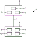
Fig. 1 shows schematically and exemplarily an embodiment of a power supply system 1 comprising a power supply device 2 and an electrical device 4. In this embodiment, the power sourcing equipment 2 is a PSE according to the PoE standard and the electrical device is a PD according to the PoE standard. The power supply apparatus 2 and the electric apparatus 4 are connected via an ethernet cable 3.
The power supply device 2 and the electrical device 4 are adapted to be operated in a classification mode, wherein a class of the power supply device 2 indicating an amount of power provided by the power supply device 2 in its operation mode and a class of the electrical device 4 indicating an amount of power on which the electrical device 4 is to be operated in its operation mode are determined. The power supply device 2 and the electrical device 4 are adapted such that in the classification mode, in a first phase, the power supply device 2 provides the electrical device 4 with one or several voltage pulses within a predefined voltage range and the electrical device 4 draws one or several classification current pulses to indicate a class of the electrical device 4, wherein the power supply device 2 measures the drawn one or several classification current pulses and determines the class of the electrical device 4 based on the measured drawn current. The power supply device 2 and the electrical device 4 are further adapted such that in the classification mode, in the second phase, the power supply device 2 provides one or several voltage pulses within a predefined voltage range to indicate to the electrical device 4 the classification of the power supply device 2, wherein the electrical device 4 measures the one or several voltage pulses and determines the classification of the power supply device 2 in dependence on the measured voltage pulses, i.e. preferentially based on the number of measured voltage pulses. The predefined classification voltage range is preferably 15.5V-20.5V.
Preferentially, the electrical device 4 is adapted to measure the voltage pulses provided by the power supply device 2 in a first phase and to determine the class of the power supply device 2 in dependence on the measured voltage pulses, wherein the power supply device 2 is adapted to not provide a voltage larger than a predefined threshold voltage at least for a predefined time after the first phase and before the second phase, wherein the electrical device 4 is adapted to reset the determination of the class of the power supply device 2 performed in the first phase if the electrical device 4 does not measure a voltage larger than the predefined threshold voltage at least for the predefined time. Thus, in the first and second phases, the electrical device 4 can act in the same way, i.e. it is not necessary to configure the electrical device 4 such that it behaves differently in the first and second phases. To reset the determination of the class of the power supply device 2 performed by the electrical device 4 in the first phase, the power supply device 2 may provide no voltage to the electrical device 4 for a predefined time or a voltage less than or equal to a predefined threshold voltage for a predefined time.
The power supply device 2 is adapted to provide voltage pulses within a predefined voltage range in a first phase until a classification current pulse sufficient for determining the class of the electrical device 4 has been measured. Thereby, it will be possible for the power providing device 2 to indicate an error class to the electrical device 4, but this is not a problem, since this determination of the class of the power providing device will be reset and the class of the power providing device will again be determined in the second phase.
The power supply device 2 and the electrical device 4 include an electrical device classification rule defining a class of the electrical device based on the classification current pulse and a power supply device classification rule defining a class of the power supply device based on the measured voltage pulse. The electrical device 4 is adapted to generate classification current pulses according to an electrical device classification rule to indicate the class of the electrical device 4, wherein the power sourcing device 2 is adapted to determine the class of the electrical device 4 in a first phase based on the electrical device classification rule and the measured classification current pulses. The power providing device 2 is adapted to provide voltage pulses within a predefined voltage range according to the power providing device classification rule in the second phase to indicate the class of the power providing device 2 to the electrical device 4, and the electrical device 4 is adapted to determine the class of the power providing device 2 based on the measured voltage pulses and the power providing device classification rule in the second phase.
The electrical device 4 and the power supply device 2 are each assigned to a type among a set of possible types, wherein the type of the power supply device 2 indicates the amount of power providable by the power supply device 2 in its operating mode, and the type of the electrical device 4 indicates the amount of power on which the electrical device is operable in its operating mode. Preferably, in the classification mode, not only the categories of the power supply apparatus 2 and the electrical apparatus 4 but also the types thereof are determined. In particular, the power supply device 2 and the electrical device 4 are preferentially adapted such that in the classification mode the electrical device 4 draws one or several classification current pulses in a first phase to indicate the class and type of the electrical device 4, wherein the power supply device 2 determines the class and type of the electrical device 4 based on the measured drawn classification current pulses. Furthermore, the power supply device 2 and the electrical device 4 are preferentially adapted such that in the classification mode, in the second phase the power supply device 2 provides one or several voltage pulses within a predefined voltage range to indicate the class and type of the power supply device 2 to the electrical device 4, wherein the electrical device 4 determines the class and type of the power supply device 2 depending on the measured voltage pulses.
The type of power supply equipment and the type of electrical equipment can be considered as containers for certain capabilities and general specifications. The power supply device classification rules may also comprise rules for defining the type of the power supply device in dependence on one or several voltage pulses provided by the power supply device within a predefined voltage range. Furthermore, the electrical device classification rules can also comprise rules defining the type of electrical device depending on the classification current pulses drawn. For example, the power supply equipment classification rules can define: the type of the power supply device is indicated by the duration of one or several voltage pulses within a predefined voltage range, while the class of the power supply device is indicated by the number of voltage pulses within the predefined voltage range. The electrical device classification rules can define: the type and class of electrical devices are defined by some sort of current pulse sequence. For example, the electrical device can be adapted to draw at least one of a set of five different numbers of classification current pulses numbered 0 to 4, wherein the sequences of classification current pulses can indicate the respective type and class of the respective electrical device. For example, the first sequence 4,4,0,4 may indicate "type 3" with a category indicating that the electrical device is to be operated on 30W in its operating mode, while the second sequence 4,4,1,4 may indicate "type 3" with a category indicating that the electrical device is to be operated on 45W in its operating mode.
The power supply device 2 may be able to provide different amounts of power in order to be operated in different categories, wherein the power supply device 2 can be adapted such that in the classification mode in the second phase the power supply device 2 provides one or several voltage pulses such that it indicates a category corresponding to the maximum amount of power providable by the power supply device 2, if the determined category of the electrical device 4 indicates a larger amount of power than the maximum amount of power providable by the power supply device 2. Accordingly, if the determined category of the power supply device indicates a smaller amount of power than the amount of power indicated with the category of the electrical device 4, the electrical device 4 can be adapted to be operated on the smaller amount of power provided by the power supply device 2 in its operation mode. Thus, the power supply apparatus 2 can give as much power as it can use for distribution even if that (power) is lower than that requested by the electrical apparatus 4.
For providing the voltage pulses in the classification mode and for providing the power in the operation mode, the power supply device 2 comprises a power supply 5. The power supply 5 may comprise an AC/DC converter for converting AC mains power received from a mains (mains) power supply to DC power to be supplied to the electrical device 4. However, the power source 5 can also be another type of power source for providing power to the electrical device 4. The power supply device 2 further comprises a current measurement unit 6 for measuring the current drawn by the electrical device 4 and a controller 7, wherein the controller 7 is for controlling the power supply device 2, in particular the power supply 5 and the current measurement unit 6, and for performing the determination process as if the type and class of the electrical device 4 is determined depending on the measured current.
The electrical device 4 comprises a voltage measuring unit 8 for measuring the voltage applied by the power supply device 2 to the electrical device 4 and a current drawing unit 9 for drawing some current to indicate the type and class of the electrical device 4 to the power supply device 2. In particular, the current drawing unit 9 comprises several resistors in order to draw certain specific classification current pulses. Electrical device 4 further comprises an electrical consumer (electrical consumer) like a lighting unit that consumes the power provided by power supply device 2 when power supply device 2 and electrical device 4 are in their operating modes, and a controller 10 for controlling electrical device 4, in particular voltage measurement unit 8, current drawing unit 9 and electrical consumer 11. The controller 10 is further adapted to perform the determination as to the type and class of the power supply device 2 based on the measured voltage pulses.
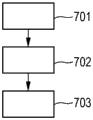
In the following, an embodiment of a control method for controlling the power supply system 1 will be exemplarily described with reference to a flowchart shown in fig. 2.
After the electrical device 4 has been connected to the power sourcing equipment 2 by using the ethernet cable 3, in a first phase of the classification mode, the power sourcing equipment 2 provides one or several voltage pulses within a predefined voltage range to the electrical device 4 and the electrical device 4 draws one or several classification current pulses to indicate the class of the electrical device 4, step 701. Furthermore, in step 701, the power supply device 2 measures one or several classification current pulses drawn and determines the class of the electrical device 4 based on the measured classification current pulses drawn, while the electrical device 4 measures the voltage pulses provided by the power supply device 2 and determines the class of the power supply device 2 depending on the measured voltage pulses.
In step 702, power supply apparatus 2 supplies electrical device 4 with a voltage smaller than a predefined threshold voltage or with no voltage for a predefined time, in order to indicate to electrical device 4: it should reset the determination of the class of the power supply apparatus 2 performed in step 701. Further, the electrical device 4 measures: a voltage smaller than the predefined threshold voltage for the predefined time or no voltage has been applied to the electrical device 4 and the electrical device 4 resets the determination of the class of the power providing device 4 performed in step 701.
In step 703, in a second phase the power sourcing equipment 2 provides one or several voltage pulses within a predefined voltage range to indicate the class of the power sourcing equipment 2 to the electrical device 4, wherein the electrical device 4 measures the one or several voltage pulses and determines the class of the power sourcing equipment 2 depending on the measured voltage pulses.
The above-described classification procedure may be implemented in a successor of the PoE standard 802.3at like 802.3bt or in another PoE standard. In particular, the classification procedure described above can be used to extend the two-event classification mechanism of the PoE standard 802.3 at.
In the PoE standard 802.3bt, the power sourcing equipment classification rules can be defined to correspond to table 1 below:
| event counting | Power supply | Type (B) |
| 1 |
15W | Type (2): 1,2,3,4 |
| 2 |
30W | Type (2): 2,3,4 |
| 3 |
30W | Type (2): 3,4 |
| 4 |
45W,60W | Type (2): 3,4 |
| 5 event | 75W,90W | Type (2): 4 |
The types mentioned in table 1 exemplarily indicate types of power supply apparatuses having a capability to supply the respective amounts of power. The events mentioned in table 1 relate to voltage pulses generated by the power supply device, i.e. the number of classification events, to indicate their class.
The types and classes of electrical devices and electrical device classification rules that can be implemented in the PoE standard 802.3bt will be exemplarily described below.
For example, a type 1 PD may indicate its class by: if it requests 15W, then a classification current of 0 is drawn; if it requests 4W, a classification current of 1 is drawn; if it requests 7W, then a classification current of 2 is drawn; and if it requests 15W, then a classification current of 3 is drawn, where it does not preferentially discern anything beyond a single classification event. If presented with multiple classification events, the PD will repeat the same classification current for each event. A type 2 PD may indicate its class by drawing a classification current 4 on each classification event. If the PD sees only a single classification event, it will treat the PSE as a type 1 PSE and will then only be allowed to draw maximum type 1 power. If the PD sees a second classification event, it will distinguish the PSE as a type 2 PSE and understand this as being allowed to draw maximum type 2 power. Classification events beyond the second (classification event) are not meaningful for type 2 PDs.
The electrical device classification rules of PoE standard 802.3bt may also define type 3 PD and type 4 PD. For these PD types, the generation of the classification current pulses may depend on the desired power. For example, if a PD wants to have 15W or less, it may show type 1 PD behavior for classification. The PD may then also check the type of the PSE based on the duration of the first voltage pulse, wherein a relatively long duration within a predefined duration range would indicate that the PSE is a type 3 or type 4 PSE, while a smaller duration would indicate that the PSE is a type 1 or type 2 PSE. If the PD wants to have 30W, it may show a type 2 PD behavior, wherein also in this case the PD may check the type of the PSE based on the duration of the first voltage pulse. Also, if the PD wants to have more than 30W, the PD may generate a classification current 4 for the first two classification events in order to ensure backward compatibility with type 1 and type 2 PSEs, while for the subsequent classification events the PD may switch to a different classification current, e.g., as described in table 2 below:
| current response to classification events | Type (B) | Requested |
| 4,4,4 | |
|
| 4,4,0,0 | |
|
| 4,4,1,1 | |
|
| 4,4,2,2,2 | |
|
| 4,4,3,3,3 | |
90W |
The problem of mutual identification exists if the power sourcing equipment classification rules and the electrical equipment classification rules are used in this way according to the PoE 802.3bt standard. In particular, the PSE will not always be able to distinguish between certain PDs. Hereinafter, a "blind spot" will exist.
A type 3 PSE and a type 4 PSE will not be able to distinguish type 2 PD, type 3 PD which respond with class current 4 from each other, wherein the type 3 PD operates at a power of 30W in its operating mode and shows type 2 PD behavior for the class, whereas the type 3 PD operates at a power of 45W, 60W, 75W or 90W if the PSE has only 15W or 30W available, i.e. if the PSE provides only one or two voltage pulses. Furthermore, a type 3 PSE or a type 4 PSE will not be able to distinguish between a type 1 PD generating a classification current of 0, 1, 2 or 3 and a type 3 PD generating a classification current of 0, 1, 2 or 3.
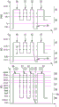
These mutually identified issues are described in more detail below with reference to FIG. 3, where the problematic combinations in FIG. 3 are highlighted with a box 20 … 23.
A solution to these mutual identification problems, including the decoupling of the classification process to two stages described above, will be described below with reference to fig. 4.
In the situation described above with reference to blocks 20 and 22 shown in fig. 3, a type 3 PSE is able to generate more than a single classification event without risking that the PD will consume more than 15W. Thus, in a situation where the response to the first classification event is a classification current of 0, 1, 2 or 3, the type 3 PSE is able to generate as many classification events as are needed to determine the type and class of the respective PD. If a type 3 PD with a required power of maximum 15W exhibits a class current of 4 from the third class event (onward), the type 3 PSE is able to distinguish this type 3 PD from a type 1 PD which would generate class currents 0, 1, 2 or 3 for each class event. This solves the mutual identification problem described above with reference to blocks 20 and 22 shown in fig. 3. To solve the mutual identification problem described above with reference to block 23, the classification code for type 3 PDs requiring 30W can be changed from 4,4,4 to 4,4,0 as defined in table 2. Further, in an embodiment, one of the categories indicating 45W, 60W, 75W, and 90W may be removed, and a unique category code may be introduced to distinguish a type 2 PD operating on 30W from a type 3 PD or a type 4 PD operating on 30W. This allows a type 3 PSE with a power budget equal to or greater than 30W to distinguish a type 2 PD from a type 3 PD with a 30W power requirement.
To solve the problem described above with reference to block 21, the above-described decoupling of the classification process into two stages can be used. In particular, part of this problem may be described by asking how a type 3 PSE with a power budget of 15W can distinguish between a type 2 PD and a type 3 PD with a power demand of 30W. As described above, if the classification current code of the type 3 PD having the power demand of 30W is changed from 4,4,4 to 4,4,0 in table 2, the two PDs have different classification current codes, i.e., 4,4,4 for the type 2 PD and 4,4,0 for the type 3 PD having the power demand of 30W. A type 3 PSE with a power budget of 15W cannot find this without generating three classification events. However, if it generates three classification events, it will have committed to 30W of available power, but only 15W of available. The problem thus solved with the decoupling of the classification process to two stages described above is: the PSE will need to provide more classification events in order to identify the PDs it will be allowed to generate because the number of classification events indicates the power supplied by the PSE and the PSE will not be allowed to supply more power than it really can provide.
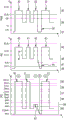
In an embodiment, an ethernet cable connecting a PSE and a PD may be considered a pathway connecting a Power Interface (PI) of the PSE with a PI of the PD, where the PI is an electrical interface on a respective device side of a respective connector, and where a connector contact (contact) may be part of the pathway. In an embodiment, a PSE, which may be a type 3 PSE supplying 15W, generates as many events as are needed to learn the nature of the connected PD. At this point, it has committed the power it does not have, but the PD has not yet been powered. The PSE then in turn causes the voltage on the PSE PI to drop below a predefined threshold voltage, which may be named Vreset(for spatial reasons the threshold voltage is named V in FIG. 4r). It can be adapted to do so by turning off internal circuitry that generates classification events, i.e. voltage pulses for classifying the PSE, and may also generate other voltages like flag and detection voltages. The PSE then waits a predefined time, which may be named TresetAnd to ensure that the previous determination of the class of the power supply device is reset, i.e. for example the classification state machine of the PD has been reset. The PD has now "forgotten" the false commitment of power. The PSE then optionally continues with the second phase after the detection phase has been performed, but this time itOnly the number of classification events corresponding to the amount of power it can actually supply is generated. This will be described in more detail below with reference to fig. 5 and 6.
Fig. 5 exemplarily illustrates the generation of three classification events 30, 31, 32 within a predefined voltage range 35 in a first phase of a classification process with a type 3 PSE supplying 15W, wherein a connected type 2 PD responds with a classification current 50, 51, 52 being a classification current 4. After this first phase, the PSE provides a voltage within the class reset voltage range 37, wherein this voltage is smaller than the predefined threshold voltage for the predefined time. This is indicated in fig. 5 with reference numeral 34. The PD measures this small voltage within the class reset voltage range 48 and resets all previous determinations of the class of the PSE. Subsequently, the PSE provides a further classification event 33 in the second phase to indicate its class to the PD, whereby the PD determines that the PSE supplies 15W in the second phase because of the single classification event 33.
In fig. 5, reference numeral 36 indicates a marker event voltage range on the PSE, reference numeral 45 indicates a class event voltage range on the PD, reference numeral 46 indicates a marker event voltage range on the PD, reference numeral 47 indicates a class reset threshold on the PD, and reference numeral 48 indicates a class reset voltage range. Further, reference numerals 55 to 59 indicate classification current ranges 4, 3, 2, 1, 0, respectively, and reference numeral 60 indicates a mark current range. The marking current range serves to distinguish the different current pulses from one another, i.e. between these current pulses the current is reduced to a marking current I in the marking current range 60mark。
Fig. 6 shows schematically and exemplarily a situation in which a type 3 PSE supplying 15W before lowering the voltage to a value smaller than a predefined threshold voltage such that the voltage is within the class reset voltage range 37 generates three class events 30, 31, 32 in a first phase. In this example a PD requiring 30W or more of type 3 PD measures the corresponding voltage pulse 40, 41, 42 within the classification event voltage range 45 and also measures the voltage drop 44 within the classification reset voltage range 48 below the predefined threshold voltage. In response to the voltage pulses 30, 31, 32, the PD draws a classification current 50, 51, 61 within a classification current range 4 (reference numeral 55), 4 (reference numeral 55) and 0 (reference numeral 59) in order to provide a classification current sequence 4,4, 0. In response to the measured voltage drop 44, the PD resets all previous determinations of the PSE class. In the second phase the PSE generates a second classification event 33, i.e. a single voltage pulse 33, which results in a voltage pulse 43 on the PD measured within a classification event voltage range 45, whereby the PD determines that the PSE will supply 15W.
In an embodiment, the PSE does not generate more classification events, i.e., voltage pulses, if the power being requested by the PD does not guarantee it. For example, a 90W PSE may signal (signal) its 90W capabilities by generating five classification events according to table 1. However, if a 45W PD is connected, the PSE is aware of this fact by the third classification event (4, 4, 0) in view of table 2. The PSE will then generate a fourth classification event to indicate that it is giving a 45W request, but will not generate a fifth classification event.
The PD and the PSE are preferably adapted such that the PD is at least able to distinguish between its own type of PSE and the type and class of the lower type PSE, i.e. the amount of power supplied. It is preferable that: all mechanisms are set up in a way that guarantees backward compatibility. For example, from the perspective of a type 2 PD, a type 4 PSE may look like a type 2 PSE. In particular, type 3 or type 4 PSEs may provide a longer first classification event than type 1 PSEs and type 2 PSEs. This longer event may be ignored by type 1 and type 2 PDs, but may be detected by type 3 or type 4 PDs, thus identifying the PSE as a type 3 or type 4 PSE.
A two-phase classification procedure with an intermediate reset step may be employed in the PoE standard 802.3bt, where the PSE may add the sequence of classification events shown in fig. 5 and 6 to the PSE state diagram. In an implementation aspect (wise), to reset the PD halfway through the classification process, for example, the PSE may connect the return conductor of the PI to the positive rail (positive rail), resulting in a positive rail for at least TResetForced to be lower than VResetIs applied across PI. It is also possible that the PSE becomes a high impedance state, i.e. the state it was in when idle. Over PoE standard 802.3Ensuring of at, type 2 PD will utilize at least ImarkThe PD PI is self-discharged until the PD has been reset. For type 1 PDs, another approach may be used, i.e. for example, to distinguish between a) type 1 PDs requesting 4W, 7W or 15W by drawing one of the classification currents 0-3 in response to a voltage pulse provided by the PSE and b) type 3 PDs requesting 4W, 7W or 15W by drawing one of the classification currents 0-3 in response to a voltage pulse provided by the PSE, the type 3 PDs may be configured to respond to a third voltage pulse and/or a later voltage pulse, e.g. provided by the PSE, with a classification current of 4 or a higher numbered classification current. Type 1 PDs will simply repeat the corresponding classification current 0, 1, 2 or 3.
In an embodiment, the PSE is adapted such that the reset method is not applied to type 1 PDs, but only to PDs having another type. The PSE preferably performs the following functions: detecting the PD over the channel, i.e. over one or several ethernet cables; determining the amount of power requested by the battery; and applying a voltage to the channel, if applicable. The PSE is preferably further adapted to monitor the voltage and current and maintain the voltage as long as there is no overload condition or as long as the corresponding PD is still connected. The respective PD may be adapted to present a valid detection signature in the detection mode, which allows the PSE to detect the PD by means of the channel, present one or several valid classification current pulses while performing the classification process in order to indicate to the PSE the requested amount of power, and enable the load, i.e. the load of the PD, once the PSE has been given power in its operation mode.
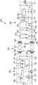
Fig. 7 schematically and exemplarily shows an embodiment of an implementation of a power supply system, wherein the power supply system comprises a PSE as power supply device and a PD as electrical device. The power supply system 601 includes a PSE 602, a PD 604, and a middle channel 603. In a first detection process, which may also be considered an identification process, the PSE 602 may impose a voltage and/or current on the PI that is within a detection voltage range, which may be a range from 2.8V to 10V. The PSE 602 is adapted to read a valid detection signature over a predefined resistance range, which may be from 19k Ω (kilo-ohms) to 26.5k Ω, where the PSE 602 uses the internal voltage source 103 and the internal current source 102 for this purpose in this embodiment. The meters 104, 105 are used to check the PI impedance. The PD 604 is adapted to present an effective detection resistance to the PSE 602, wherein the PD 604 may use optionally switchable impedances 502, 408 for this purpose. During the classification process, PSE 602 generates one or several classification events, i.e. voltage pulses in a classification voltage range, which may be from 15.5V to 20.5V, wherein also for generating the one or several classification events an internal voltage source 103 may be used. The current drawn by the PD 604 can be measured using the internal ammeter 105. The class will then be determined by the PSE controller 100 based on the measured current draw. The PSE controller 100 is also adapted to control different components of the PSE 602. The PD 604 is adapted to draw a classification current during a classification event, wherein it preferentially uses the switchable resistance or resistances 501, 409. In particular, if 605 PD (PD 605) is a type 3 or type 4 PD, PD 604 may use different classification currents depending on the event count. In particular, during the classification process, the PSE 602 generates as many classification events as are needed to determine the type and class of the PD 604 in the first phase, whereby the PSE 602 provides zero voltage or a non-zero voltage less than a predefined threshold voltage for a predefined time in order to reset the determination of the class and type of the PSE 602 by the PD 604, which has been determined by measuring the voltage pulses with the voltage measurement unit 500 and by using the PD controller 503 during the first phase. After the previous determination of the class and type of the PSE 602 has been reset, the PSE 602 only applies to the PSE PI in the second phase the number of classification events that are needed to indicate the type and class of the PSE 602 to the PD 604.
If the PSE 602 decides to give power to the PD 604, after successful identification and classification it will apply the corresponding voltage to the PSE PI by using the voltage 202 by conducting hot-swap 200 conduction. Initially, it is preferred that it uses the current sensing means 201, 101 to control the maximum current through the PSE PI. The PD 604 is preferentially adapted to respond to an applied voltage exceeding a predefined further threshold voltage by opening (open) its own hot swap 410 and to provide power to the load 412.
In this example, the PSE 602 includes a decoupling capacitor 203, and the intermediate channel 603 includes ethernet transformers 204, 205, 400, 401. Power is coupled in (manifold in) via the center tap, with data entering through the transformer ends that are not connected in fig. 7. The voltage is carried (carry) as a common mode on the pair line (pair), which is not visible to the data part. The intermediate channel 603 further comprises an 8P8C connector 300 and eight conductors 301, 302 in four twisted pairs, of which only two are shown in fig. 7. To provide a polarity insensitive PD 604, full bridge rectifiers 402, 403, 404, 405 using diodes and MOSFETs are used immediately after the ethernet transformers 400, 401. The PD 604 further includes an input capacitor 406, which may have a capacitance of up to 100nF (nano farads), an optional Zener diode 407 for protecting the PD 604 from voltages higher than desired, and a bulk capacitor 411, which may have a capacitance of minimum 5 μ F (micro farads).
Other variations to the disclosed embodiments can be understood and effected by those skilled in the art in practicing the claimed invention, from a study of the drawings, the disclosure, and the appended claims.
In the claims, the word "comprising" does not exclude other elements or steps, and the indefinite article "a" or "an" does not exclude a plurality.
A single unit or device may fulfill the functions of several items recited in the claims. The mere fact that certain measures are recited in mutually different dependent claims does not indicate that a combination of these measures cannot be used to advantage.
The process performed by one or several units or devices, like the determination of the class and type of the power supply device and/or the electrical device, can be performed by any other number of units or devices. The processes and/or the control of the power supply system according to the control method can be implemented as program code means of a computer program and/or as dedicated hardware. In particular, the control of the power supply system according to the control method can be implemented in the power supply device and in the electrical device, wherein the implementations in these devices cooperate to control the power supply system according to the control method.
A computer program may be stored and/or distributed on a suitable medium, such as an optical storage medium or a solid-state medium supplied together with or as part of other hardware, but may also be distributed in other forms, such as via the internet or other wired or wireless telecommunication systems.
Any reference signs in the claims shall not be construed as limiting the scope.
The present invention relates to a power supply system comprising power supply equipment like a PSE and electrical equipment like a PD. In the classification mode, in a first phase the power providing device provides one or several voltage pulses and the electrical device draws one or several classification current pulses to indicate the class of the electrical device, wherein in a second phase the power providing device provides one or several voltage pulses to indicate the class of the power providing device. Thus, the indication of the class of the electrical device and the class of the power supply device is decoupled into two different phases, which can lead to an improved mutual classification process.
Claims (13)
1. A power supply device to be used in a power supply system, characterized in that the power supply device (2;602) is adapted to be operated in a two-stage classification mode, wherein a class of the power supply device (2;602) indicative of an amount of power to be supplied by the power supply device (2;602) in the operation mode and a class of the electrical device (4;604) of the power supply system indicative of an amount of power on which the electrical device (4;604) is to be operated in the operation mode are determined, wherein the power supply device (2;602) is adapted such that in the classification mode:
in a first phase, the power supply device (2;602) provides one or several voltage pulses within a predefined voltage range to the electrical device (4;604), measures one or several classification current pulses drawn by the electrical device (4;604) and determines a class of the electrical device (4;604) based on the measured drawn classification current pulses,
in a second phase, the power providing device (2;602) provides one or several voltage pulses within a predefined voltage range to indicate to the electrical device (4;604) the class of the power providing device (2;602),
wherein the determination of the class of the electrical device in the first phase and the determination of the class of the power supply device in the second phase are decoupled.
2. A power supply system comprising a power supply device (2;602) according to claim 1 and an electrical device (4;604), wherein the power supply device (2;602) and the electrical device (4;604) are adapted to be operated in a two-stage classification mode, wherein a class of the power supply device (2;602) indicative of an amount of power provided by the power supply device (2;602) in the operation mode and a class of the electrical device (4;604) indicative of an amount of power on which the electrical device (4;604) is to be operated in the operation mode are determined, wherein the power supply device (2;602) and the electrical device (4;604) are adapted such that in the classification mode:
in a first phase, the power sourcing device (2;602) provides one or several voltage pulses within a predefined voltage range to the electrical device (4;604), and the electrical device (4;604) draws one or several classification current pulses to indicate a class of the electrical device (4;604), wherein the power sourcing device (2;602) measures the drawn one or several classification current pulses and determines the class of the electrical device (4;604) based on the measured drawn classification current pulses,
in a second phase, the power supply device (2;602) provides one or several voltage pulses within a predefined voltage range to indicate to the electrical device (4;604) the class of the power supply device (2;602), wherein the electrical device (4;604) measures the one or several voltage pulses and determines the class of the power supply device (2;602) depending on the measured voltage pulses,
wherein the determination of the class of the electrical device in the first phase and the determination of the class of the power supply device in the second phase are decoupled.
3. The power supply system according to claim 2, wherein the electrical device (4;604) is adapted to measure the voltage pulses provided by the power supply device (2;602) in a first phase and to determine the class of the power supply device (2;602) depending on the measured voltage pulses, wherein the power supply device (2;602) is adapted to not provide a voltage larger than a predefined threshold voltage at least for a predefined time after the first phase and before the second phase, wherein the electrical device (4;604) is adapted to: the determination of the class of the power supply device (2;602) is reset if the electrical device (4;604) does not measure a voltage greater than a predefined threshold voltage at least for a predefined time.
4. The power supply system according to claim 2, wherein the power supply device (2;602) is adapted to provide voltage pulses within a predefined voltage range until a classification current pulse sufficient for determining the class of the electrical device (4;604) has been measured.
5. The power supply system of claim 2, wherein the power supply device (2;602) is capable of providing in the first phase a voltage pulse within a predefined voltage range indicating a class not corresponding to the power supply device (2;602) is to provide in its operational mode.
6. The power supply system of claim 2, wherein the power supply device (2;602) is capable of providing different amounts of power in order to be operated in different categories, wherein the power supply device (2;602) is adapted to provide one or several voltage pulses in the second phase in the classification mode such that it indicates the category of the power supply device corresponding to the category of the electrical device (4;604) that has been determined in the first phase.
7. The power supply system of claim 2, wherein the power supply device (2;602) is capable of providing different amounts of power in order to be operated in different categories, wherein the power supply device (2;602) is adapted to provide one or several voltage pulses in the second phase in the classification mode, such that if the category of the electrical device (4;604) determined in the first phase indicates an amount of power which is larger than the amount of power maximally providable by the power supply device (2;602), it indicates a category corresponding to the maximum amount of power providable by the power supply device (2; 602).
8. The power supply system according to claim 2, wherein the electrical device (4;604) is adapted to: if the determined class of the power providing device (2;602) indicates a smaller amount of power than the amount of power indicated by the class of the electrical device (4;604), is operated on the smaller amount of power provided by the power providing device (2;602) in its operation mode.
9. The power supply system of claim 2, wherein the electrical device (4;604) and the power supply device (2;602) are each assigned to a type among a set of possible types, wherein the type of the power supply device indicates an amount of power providable by the power supply device in its operating mode, and the type of the electrical device indicates an amount of power on which the electrical device is operable in its operating mode, wherein the power supply device (2;602) and the electrical device (4;604) are adapted such that in the classification mode:
in a first phase, the electrical device (4;604) draws one or several classification current pulses to indicate the class and type of the electrical device (4;604), wherein the power sourcing equipment (2;602) determines the class and type of the electrical device (4;604) based on the measured draw classification current pulses, and
in a second phase, the power supply device (2;602) provides one or several voltage pulses within a predefined voltage range to indicate to the electrical device (4;604) the class and type of the power supply device (2;602), wherein the electrical device (4;604) determines the class and type of the power supply device (2;602) depending on the measured voltage pulses.
10. The power supply system of claim 2, wherein the electrical device (4;604) is assigned to a type among a set of possible types, wherein the type of the electrical device indicates an amount of power on which the electrical device is operable in its operating mode, wherein the set of possible types of the electrical device comprises a first type indicating one or several first amounts of power on which the electrical device is operable in its operating mode and a second type indicating one or several second amounts of power on which the electrical device is operable in its operating mode, wherein at least one of the one or several first amounts of power is equal to at least one of the one or several second amounts of power, and the power supply device (2;602) and the electrical device (4;604) are adapted such that in the classification mode, in a first phase, the electrical device (4;604) draws one or several classification current pulses to indicate the class and the type of the electrical device (4;604), wherein the power providing device (2;602) determines the class and type of the electrical device (4;604) based on the measured draw classification current pulses, even if the electrical device is of the first type or the second type and is to be operated in its operation mode on an amount of power on which the electrical device of the first type is operable in its operation mode and the electrical device of the second type is operable in its operation mode.
11. An electrical device to be used in a power supply system according to claim 2, characterized in that the electrical device (4;604) is adapted to be operated in a two-stage classification mode, wherein a class of the power supply device (2;602) of the power supply system indicative of an amount of power provided by the power supply device (2;602) in the operation mode and a class of the electrical device (4;604) indicative of an amount of power on which the electrical device (4;604) is to be operated in the operation mode are determined, wherein the electrical device (4;604) is adapted such that in the classification mode:
in a first phase, the electrical device (4;604) draws one or several classification current pulses to indicate the class of the electrical device (4;604), while the power sourcing equipment (2;602) provides one or several voltage pulses within a predefined voltage range to the electrical device (4;604),
in a second phase, the electrical device (4;604) measures one or several voltage pulses provided by the power supply device (2;602) and determines the class of the power supply device (2;602) depending on the measured voltage pulses,
wherein the determination of the class of the electrical device in the first phase and the determination of the class of the power supply device in the second phase are decoupled.
12. A control method for controlling a power supply system according to claim 2, characterized in that the control method is adapted such that in a two-stage classification mode:
in a first phase, the power sourcing device (2;602) provides one or several voltage pulses within a predefined voltage range to the electrical device (4;604), and the electrical device (4;604) draws one or several classification current pulses to indicate a class of the electrical device (4;604), wherein the power sourcing device (2;602) measures the drawn one or several classification current pulses and determines the class of the electrical device (4;604) based on the measured drawn classification current pulses,
in a second phase, the power supply device (2;602) provides one or several voltage pulses within a predefined voltage range to indicate to the electrical device (4;604) the class of the power supply device (2;602), wherein the electrical device (4;604) measures the one or several voltage pulses and determines the class of the power supply device (2;602) depending on the measured voltage pulses,
wherein the determination of the class of the electrical device in the first phase and the determination of the class of the power supply device in the second phase are decoupled.
13. A storage medium for storing a computer program adapted to control a power supply system according to claim 2, the computer program comprising program code means for causing the power supply system to carry out the control method according to claim 12, when the computer program is run on the power supply system.
Applications Claiming Priority (3)
| Application Number | Priority Date | Filing Date | Title |
|---|---|---|---|
| EP15167792 | 2015-05-15 | ||
| EP15167792.9 | 2015-05-15 | ||
| PCT/EP2016/059592 WO2016184661A1 (en) | 2015-05-15 | 2016-04-29 | Power providing system |
Publications (2)
| Publication Number | Publication Date |
|---|---|
| CN107864693A CN107864693A (en) | 2018-03-30 |
| CN107864693B true CN107864693B (en) | 2020-12-18 |
Family
ID=53181116
Family Applications (1)
| Application Number | Title | Priority Date | Filing Date |
|---|---|---|---|
| CN201680028257.5A Active CN107864693B (en) | 2015-05-15 | 2016-04-29 | Power supply system |
Country Status (5)
| Country | Link |
|---|---|
| US (1) | US10855479B2 (en) |
| EP (1) | EP3295607B1 (en) |
| JP (1) | JP6925281B2 (en) |
| CN (1) | CN107864693B (en) |
| WO (1) | WO2016184661A1 (en) |
Families Citing this family (11)
| Publication number | Priority date | Publication date | Assignee | Title |
|---|---|---|---|---|
| US9874930B2 (en) * | 2015-09-03 | 2018-01-23 | Cisco Technology, Inc. | Selection of power in power over ethernet systems |
| US11003152B2 (en) * | 2016-09-23 | 2021-05-11 | Signify Holding B.V. | Building automation system with servicing beacon |
| US11082243B2 (en) * | 2017-04-24 | 2021-08-03 | Signify Holding B.V. | Power management device for immediate start-up during power negotiation |
| GB2568259B (en) * | 2017-11-08 | 2020-04-15 | Canon Kk | Method and device for generating a voltage drop pulse |
| US11095465B2 (en) | 2017-11-13 | 2021-08-17 | Signify Holding B.V. | Control of power delivery to a DC-powered device |
| EP3741084B1 (en) * | 2018-01-16 | 2022-07-13 | Signify Holding B.V. | Simple power over ethernet data transmission protocol |
| CN110554725B (en) * | 2018-05-30 | 2021-02-23 | 华为技术有限公司 | Power receiving equipment for power over Ethernet |
| CN111555937B (en) * | 2020-04-27 | 2022-02-25 | 普联技术有限公司 | PSE port type detection system, method, device and control module |
| CN113125877B (en) * | 2021-03-02 | 2022-12-06 | 华为技术有限公司 | PD detection equipment for powered device |
| EP4308084A2 (en) | 2021-03-19 | 2024-01-24 | Pacira Pharmaceuticals, Inc. | Treatment of pain in pediatric patients by administration of sustained-release liposomal anesthetic compositions |
| CN115460113A (en) * | 2022-07-29 | 2022-12-09 | 深圳市智微智能科技股份有限公司 | POE switch protocol detection method and load instrument |
Citations (4)
| Publication number | Priority date | Publication date | Assignee | Title |
|---|---|---|---|---|
| CN101218809A (en) * | 2005-08-30 | 2008-07-09 | 思科技术公司 | Low-power Ethernet device |
| CN101305546A (en) * | 2005-11-10 | 2008-11-12 | 美高森美股份有限公司-模拟混合信号集团有限公司 | Enhanced classification for power over ethernet |
| EP2816759A1 (en) * | 2013-06-18 | 2014-12-24 | Linear Technology Corporation | Power over ethernet on data pairs and spare pairs |
| US8972757B2 (en) * | 2004-11-03 | 2015-03-03 | Cisco Technology, Inc. | Powered device classification in a wired data telecommunications network |
Family Cites Families (5)
| Publication number | Priority date | Publication date | Assignee | Title |
|---|---|---|---|---|
| US20060212724A1 (en) * | 2005-03-15 | 2006-09-21 | Dwelley David M | System and method for supporting operations of advanced power over ethernet system |
| EP1980050B1 (en) * | 2006-01-17 | 2014-12-17 | Broadcom Corporation | Power over ethernet controller integrated circuit architecture |
| JP2009106127A (en) * | 2007-10-25 | 2009-05-14 | Sharp Corp | PoE POWER RECEIVING DEVICE |
| US9164558B2 (en) * | 2013-02-14 | 2015-10-20 | Cisco Technology, Inc. | Automatic classification change in power over ethernet device |
| WO2015028210A1 (en) * | 2013-08-27 | 2015-03-05 | Koninklijke Philips N.V. | Power distribution system |
-
2016
- 2016-04-29 CN CN201680028257.5A patent/CN107864693B/en active Active
- 2016-04-29 US US15/574,355 patent/US10855479B2/en active Active
- 2016-04-29 JP JP2017559551A patent/JP6925281B2/en active Active
- 2016-04-29 EP EP16722573.9A patent/EP3295607B1/en active Active
- 2016-04-29 WO PCT/EP2016/059592 patent/WO2016184661A1/en active Application Filing
Patent Citations (4)
| Publication number | Priority date | Publication date | Assignee | Title |
|---|---|---|---|---|
| US8972757B2 (en) * | 2004-11-03 | 2015-03-03 | Cisco Technology, Inc. | Powered device classification in a wired data telecommunications network |
| CN101218809A (en) * | 2005-08-30 | 2008-07-09 | 思科技术公司 | Low-power Ethernet device |
| CN101305546A (en) * | 2005-11-10 | 2008-11-12 | 美高森美股份有限公司-模拟混合信号集团有限公司 | Enhanced classification for power over ethernet |
| EP2816759A1 (en) * | 2013-06-18 | 2014-12-24 | Linear Technology Corporation | Power over ethernet on data pairs and spare pairs |
Non-Patent Citations (2)
| Title |
|---|
| Extended Classification Using Ping-Pong Scheme;MARTIN PATOKA;《UR:http:// www.ieee802.orq/3/at/public/nov》;20051114;全文 * |
| IEEE P802 .3bt Mutual Power over Ethernet;David Abramson;《UR:http:// www.ieee802.org/3/bt/public/sep》;20140919;全文 * |
Also Published As
| Publication number | Publication date |
|---|---|
| US20180139063A1 (en) | 2018-05-17 |
| CN107864693A (en) | 2018-03-30 |
| JP6925281B2 (en) | 2021-08-25 |
| EP3295607B1 (en) | 2018-09-12 |
| WO2016184661A1 (en) | 2016-11-24 |
| US10855479B2 (en) | 2020-12-01 |
| JP2018522326A (en) | 2018-08-09 |
| EP3295607A1 (en) | 2018-03-21 |
Similar Documents
| Publication | Publication Date | Title |
|---|---|---|
| CN107864693B (en) | Power supply system | |
| US10261477B2 (en) | Detection and classification scheme for power over Ethernet system | |
| US9634844B2 (en) | Detection scheme for four wire pair Power Over Ethernet system | |
| US20150355697A1 (en) | Circuit for indicating power level over a communication interface | |
| JP4624430B2 (en) | Detection of legacy power-receiving equipment in Power over Ethernet (registered trademark) system | |
| JP4485576B2 (en) | Analog power management in Power over Ethernet system | |
| EP3197091B1 (en) | Power distribution system | |
| CN111478777B (en) | Power over Ethernet powered device automatically maintains power characteristics | |
| US20040260794A1 (en) | Pre-detection of powered devices | |
| US20170214533A1 (en) | Power Source Equipment and Power Supplying Method for Power over Ethernet system | |
| RU2716747C2 (en) | Forced bulk capacitor discharge in powered device | |
| US20170228006A1 (en) | Inspection device and method for multiple powered devices in a power over ethernet system | |
| US8587264B2 (en) | System, method and apparatus to automatically detect a type of a variable output DC power source | |
| JP6592618B2 (en) | Determination of power supply mode for DC power receiving device | |
| US10447488B2 (en) | Device and method for detecting powered devices connected to a power source equipment in a power over ethernet system | |
| TWI762923B (en) | Power sourcing equipment and connection checking method |
Legal Events
| Date | Code | Title | Description |
|---|---|---|---|
| PB01 | Publication | ||
| PB01 | Publication | ||
| SE01 | Entry into force of request for substantive examination | ||
| SE01 | Entry into force of request for substantive examination | ||
| GR01 | Patent grant | ||
| GR01 | Patent grant | ||
| CP03 | Change of name, title or address |
Address after: Eindhoven Patentee after: Signify Holdings Ltd. Address before: Eindhoven, the Netherlands Patentee before: PHILIPS LIGHTING HOLDING B.V. |
|
| CP03 | Change of name, title or address |