CN107725994B - Installation and adjustment component of projection screen and projection screen - Google Patents
Installation and adjustment component of projection screen and projection screen Download PDFInfo
- Publication number
- CN107725994B CN107725994B CN201711144577.XA CN201711144577A CN107725994B CN 107725994 B CN107725994 B CN 107725994B CN 201711144577 A CN201711144577 A CN 201711144577A CN 107725994 B CN107725994 B CN 107725994B
- Authority
- CN
- China
- Prior art keywords
- projection screen
- adjustment
- frame
- adjusting
- assembly
- Prior art date
- Legal status (The legal status is an assumption and is not a legal conclusion. Google has not performed a legal analysis and makes no representation as to the accuracy of the status listed.)
- Active
Links
Images


Classifications
-
- F—MECHANICAL ENGINEERING; LIGHTING; HEATING; WEAPONS; BLASTING
- F16—ENGINEERING ELEMENTS AND UNITS; GENERAL MEASURES FOR PRODUCING AND MAINTAINING EFFECTIVE FUNCTIONING OF MACHINES OR INSTALLATIONS; THERMAL INSULATION IN GENERAL
- F16M—FRAMES, CASINGS OR BEDS OF ENGINES, MACHINES OR APPARATUS, NOT SPECIFIC TO ENGINES, MACHINES OR APPARATUS PROVIDED FOR ELSEWHERE; STANDS; SUPPORTS
- F16M11/00—Stands or trestles as supports for apparatus or articles placed thereon ; Stands for scientific apparatus such as gravitational force meters
- F16M11/02—Heads
- F16M11/04—Means for attachment of apparatus; Means allowing adjustment of the apparatus relatively to the stand
- F16M11/043—Allowing translations
- F16M11/046—Allowing translations adapted to upward-downward translation movement
-
- G—PHYSICS
- G03—PHOTOGRAPHY; CINEMATOGRAPHY; ANALOGOUS TECHNIQUES USING WAVES OTHER THAN OPTICAL WAVES; ELECTROGRAPHY; HOLOGRAPHY
- G03B—APPARATUS OR ARRANGEMENTS FOR TAKING PHOTOGRAPHS OR FOR PROJECTING OR VIEWING THEM; APPARATUS OR ARRANGEMENTS EMPLOYING ANALOGOUS TECHNIQUES USING WAVES OTHER THAN OPTICAL WAVES; ACCESSORIES THEREFOR
- G03B21/00—Projectors or projection-type viewers; Accessories therefor
- G03B21/54—Accessories
Landscapes
- Engineering & Computer Science (AREA)
- General Engineering & Computer Science (AREA)
- Physics & Mathematics (AREA)
- General Physics & Mathematics (AREA)
- Mechanical Engineering (AREA)
- Overhead Projectors And Projection Screens (AREA)
Abstract
本发明公开了一种投影屏幕的安装调节组件及投影屏幕,涉及显示技术领域,可以很方便地安装投影屏幕,以及调整投影屏幕沿竖直方向的位置。一种投影屏幕的安装调节组件,用于将投影屏幕安装于安装面上,包括:上支架,所述上支架包括固定架和调节架,所述固定架用于固定在所述安装面上,所述调节架上设有挂接部,所述挂接部用于与投影屏幕的上端挂接,以阻止所述投影屏幕向下移动,所述固定架和调节架之间通过调节结构连接,所述调节结构可调节所述固定架和调节架沿竖直方向的相对位置;下支架,所述下支架用于与所述投影屏幕的下端可拆卸连接,所述下支架能够限定所述投影屏幕沿厚度方向的自由度。本发明用于安装投影屏幕。
The invention discloses an installation and adjustment component of a projection screen and a projection screen, which relate to the technical field of display and can easily install the projection screen and adjust the position of the projection screen along the vertical direction. An installation and adjustment assembly for a projection screen is used for installing the projection screen on an installation surface, comprising: an upper bracket, the upper bracket includes a fixing frame and an adjustment frame, the fixing frame is used for being fixed on the installation surface, The adjusting frame is provided with a hooking part, and the hooking part is used for hooking with the upper end of the projection screen to prevent the projection screen from moving downward, and the fixing frame and the adjusting frame are connected by an adjusting structure, The adjusting structure can adjust the relative positions of the fixing frame and the adjusting frame along the vertical direction; a lower support, the lower support is used for detachable connection with the lower end of the projection screen, and the lower support can limit the projection The degrees of freedom of the screen along the thickness direction. The present invention is used to install projection screens.
Description
技术领域technical field
本发明涉及显示技术领域,尤其涉及一种投影屏幕的安装调节组件及投影屏幕。The present invention relates to the field of display technology, in particular to an installation and adjustment component of a projection screen and a projection screen.
背景技术Background technique
投影屏幕是投影机周边的设备,用来接收投影机的投影光线,如果与投影机搭配得当,可以得到优质的投影效果。例如激光电视,激光电视是采用反射式超短焦投影技术的激光光源投影机和投影屏幕组成,在亮度较高的环境下也能展现很好的画面。激光电视与液晶电视相比,色彩更鲜明、亮度更高。而且在超大屏幕制造方面也有着先天的优势。同样尺寸的激光电视和液晶电视比较,激光光源的寿命更长,耗电量也更低,符合社会节能环保需求。The projection screen is a device around the projector, which is used to receive the projected light from the projector. If it is properly matched with the projector, you can get a high-quality projection effect. For example, laser TV, laser TV is composed of laser light source projector and projection screen using reflective ultra-short-throw projection technology, which can show a good picture in a high-brightness environment. Compared with LCD TVs, laser TVs have brighter colors and higher brightness. And it also has inherent advantages in the manufacture of super large screens. Compared with the same size laser TV and LCD TV, the laser light source has a longer life and lower power consumption, which meets the social energy conservation and environmental protection needs.
当前的投影屏幕在安装时,一般预先在墙上固定一个挂轮或挂架,然后将投影屏幕挂在挂轮或挂架上。由于采用投影屏幕背面与墙面的挂轮或挂架进行装配,因此,预先固定在墙壁上的挂轮的位置精度要求较高,稍有偏差就会造成投影屏幕与墙面挂轮不能配合的问题。另外,大尺寸的投影屏幕由于重量较大,安装过程中需要两个人抬着屏幕进行安装,在安装的过程中耗费时间较长,耗时耗力。并且,投影设备与投影屏幕的位置需要对准,才能达到最好的显示效果。如果在安装投影屏幕的过程中,当投影设备与投影屏幕的竖直方向不吻合时,需要两名以上专业安装人员抬着屏幕取下来,对屏幕挂架进行重新调节后再次将屏幕挂上,这一操作过程可能还会往返多次,严重影响安装效率且大幅增加了人力成本。When the current projection screen is installed, a hanging wheel or a hanging frame is generally fixed on the wall in advance, and then the projection screen is hung on the hanging wheel or the hanging frame. Since the back of the projection screen is assembled with the hanging wheel or hanger on the wall, the positional accuracy of the hanging wheel pre-fixed on the wall is required to be high, and a slight deviation will cause the projection screen and the wall hanging wheel to not cooperate. question. In addition, due to the large weight of the large-sized projection screen, two people are required to carry the screen for installation during the installation process, which takes a long time and consumes energy during the installation process. Moreover, the positions of the projection device and the projection screen need to be aligned in order to achieve the best display effect. If during the installation of the projection screen, when the projection equipment does not match the vertical direction of the projection screen, more than two professional installers are required to lift the screen to remove it, readjust the screen hanger, and then hang the screen again. This operation process may go back and forth many times, which seriously affects the installation efficiency and greatly increases the labor cost.
发明内容SUMMARY OF THE INVENTION
本发明的实施例提供一种投影屏幕的安装调节组件及投影屏幕,可以很方便地安装投影屏幕,以及调整投影屏幕沿竖直方向的位置。Embodiments of the present invention provide an installation adjustment assembly for a projection screen and a projection screen, which can easily install the projection screen and adjust the position of the projection screen along the vertical direction.
为达到上述目的,本发明的实施例采用如下技术方案:To achieve the above object, the embodiments of the present invention adopt the following technical solutions:
一种投影屏幕的安装调节组件,用于将投影屏幕安装于安装面上,包括:An installation adjustment component for a projection screen, used for installing the projection screen on an installation surface, comprising:
上支架,所述上支架包括固定架和调节架,所述固定架用于固定在所述安装面上,所述调节架上设有挂接部,所述挂接部用于与投影屏幕的上端挂接,所述固定架和调节架之间通过调节结构连接,所述调节结构可调节所述固定架和调节架沿竖直方向的相对位置;An upper bracket, the upper bracket includes a fixing frame and an adjusting frame, the fixing frame is used to be fixed on the installation surface, and the adjusting frame is provided with a hooking part, and the hooking part is used for connecting with the projection screen. The upper end is hung, and the fixing frame and the adjusting frame are connected by an adjusting structure, and the adjusting structure can adjust the relative position of the fixing frame and the adjusting frame along the vertical direction;
下支架,所述下支架用于与所述投影屏幕的下端可拆卸连接,所述下支架能够限定所述投影屏幕沿厚度方向的自由度。The lower bracket is used for detachably connecting with the lower end of the projection screen, and the lower bracket can limit the degree of freedom of the projection screen along the thickness direction.
本发明实施例的投影屏幕的安装调节组件,包括上支架和下支架,其中,上支架包括固定架和调节架,上支架通过固定架固定在安装面上,调节架上设有挂接部,投影屏幕的上端可以挂接在挂接部上,以阻止投影屏幕向下移动;下支架与投影屏幕下端连接,且能够限定投影屏幕沿厚度方向的自由度。进而,通过上支架和下支架,可以将投影屏幕固定在安装面上。另外,为了可以方便对安装的投影屏幕位置进行调整,上支架的固定架和调节架之间设有调节结构,调节结构可调节固定架和调节架沿竖直方向的相对位置,即,可调节投影屏幕和安装面沿竖直方向的相对位置。同时,下支架与投影屏幕的下端可拆卸连接,在投影屏幕需要调整位置时,可以很方便地将下支架与投影屏幕拆卸,以对投影屏幕的位置进行调整。相比现有技术,在安装投影屏幕时,由于上支架的调节结构可调节固定架和调节架沿竖直方向的相对位置,因此,上支架的安装位置精度要求相对较低,即使上支架的位置有些许偏差,也可以通过调节结构调节固定架和调节架沿竖直方向的相对位置,来保证挂接部可与投影屏幕配合,进而安装投影屏幕简单方便;当投影设备与投影屏幕的竖直方向不吻合时,将下支架与投影屏幕拆卸,此时,不用将投影屏幕取下,通过调节结构可直接调节固定架和调节架沿竖直方向的相对位置,即,调节投影屏幕和安装面沿竖直方向的相对位置。The installation and adjustment assembly of the projection screen according to the embodiment of the present invention includes an upper bracket and a lower bracket, wherein the upper bracket includes a fixing bracket and an adjustment bracket, the upper bracket is fixed on the installation surface by the fixing bracket, and the adjustment bracket is provided with a hanging part, The upper end of the projection screen can be hooked on the hook portion to prevent the projection screen from moving downward; the lower bracket is connected with the lower end of the projection screen and can limit the degree of freedom of the projection screen along the thickness direction. Furthermore, the projection screen can be fixed on the installation surface by the upper bracket and the lower bracket. In addition, in order to facilitate the adjustment of the position of the installed projection screen, an adjustment structure is provided between the fixed frame of the upper bracket and the adjustment frame, and the adjustment structure can adjust the relative position of the fixed frame and the adjustment frame along the vertical direction, that is, the adjustable The relative position of the projection screen and the mounting surface in the vertical direction. At the same time, the lower bracket is detachably connected to the lower end of the projection screen. When the projection screen needs to be adjusted, the lower bracket can be easily disassembled from the projection screen to adjust the position of the projection screen. Compared with the prior art, when installing the projection screen, since the adjustment structure of the upper bracket can adjust the relative positions of the fixing frame and the adjustment frame along the vertical direction, the installation position accuracy of the upper bracket is relatively low, even if the There is a slight deviation in the position, and the relative position of the fixing frame and the adjusting frame in the vertical direction can also be adjusted by adjusting the structure to ensure that the mounting part can cooperate with the projection screen, so that the installation of the projection screen is simple and convenient; When the straight directions do not match, disassemble the lower bracket and the projection screen. At this time, it is not necessary to remove the projection screen. The relative position of the fixing frame and the adjusting frame along the vertical direction can be directly adjusted through the adjustment structure, that is, the adjustment of the projection screen and the installation The relative position of the face in the vertical direction.
另一方面,本发明实施例还提供了一种投影屏幕,包括屏幕本体,所述屏幕本体的背面上端设有上挂接部,所述上挂接部用于与上述的安装调节组件的调节架上的挂接部挂接。On the other hand, an embodiment of the present invention also provides a projection screen, including a screen body, an upper hook portion is provided on the upper end of the back of the screen body, and the upper hook portion is used for adjustment with the above-mentioned installation and adjustment assembly Mounting on the rack.
本发明实施例的投影屏幕,屏幕本体的背面上端设有上挂接部,由于上挂接部与上述的安装调节组件的调节架上的挂接部挂接,通过调节结构可调节投影屏幕和安装面沿竖直方向的相对位置,因此安装简单方便,可以调整投影屏幕沿竖直方向的位置。In the projection screen of the embodiment of the present invention, the upper end of the back of the screen body is provided with an upper hook portion. Since the upper hook portion is hooked to the hook portion on the above-mentioned adjustment frame for installing the adjustment assembly, the projection screen and the adjustment structure can be adjusted through the adjustment structure. The relative position of the installation surface along the vertical direction, so the installation is simple and convenient, and the position of the projection screen along the vertical direction can be adjusted.
附图说明Description of drawings
为了更清楚地说明本发明实施例或现有技术中的技术方案,下面将对实施例描述中所需要使用的附图作简单地介绍,显而易见地,下面描述中的附图仅仅是本发明的一些实施例,对于本领域普通技术人员来讲,在不付出创造性劳动的前提下,还可以根据这些附图获得其他的附图。In order to illustrate the embodiments of the present invention or the technical solutions in the prior art more clearly, the following briefly introduces the accompanying drawings used in the description of the embodiments. Obviously, the drawings in the following description are only for the present invention. In some embodiments, for those of ordinary skill in the art, other drawings can also be obtained according to these drawings without any creative effort.
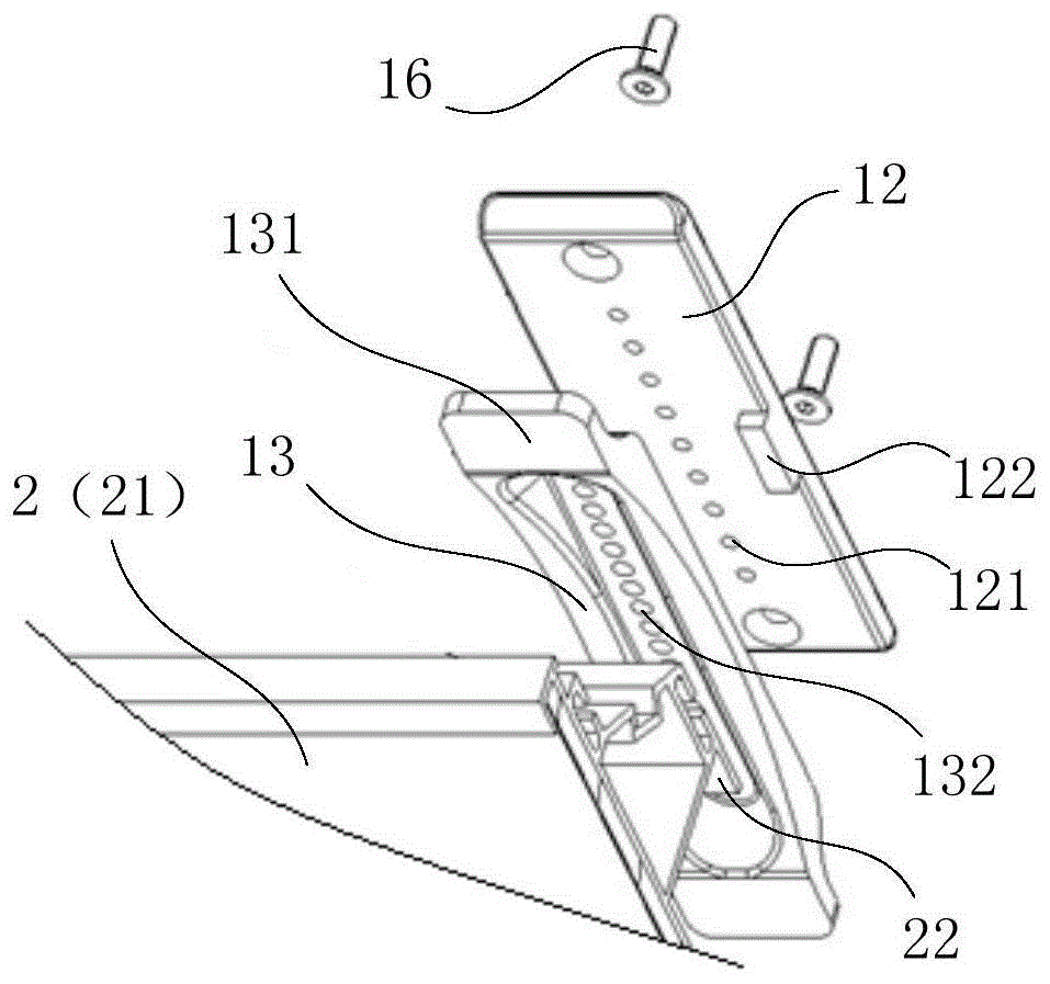
图1为本发明实施例的投影屏幕的安装调节组件的上支架的第一种实现方式与投影屏幕安装的分解结构示意图;FIG. 1 is a first implementation manner of an upper bracket of an installation adjustment assembly of a projection screen according to an embodiment of the present invention and an exploded schematic diagram of the installation of the projection screen;
图2为本发明实施例的投影屏幕的安装调节组件的上支架的第二种实现方式与投影屏幕安装的结构示意图;2 is a second implementation manner of the upper bracket of the installation and adjustment assembly of the projection screen according to the embodiment of the present invention and a schematic structural diagram of the installation of the projection screen;
图3为本发明实施例的投影屏幕的安装调节组件的下支架的第一种实现方式与投影屏幕安装的结构示意图;3 is a first implementation manner of the lower bracket of the installation adjustment assembly of the projection screen according to the embodiment of the present invention and a schematic structural diagram of the installation of the projection screen;
图4为本发明实施例的投影屏幕的安装调节组件的下支架的第二种实现方式与投影屏幕安装的结构示意图;4 is a second implementation manner of the lower bracket of the installation adjustment assembly of the projection screen according to the embodiment of the present invention and a schematic structural diagram of the installation of the projection screen;
图5为本发明实施例的投影屏幕的安装调节组件的上支架的第一种实现方式的结构示意图;5 is a schematic structural diagram of a first implementation manner of the upper bracket of the installation and adjustment assembly of the projection screen according to the embodiment of the present invention;
图6为本发明实施例的投影屏幕的安装调节组件的上支架的第二种实现方式的结构示意图;6 is a schematic structural diagram of a second implementation manner of the upper bracket of the installation and adjustment assembly of the projection screen according to the embodiment of the present invention;
图7为本发明实施例的投影屏幕的安装调节组件的上支架的第二种实现方式与投影屏幕安装的分解结构示意图;7 is a schematic diagram of a second implementation of the upper bracket of the installation and adjustment assembly of the projection screen according to the embodiment of the present invention and the exploded structural diagram of the installation of the projection screen;
图8为本发明实施例的投影屏幕的安装调节组件的上支架的第二种实现方式的第一调节齿的结构示意图一;8 is a first structural schematic diagram of a first adjustment tooth of a second implementation manner of the upper bracket of the installation adjustment assembly of the projection screen according to the embodiment of the present invention;
图9为本发明实施例的投影屏幕的安装调节组件的上支架的第二种实现方式的第一调节齿的结构示意图二;9 is a second structural schematic diagram of a first adjusting tooth of a second implementation manner of the upper bracket of the installation adjusting assembly of the projection screen according to the embodiment of the present invention;
图10为本发明实施例的投影屏幕的安装调节组件的下支架的第一种实现方式的结构示意图;10 is a schematic structural diagram of a first implementation manner of the lower bracket of the installation and adjustment assembly of the projection screen according to the embodiment of the present invention;
图11为本发明实施例的投影屏幕的安装调节组件的下支架的第二种实现方式的结构示意图;11 is a schematic structural diagram of a second implementation manner of the lower bracket of the installation and adjustment assembly of the projection screen according to the embodiment of the present invention;
图12为本发明实施例的投影屏幕的安装调节组件的下支架的第二种实现方式与投影屏幕安装的分解结构示意图;12 is a schematic diagram of a second implementation of the lower bracket of the installation and adjustment assembly of the projection screen according to the embodiment of the present invention and the exploded structural diagram of the installation of the projection screen;
图13为本发明实施例的投影屏幕的上挂钩的结构示意图。FIG. 13 is a schematic structural diagram of an upper hook of a projection screen according to an embodiment of the present invention.
附图标记:Reference number:
1-安装调节组件;11-上支架;12-固定架;121-第一调节孔;122-限位凸起;123-第一调节齿;124-定位孔;13-调节架;131-挂接部;132-第二调节孔;133-第二调节齿;134-第一长孔;14-下支架;141-第一磁性吸附件;142-第二磁性吸附件;143-限位孔;144-限位轴;145-挂钩;146-第二长孔;15-连接件;16-紧固件;17-双面胶;2-投影屏幕;21-屏幕本体;22-上挂接部;23-下挂接部。1-Installation adjustment assembly; 11-Up bracket; 12-Fixed frame; 121-First adjustment hole; 122-Limiting protrusion; 123-First adjustment tooth; 124-Location hole; 13-Adjustment frame; 132-second adjustment hole; 133-second adjustment tooth; 134-first long hole; 14-lower bracket; 141-first magnetic adsorption piece; 142-second magnetic adsorption piece; 143-limiting hole ;144-Limiting shaft; 145-Hook; 146-Second slotted hole; 15-Connector; 16-Fastener; 17-Double-sided tape; 2-Projection screen; 21-Screen body; 22-Up hook part; 23 - lower hook part.
具体实施方式Detailed ways
下面将结合本发明实施例中的附图,对本发明实施例中的技术方案进行清楚、完整地描述,显然,所描述的实施例仅仅是本发明一部分实施例,而不是全部的实施例。基于本发明中的实施例,本领域普通技术人员在没有做出创造性劳动前提下所获得的所有其他实施例,都属于本发明保护的范围。The technical solutions in the embodiments of the present invention will be clearly and completely described below with reference to the accompanying drawings in the embodiments of the present invention. Obviously, the described embodiments are only a part of the embodiments of the present invention, but not all of the embodiments. Based on the embodiments of the present invention, all other embodiments obtained by those of ordinary skill in the art without creative efforts shall fall within the protection scope of the present invention.
在本发明的描述中,需要理解的是,术语“中心”、“上”、“下”、“前”、“后”、“左”、“右”、“竖直”、“水平”、“顶”、“底”、“内”、“外”等指示的方位或位置关系为基于附图或装配所示的方位或位置关系,仅是为了便于描述本发明和简化描述,而不是指示或暗示所指的装置或元件必须具有特定的方位、以特定的方位构造和操作,因此不能理解为对本发明的限制。In the description of the present invention, it should be understood that the terms "center", "upper", "lower", "front", "rear", "left", "right", "vertical", "horizontal", The orientation or positional relationship indicated by "top", "bottom", "inner", "outer", etc. is based on the orientation or positional relationship shown in the drawings or assemblies, and is only for the convenience of describing the present invention and simplifying the description, rather than indicating Or imply that the device or element referred to must have a particular orientation, be constructed and operate in a particular orientation, and therefore should not be construed as limiting the invention.
术语“第一”、“第二”仅用于描述目的,而不能理解为指示或暗示相对重要性或者隐含指明所指示的技术特征的数量。由此,限定有“第一”、“第二”的特征可以明示或者隐含地包括一个或者更多个该特征。在本发明的描述中,除非另有说明,“多个”的含义是两个或两个以上。The terms "first" and "second" are only used for descriptive purposes, and should not be construed as indicating or implying relative importance or implicitly indicating the number of technical features indicated. Thus, a feature defined as "first" or "second" may expressly or implicitly include one or more of that feature. In the description of the present invention, unless otherwise specified, "plurality" means two or more.
在本发明的描述中,需要说明的是,除非另有明确的规定和限定,术语“安装”、“相连”、“连接”应做广义理解,例如,可以是固定连接,也可以是可拆卸连接,或一体地连接。对于本领域的普通技术人员而言,可以具体情况理解上述术语在本发明中的具体含义。In the description of the present invention, it should be noted that the terms "installed", "connected" and "connected" should be understood in a broad sense, unless otherwise expressly specified and limited, for example, it may be a fixed connection or a detachable connection connected, or integrally connected. For those of ordinary skill in the art, the specific meanings of the above terms in the present invention can be understood in specific situations.
本发明实施例的投影屏幕的安装调节组件1,用于将投影屏幕2安装于安装面上,包括:The
如图1和图2所示,上支架11,上支架11包括固定架12和调节架13,固定架12用于固定在安装面上,调节架13上设有挂接部131,挂接部131用于与投影屏幕2的上端挂接,以阻止投影屏幕2向下移动,固定架12和调节架13之间通过调节结构连接,调节结构可调节固定架12和调节架13沿竖直方向的相对位置;As shown in FIG. 1 and FIG. 2 , the upper bracket 11 includes a fixing
如图3和图4所示,下支架14,下支架14用于与投影屏幕2的下端可拆卸连接,下支架14能够限定投影屏幕2沿厚度方向的自由度。As shown in FIG. 3 and FIG. 4 , the
本发明实施例的投影屏幕的安装调节组件1,包括上支架11和下支架14,其中,如图1和图2所示,上支架11包括固定架12和调节架13,上支架11通过固定架12固定在安装面上,调节架13上设有挂接部131,投影屏幕2的上端可以挂接在挂接部131上,以阻止投影屏幕2向下移动;如图3和图4所示,下支架14与投影屏幕2下端连接,且能够限定投影屏幕2沿厚度方向的自由度。进而,通过上支架11和下支架14,可以将投影屏幕2固定在安装面上。为了可以方便对安装后的投影屏幕2位置进行调整,上支架11的固定架12和调节架13之间设有调节结构,调节结构可调节固定架12和调节架13沿竖直方向的相对位置,即,可调节投影屏幕2和安装面沿竖直方向的相对位置。同时,下支架14与投影屏幕2的下端可拆卸连接,在投影屏幕2需要调整位置时,可以很方便地将下支架14与投影屏幕2拆卸,以对投影屏幕2的位置进行调整。相比现有技术,在安装投影屏幕2时,由于上支架11的调节结构可调节固定架12和调节架13沿竖直方向的相对位置,因此,上支架11的安装位置精度要求相对较低,即使上支架11的位置有些许偏差,也可以通过调节结构调节固定架12和调节架13沿竖直方向的相对位置,来保证挂接部131可与投影屏幕2配合,进而安装投影屏幕2简单方便;当投影设备与投影屏幕2的竖直方向不吻合时,将下支架14与投影屏幕2拆卸,此时,不用将投影屏幕2取下,通过调节结构可直接调节固定架12和调节架13沿竖直方向的相对位置,即,调节投影屏幕2和安装面沿竖直方向的相对位置。The installation and
需要说明的是,当投影屏幕2安装在安装面上后,需要对投影屏幕2的空间方位进行调整,以使投影屏幕2与投影设备相对应,才能达到最好的显示效果。其中,投影屏幕2的空间方位包括水平位置、垂直位置,以及投影屏幕2的屏幕倾斜角度等。参照图1和图2,由于投影屏幕2的上端是挂接在上支架12上,投影屏幕2沿水平方向具有一定的位移空间可以进行调整;由于调节结构可调节固定架12和调节架13沿竖直方向的相对位置,进而可以通过调节结构调节投影屏幕2沿竖直方向的位置;参照图3和图4,由于下支架14能够限定投影屏幕2沿厚度方向的自由度,通过下支架14与上支架13共同作用,可以控制投影屏幕2的屏幕倾斜角度。It should be noted that, after the
调节结构的实现方式有多种,其中一种实现方式如图1和图5所示,调节结构包括沿竖直方向设置于固定架12上的多个第一调节孔121、沿竖直方向设置于调节架13上的多个第二调节孔132、以及连接件15,当任一第一调节孔121和任一第二调节孔132相对时,连接件15可穿过第一调节孔121和第二调节孔132将固定架12和调节架13连接。这样,当固定架12和调节架13沿竖直方向的相对位置变化时,只要任一第一调节孔121和任一第二调节孔132相对,连接件15就可穿过第一调节孔121和第二调节孔132将固定架12和调节架13连接。沿竖直方向设置的多个第一调节孔121和多个第二调节孔132可以实现固定架12和调节架13沿竖直方向的多个不同的相对位置。There are many ways to realize the adjustment structure, one of which is shown in FIG. 1 and FIG. 5 , the adjustment structure includes a plurality of first adjustment holes 121 arranged on the fixing
需要说明的是,连接件15可为常见的连接件,例如螺钉和销钉等;同时,连接件15的数量可以是一个,也可以是多个。其中,优选地采用两个螺钉来固定,保证固定架12和调节架13的可靠性。It should be noted that the connecting
为了提高调整的精度,以及方便第一调节孔121和第二调节孔132对位,如图5所示,相邻两个第一调节孔121之间的间距与相邻两个第二调节孔132之间的间距相等。这样,第一调节孔121和第二调节孔132的对位比较方便,且当固定架12和调节架13沿竖直方向的相对位置线性变化时,每次第一调节孔121和第二调节孔132对位,使固定架12和调节架13沿竖直方向的相对位置变化的距离是一致的,进而操作调整时可以准确把握调整幅度,提高调整的精度。In order to improve the adjustment accuracy and facilitate the alignment of the first adjustment holes 121 and the second adjustment holes 132, as shown in FIG. 5, the distance between the two adjacent first adjustment holes 121 is The spacing between 132 is equal. In this way, the alignment of the
由于第一调节孔121和第二调节孔132均是沿竖直方向设置的,如果固定架12和调节架13在水平方向上发生错位,第一调节孔121和第二调节孔132的对位就比较困难。为了避免上述问题,如图5所示,固定架12沿水平方向的两侧分别设有限位凸起122,调节架13设置于固定架12沿水平方向两侧的限位凸起122之间。这样,当调节件13沿固定架13滑动时,两个限位凸起122可以限位调节架13沿水平方向的运动,进而,沿竖直方向设置的第一调节孔121和第二调节孔132对位就比较简单。Since both the
需要说明的是,限位凸起122的数量可以根据实际需要设置,只要在固定架12沿水平方向两侧都设有限位凸起122,即可限位调节架13沿水平方向的运动,优选地,如图5所示,限位凸起122为两个,且分别位于固定架12沿水平方向两侧。It should be noted that the number of the limiting
调节结构的另外一种实现方式,如图2、图6和图7所示,调节结构包括沿竖直方向设置于固定架12上的多个第一调节齿123、沿竖直方向设置于调节架13上的多个第二调节齿133、以及连接件15,当第一调节齿123和第二调节齿133配合时,第一调节齿123和第二调节齿133之间的卡接力可阻止调节架13相对于固定架12向下移动,连接件15可将固定架12和调节架13沿厚度方向压紧连接。这样,通过多个第一调节齿123和多个第二调节齿133配合,可以使固定架12和调节架13沿竖直方向的相对位置可调节,当固定架12和调节架13沿竖直方向的相对位置到达需要的位置时,连接件15可将固定架12和调节架13沿厚度方向压紧连接,使第一调节齿123和第二调节齿133紧密配合,进而第一调节齿123和第二调节齿133之间的卡接力可阻止调节架13相对于固定架12向下移动,实现固定架12和调节架13沿竖直方向的相对位置的固定。Another implementation of the adjustment structure, as shown in FIG. 2 , FIG. 6 and FIG. 7 , the adjustment structure includes a plurality of
对于设置第一调节齿123和第二调节齿133的结构来说,连接件15可以是采用压板类的连接件15,在两侧将固定架12和调节架13压紧固定;也可以是螺钉和销钉等,通过在固定架12和调节架13上开孔,然后螺钉和销钉等穿过孔将固定架12和调节架13固定;具体地,如图6所示,固定架12上沿竖直方向间隔设有多个定位孔124,调节架13上设有沿竖直方向延伸的第一长孔134,连接件15可穿过定位孔124和第一长孔134将固定架12和调节架13压紧连接。For the structure in which the
第一调节齿123和第二调节齿133的配合,主要受力是来自于投影屏幕2的重力。由于投影屏幕2挂在调节架13上,因此,设置在调节架13上的第二调节齿133对设置在固定架12上的第一调节齿123施加竖直向下的力,即,第一调节齿123需要具有可以克服竖直向下的力的受力面,因此,如图8和图9所示,第一调节齿123包括上齿面和下齿面,上齿面为水平面或上齿面靠近齿顶的一侧向上倾斜。其中,图8所示的为第一调节齿123的上齿面为水平面的示意图;图9所示的为第一调节齿123的上齿面靠近齿顶的一侧向上倾斜的示意图。第一调节齿123的上齿面为水平面或上齿面靠近齿顶的一侧向上倾斜,即,第一调节齿123的上齿面为受力面,可以给予竖直向下的力的一个反作用力,使第一调节齿123的上齿面与第二调节齿133配合时,可以克服竖直向下的力,确保固定架12和调节架13的相对位置不发生变化。The cooperation between the first adjusting
需要说明的是,第二调节齿133的齿面形状与第一调节齿123的齿面形状是相互配合的。另外,为了防止第一调节齿123和第二调节齿133的相对位置沿水平方向移动,也可以设置限位凸台,以限位第一调节齿123和第二调节齿133沿水平方向的相对位置。另外,第一调节齿123和第二调节齿133的齿间距优选地为1毫米至10毫米,以100寸的投影屏幕2为例,第一调节齿123和第二调节齿133的齿间距采用5毫米的方案。It should be noted that the shape of the tooth surface of the second adjusting tooth 133 and the shape of the tooth surface of the
另外,参照图5和图6,固定架12与安装面的固定连接采用紧固件16来实现,紧固件16可为自攻丝或膨胀螺丝等。In addition, referring to FIGS. 5 and 6 , the fixed connection between the fixing
下支架14与投影屏幕2的下端可拆卸连接,且能够限定投影屏幕2沿厚度方向的自由度。其实现方式也有多种,其中一种实现方式如图3和图10所示,下支架14包括固定于投影屏幕2的下端的第一磁性吸附件141、以及固定于安装面上的第二磁性吸附件142,第一磁性吸附件141与第二磁性吸附件142可磁性吸合。这样,当投影屏幕2安装时,第一磁性吸附件141与第二磁性吸附件142利用磁性吸合,可限定投影屏幕2沿厚度方向的自由度,且拆卸安装比较方便。另外,利用磁性吸合来固定的结构,在安装精度上要求较低,只要第一磁性吸附件141与第二磁性吸附件142基本对位,即可实现磁性吸合,且调整位置比较容易。The
具体地,为实现第一磁性吸附件141与第二磁性吸附件142可磁性吸合,第一磁性吸附件141由磁铁制成,第二磁性吸附件142由可被磁铁吸附的材料制成;或,第二磁性吸附件142由磁铁制成,第一磁性吸附件141由可被磁铁吸附的材料制成。Specifically, in order to realize that the first
为了防止为实现第一磁性吸附件141与第二磁性吸附件142磁性吸合时发生错位,如图10所示,第一磁性吸附件141上开设有限位孔143,第二磁性吸附件142上设有限位轴144,限位轴144可配合穿设于限位孔143内。限位轴144配合穿设于限位孔143内,可给第一磁性吸附件141与第二磁性吸附件142磁性吸合时一个导向作用,防止发生错位,而在安装时辅助定位。In order to prevent misalignment when the first
第一磁性吸附件141与第二磁性吸附件142分别需要固定在投影屏幕2和安装面上,具体的固定方式有多种,但是为了方便调整和安装,至少有一侧为可拆卸连接。例如,如图10所示,第一磁性吸附件141通过双面胶17与投影屏幕2的背面粘接,第二磁性吸附件142通过紧固件16与安装面固定连接。紧固件16可为自攻丝或膨胀螺丝等。The first
下支架14的另外一种实现方式,如图4、图11和图12所示,下支架14包括固定于安装面上的挂钩145,挂钩145可与投影屏幕2的下端挂接。通过挂钩145与投影屏幕2的下端挂接,可以实现限定投影屏幕2沿厚度方向的自由度,且结构简单。Another implementation of the
但是,采用挂钩145的方式来固定,当挂钩145的位置固定后,需要对应的投影屏幕2的下端挂接部与挂钩145对位,尤其是挂钩145沿竖直方向的位置如果错位,又需要通过调节结构调整上支架11的调节架13的位置,或者重新安装挂钩145位置。因此,为了避免返工,如图11所示,挂钩145为弯板状结构,挂钩145与安装面之间通过紧固件16连接,挂钩145上开设有多个沿竖直方向延伸的第二长孔146,多个第二长孔146沿挂钩145的宽度方向排列,紧固件16穿过第二长孔146设置。挂钩145上沿竖直方向延伸的第二长孔146,可以在挂钩145安装后对挂钩145竖直方向的位置进行调整,进而避免返工。However, if the
另外,参照图12,紧固件16穿过第二长孔146,将挂钩145与安装面固定,在安装时,可以先不紧固,挂钩145可以紧固件16旋转,以方便与投影屏幕2配合。紧固件16可为自攻丝或膨胀螺丝等。In addition, referring to FIG. 12 , the
需要说明的是,本发明实施例的投影屏幕的安装调节组件1中,上述的两种调节结构的实现方式,以及上述的两种下支架14的实现方式,均为部分实施例,且两种调节结构的实现方式和两种下支架14的实现方式可任意配对。另外,本发明实施例的投影屏幕的安装调节组件1,以100寸的投影屏幕为例,对上述的两种调节结构的实现方式,以及上述的两种下支架14的实现方式做了大量的验证,可做到屏幕竖直方向上下100毫米距离的调整。It should be noted that, in the installation and
另一方面,本发明实施例还提供了一种投影屏幕,参照图1、图3以及图13,包括屏幕本体21,所述屏幕本体21的背面上端设有上挂接部22,所述上挂接部22用于与上述的安装调节组件1的调节架13上的挂接部131挂接。On the other hand, the embodiment of the present invention also provides a projection screen, referring to FIG. 1 , FIG. 3 and FIG. 13 , including a
本发明实施例的投影屏幕,屏幕本体21的背面上端设有上挂接部22,由于上挂接部22与上述的安装调节组件1的调节架13上的挂接部131挂接,通过调节结构可调节投影屏幕2和安装面沿竖直方向的相对位置,因此安装简单方便,可以调整投影屏幕2沿竖直方向的位置。In the projection screen of the embodiment of the present invention, the upper end of the back of the
参照图3,当下支架14包括固定于投影屏幕2的下端的第一磁性吸附件141、以及固定于安装面上的第二磁性吸附件142时,投影屏幕2的下端固定第一磁性吸附件141,可以不需要其他特殊结构。当然,为了使磁性吸附牢靠,投影屏幕2的下端与下支架14对应的位置,优选地为金属材料制成,例如,钢或铝等。Referring to FIG. 3 , when the
参照图4,当下支架14包括固定于安装面上的挂钩145时,屏幕本体21的背面下端设有下挂接部23,下挂接部23用于与安装调节组件1的下支架14连接。4 , when the
需要说明的是,投影屏幕2的边框可采用一体式挤塑铝型材结构,挤塑铝型材的强度高,可直接与上支架11相配合,同时保证了上支架11和下支架14与投影屏幕2隔离一段距离,降低了安装难度。It should be noted that the frame of the
以上仅为本发明的具体实施方式,但本发明的保护范围并不局限于此,任何熟悉本技术领域的技术人员在本发明揭露的技术范围内,可轻易想到的变化或替换,都应涵盖在本发明的保护范围之内。因此,本发明的保护范围应以权利要求的保护范围为准。The above are only specific embodiments of the present invention, but the protection scope of the present invention is not limited thereto. Any changes or replacements that can be easily thought of by those skilled in the art within the technical scope disclosed by the present invention should be covered. within the protection scope of the present invention. Therefore, the protection scope of the present invention should be subject to the protection scope of the claims.
Claims (14)
Priority Applications (1)
| Application Number | Priority Date | Filing Date | Title |
|---|---|---|---|
| CN201711144577.XA CN107725994B (en) | 2017-11-17 | 2017-11-17 | Installation and adjustment component of projection screen and projection screen |
Applications Claiming Priority (1)
| Application Number | Priority Date | Filing Date | Title |
|---|---|---|---|
| CN201711144577.XA CN107725994B (en) | 2017-11-17 | 2017-11-17 | Installation and adjustment component of projection screen and projection screen |
Publications (2)
| Publication Number | Publication Date |
|---|---|
| CN107725994A CN107725994A (en) | 2018-02-23 |
| CN107725994B true CN107725994B (en) | 2020-02-18 |
Family
ID=61217079
Family Applications (1)
| Application Number | Title | Priority Date | Filing Date |
|---|---|---|---|
| CN201711144577.XA Active CN107725994B (en) | 2017-11-17 | 2017-11-17 | Installation and adjustment component of projection screen and projection screen |
Country Status (1)
| Country | Link |
|---|---|
| CN (1) | CN107725994B (en) |
Families Citing this family (1)
| Publication number | Priority date | Publication date | Assignee | Title |
|---|---|---|---|---|
| CN109831633A (en) * | 2019-03-11 | 2019-05-31 | 四川长虹电器股份有限公司 | A kind of ultra-thin laser television optical screen structure |
Citations (1)
| Publication number | Priority date | Publication date | Assignee | Title |
|---|---|---|---|---|
| CN205118615U (en) * | 2015-11-24 | 2016-03-30 | 海信集团有限公司 | Wall mount arm bracket set and projection screen for projection screen |
Family Cites Families (6)
| Publication number | Priority date | Publication date | Assignee | Title |
|---|---|---|---|---|
| CN101236352A (en) * | 2008-03-03 | 2008-08-06 | 广东威创视讯科技股份有限公司 | Projection screen |
| CN201583779U (en) * | 2009-11-30 | 2010-09-15 | 广东威创视讯科技股份有限公司 | Projection screen with height-adjustable hanging |
| CN102606868B (en) * | 2012-03-14 | 2014-01-08 | 海信集团有限公司 | a wall mount |
| CN105791727A (en) * | 2014-12-26 | 2016-07-20 | 海信集团有限公司 | Soft screen support adjustment device and projection display device |
| CN106483752B (en) * | 2016-12-21 | 2019-04-09 | 海信集团有限公司 | Projection Screen Mounting Mechanism |
| CN106842797B (en) * | 2017-04-25 | 2019-04-23 | 青岛海信电器股份有限公司 | A laser projection screen |
-
2017
- 2017-11-17 CN CN201711144577.XA patent/CN107725994B/en active Active
Patent Citations (1)
| Publication number | Priority date | Publication date | Assignee | Title |
|---|---|---|---|---|
| CN205118615U (en) * | 2015-11-24 | 2016-03-30 | 海信集团有限公司 | Wall mount arm bracket set and projection screen for projection screen |
Also Published As
| Publication number | Publication date |
|---|---|
| CN107725994A (en) | 2018-02-23 |
Similar Documents
| Publication | Publication Date | Title |
|---|---|---|
| JP5158658B2 (en) | Glass plate mounting structure and mounting method for thin display | |
| US11846840B2 (en) | Display device | |
| CN209196507U (en) | a display device | |
| CN115210691A (en) | Display screen splicing structure and intelligent interactive panel | |
| CN106483752B (en) | Projection Screen Mounting Mechanism | |
| CN205118615U (en) | Wall mount arm bracket set and projection screen for projection screen | |
| CN203812506U (en) | Display panel | |
| CN214175581U (en) | Display screen splicing structure and intelligent interactive panel | |
| CN210831566U (en) | Mounting kit, panel light with mounting kit, and panel light combination | |
| US10791854B2 (en) | Bracket and display device | |
| CN209843093U (en) | Hanger structure, diaphragm and backlight module | |
| CN107725994A (en) | The installation and adjustment component and projection screen of a kind of projection screen | |
| CN109538896B (en) | Splicing adjustment module and display screen including the same | |
| WO2022095990A1 (en) | Projection screen and projection device | |
| CN209325541U (en) | A kind of ceiling installation panel light | |
| CN106483753A (en) | Projection screen installing mechanism | |
| CN109506356B (en) | Wall-hung bracket for air conditioner | |
| CN208886336U (en) | A kind of camera mounting bracket and photographic device | |
| CN208848517U (en) | Rear shell installing mechanism and display screen | |
| CN108109524B (en) | Display device and display panel thereof | |
| CN209581334U (en) | A vehicle and its bracket | |
| CN220435849U (en) | wall mount | |
| JP2007272097A (en) | Projector and projector suspension | |
| KR20090061701A (en) | Wall TV Fixture | |
| CN218149452U (en) | Formula decoration panel mounting structure is inhaled to magnetism |
Legal Events
| Date | Code | Title | Description |
|---|---|---|---|
| PB01 | Publication | ||
| PB01 | Publication | ||
| SE01 | Entry into force of request for substantive examination | ||
| SE01 | Entry into force of request for substantive examination | ||
| GR01 | Patent grant | ||
| GR01 | Patent grant |