CN107561896B - Image forming apparatus and image heating apparatus - Google Patents
Image forming apparatus and image heating apparatus Download PDFInfo
- Publication number
- CN107561896B CN107561896B CN201710500044.4A CN201710500044A CN107561896B CN 107561896 B CN107561896 B CN 107561896B CN 201710500044 A CN201710500044 A CN 201710500044A CN 107561896 B CN107561896 B CN 107561896B
- Authority
- CN
- China
- Prior art keywords
- image
- heating
- recording material
- amount
- respect
- Prior art date
- Legal status (The legal status is an assumption and is not a legal conclusion. Google has not performed a legal analysis and makes no representation as to the accuracy of the status listed.)
- Active
Links
Images


Classifications
-
- G—PHYSICS
- G03—PHOTOGRAPHY; CINEMATOGRAPHY; ANALOGOUS TECHNIQUES USING WAVES OTHER THAN OPTICAL WAVES; ELECTROGRAPHY; HOLOGRAPHY
- G03G—ELECTROGRAPHY; ELECTROPHOTOGRAPHY; MAGNETOGRAPHY
- G03G15/00—Apparatus for electrographic processes using a charge pattern
- G03G15/20—Apparatus for electrographic processes using a charge pattern for fixing, e.g. by using heat
- G03G15/2003—Apparatus for electrographic processes using a charge pattern for fixing, e.g. by using heat using heat
- G03G15/2014—Apparatus for electrographic processes using a charge pattern for fixing, e.g. by using heat using heat using contact heat
- G03G15/2039—Apparatus for electrographic processes using a charge pattern for fixing, e.g. by using heat using heat using contact heat with means for controlling the fixing temperature
- G03G15/2042—Apparatus for electrographic processes using a charge pattern for fixing, e.g. by using heat using heat using contact heat with means for controlling the fixing temperature specially for the axial heat partition
-
- G—PHYSICS
- G03—PHOTOGRAPHY; CINEMATOGRAPHY; ANALOGOUS TECHNIQUES USING WAVES OTHER THAN OPTICAL WAVES; ELECTROGRAPHY; HOLOGRAPHY
- G03G—ELECTROGRAPHY; ELECTROPHOTOGRAPHY; MAGNETOGRAPHY
- G03G13/00—Electrographic processes using a charge pattern
- G03G13/20—Fixing, e.g. by using heat
-
- G—PHYSICS
- G03—PHOTOGRAPHY; CINEMATOGRAPHY; ANALOGOUS TECHNIQUES USING WAVES OTHER THAN OPTICAL WAVES; ELECTROGRAPHY; HOLOGRAPHY
- G03G—ELECTROGRAPHY; ELECTROPHOTOGRAPHY; MAGNETOGRAPHY
- G03G15/00—Apparatus for electrographic processes using a charge pattern
- G03G15/20—Apparatus for electrographic processes using a charge pattern for fixing, e.g. by using heat
- G03G15/2003—Apparatus for electrographic processes using a charge pattern for fixing, e.g. by using heat using heat
- G03G15/2014—Apparatus for electrographic processes using a charge pattern for fixing, e.g. by using heat using heat using contact heat
- G03G15/2017—Structural details of the fixing unit in general, e.g. cooling means, heat shielding means
- G03G15/2028—Structural details of the fixing unit in general, e.g. cooling means, heat shielding means with means for handling the copy material in the fixing nip, e.g. introduction guides, stripping means
-
- G—PHYSICS
- G03—PHOTOGRAPHY; CINEMATOGRAPHY; ANALOGOUS TECHNIQUES USING WAVES OTHER THAN OPTICAL WAVES; ELECTROGRAPHY; HOLOGRAPHY
- G03G—ELECTROGRAPHY; ELECTROPHOTOGRAPHY; MAGNETOGRAPHY
- G03G15/00—Apparatus for electrographic processes using a charge pattern
- G03G15/20—Apparatus for electrographic processes using a charge pattern for fixing, e.g. by using heat
- G03G15/2003—Apparatus for electrographic processes using a charge pattern for fixing, e.g. by using heat using heat
- G03G15/2014—Apparatus for electrographic processes using a charge pattern for fixing, e.g. by using heat using heat using contact heat
- G03G15/2039—Apparatus for electrographic processes using a charge pattern for fixing, e.g. by using heat using heat using contact heat with means for controlling the fixing temperature
- G03G15/2046—Apparatus for electrographic processes using a charge pattern for fixing, e.g. by using heat using heat using contact heat with means for controlling the fixing temperature specially for the influence of heat loss, e.g. due to the contact with the copy material or other roller
-
- G—PHYSICS
- G03—PHOTOGRAPHY; CINEMATOGRAPHY; ANALOGOUS TECHNIQUES USING WAVES OTHER THAN OPTICAL WAVES; ELECTROGRAPHY; HOLOGRAPHY
- G03G—ELECTROGRAPHY; ELECTROPHOTOGRAPHY; MAGNETOGRAPHY
- G03G15/00—Apparatus for electrographic processes using a charge pattern
- G03G15/20—Apparatus for electrographic processes using a charge pattern for fixing, e.g. by using heat
- G03G15/2003—Apparatus for electrographic processes using a charge pattern for fixing, e.g. by using heat using heat
- G03G15/2014—Apparatus for electrographic processes using a charge pattern for fixing, e.g. by using heat using heat using contact heat
- G03G15/2053—Structural details of heat elements, e.g. structure of roller or belt, eddy current, induction heating
-
- G—PHYSICS
- G03—PHOTOGRAPHY; CINEMATOGRAPHY; ANALOGOUS TECHNIQUES USING WAVES OTHER THAN OPTICAL WAVES; ELECTROGRAPHY; HOLOGRAPHY
- G03G—ELECTROGRAPHY; ELECTROPHOTOGRAPHY; MAGNETOGRAPHY
- G03G21/00—Arrangements not provided for by groups G03G13/00 - G03G19/00, e.g. cleaning, elimination of residual charge
- G03G21/20—Humidity or temperature control also ozone evacuation; Internal apparatus environment control
- G03G21/206—Conducting air through the machine, e.g. for cooling, filtering, removing gases like ozone
-
- G—PHYSICS
- G03—PHOTOGRAPHY; CINEMATOGRAPHY; ANALOGOUS TECHNIQUES USING WAVES OTHER THAN OPTICAL WAVES; ELECTROGRAPHY; HOLOGRAPHY
- G03G—ELECTROGRAPHY; ELECTROPHOTOGRAPHY; MAGNETOGRAPHY
- G03G2215/00—Apparatus for electrophotographic processes
- G03G2215/20—Details of the fixing device or porcess
- G03G2215/2003—Structural features of the fixing device
- G03G2215/2016—Heating belt
- G03G2215/2035—Heating belt the fixing nip having a stationary belt support member opposing a pressure member
Abstract
An image forming apparatus and an image heating apparatus are disclosed. The present invention is characterized in that the control section sets the amount of heating with respect to the area where the image is formed and the amount of heating with respect to the area where the image is not formed, respectively, in a single recording material, and the difference between the amount of heating with respect to the area where the image is formed and the amount of heating of the area where the image is not formed differs depending on the type of the recording material.
Description
Technical Field
The present invention relates to an image forming apparatus such as a copying machine and a printer using an electrophotographic system or an electrostatic recording system. The present invention also relates to an image heating apparatus such as a fixing unit mounted to an image forming apparatus, and a gloss applying apparatus that re-heats a toner image fixed to a recording material to improve a gloss value of the toner image.
Background
A system has been proposed to meet the demand for power saving, which selectively heats an image portion formed on a recording material in an image heating apparatus such as a fixing unit and a gloss applying apparatus used in an electrophotographic image forming apparatus such as a copying machine and a printer (hereinafter referred to as an image forming apparatus) (japanese patent application laid-open No. h 6-95540). In this system, heating areas divided into a plurality are provided in a direction perpendicular to a sheet passing direction of the recording material (hereinafter referred to as a longitudinal direction), and a plurality of heat generating elements that heat the respective heating areas are provided in the longitudinal direction. Further, based on image information of an image formed in each heating area, an image portion (an area on the recording material where the image is formed) is selectively heated by the corresponding heat generating element. Further, a method of adjusting heating conditions according to image information to achieve power saving has also been proposed (japanese patent application laid-open No. 2007-271870).
Performing optimum heating control on an image in each heating area using the methods described in japanese patent application laid-open nos. h6-95540 and 2007-271870 yields a high power saving effect. However, it is found that when the amount of heating differs depending on the region in one sheet of recording material, deformation of the recording material may occur, and a decrease in stacking performance of the recording material when the recording material is discharged onto the discharge tray may be caused.
Disclosure of Invention
An object of the present invention is to provide an image heating apparatus capable of suppressing deformation of a recording material.
Another object of the present invention is to provide an image heating apparatus capable of suppressing deformation of a recording material while suppressing power consumption.
Another object of the present invention is to provide an image heating apparatus that heats an image formed on a recording material, the image heating apparatus including:
a heater having a plurality of heat generating elements arranged in a direction orthogonal to a conveying direction of a recording material; and
a control portion that controls electric power to be supplied to the plurality of heat generating elements, the control portion being capable of individually controlling the plurality of heat generating elements, wherein
The control section sets, in a single sheet of recording material, a heating amount with respect to an area where an image is formed and a heating amount with respect to an area where no image is formed, respectively, and
the difference between the amount of heating with respect to the area where an image is formed and the amount of heating with respect to the area where no image is formed differs depending on the type of recording material.
Another object of the present invention is to provide an image forming apparatus, comprising:
an image forming section that forms an image on a recording material; and
a fixing section that fixes the image formed on the recording material to the recording material, wherein
The fixing portion is an image heating device.
Another object of the present invention is to provide an image heating apparatus which heats an image formed on a recording material, the image heating apparatus comprising:
a heater having a plurality of heat generating elements arranged in a direction orthogonal to a conveying direction of a recording material; and
a control portion that controls electric power to be supplied to the plurality of heat generating elements, the control portion being capable of individually controlling the plurality of heat generating elements, wherein
The image heating apparatus is capable of setting at least a thin paper mode and a plain paper mode,
the control section sets, in a single sheet of recording material, a heating amount with respect to an area where an image is formed and a heating amount with respect to an area where no image is formed, respectively, and
the difference between the amount of heating with respect to the area where the image is formed and the amount of heating with respect to the area where the image is not formed differs between the thin paper mode and the plain paper mode.
Another object of the present invention is to provide an image forming apparatus comprising:
an image forming section that forms an image on a recording material; and
a fixing section that fixes the image formed on the recording material to the recording material, wherein
The fixing portion is an image heating device.
Other features of the present invention will become apparent from the following description of exemplary embodiments with reference to the attached drawings.
Drawings
Fig. 1 is a schematic cross-sectional view of an image forming apparatus 100 according to an example of the present invention;
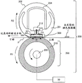
fig. 2 is a schematic sectional view of a fixing device 200 according to example 1;
fig. 3A to 3C are schematic configuration diagrams of a heater 300 according to example 1;
fig. 4 is a schematic diagram of a heater control circuit 400 according to example 1.
FIG. 5 is a view showing a heating region A according to example 11To A7The figure (a).
Fig. 6 is a diagram showing an image P1 and an image heating portion PR according to example 1.
Fig. 7 shows the evaluation results of the deformation of the recording material and the measurement results of the average power consumption according to example 1;
fig. 8 is a heater control flowchart according to example 2;
fig. 9 is a table of a heating mode and a temperature correction amount according to example 2;
fig. 10A and 10B are tables of temperature correction amounts according to example 3; and
fig. 11 is a diagram showing an image P2, an image P3, and their respective image heating sections according to example 4.
Detailed Description
Hereinafter, a description will be given of embodiments (examples) of the present invention with reference to the accompanying drawings. However, the size, material, shape, relative arrangement of the components, and the like described in the embodiments may be appropriately changed according to the configuration, various conditions, and the like of the apparatus to which the present invention is applied. Therefore, the size, material, shape, relative arrangement of the components, and the like described in the embodiments are not intended to limit the scope of the present invention to the following embodiments.
[ example 1]
1. Arrangement of image forming apparatus
Fig. 1 is a configuration diagram of an image forming apparatus employing an electrophotographic system according to an embodiment of the present invention. Examples of image forming apparatuses to which the present invention is applicable include copiers, printers, and the like using an electrophotographic system or an electrostatic recording system, and a case where the present invention is applied to a laser printer will be described below.
The image forming apparatus 100 includes a video controller 120 and a control section 113. As an acquisition unit that acquires information on the type or the like of the recording material and information on an image formed on the recording material, the video controller 120 receives and processes image information and a print instruction transmitted from an external apparatus such as a personal computer. The control section 113 is connected to the video controller 120, and controls the respective units constituting the image forming apparatus 100 according to instructions from the video controller 120. When the video controller 120 receives a print instruction from an external apparatus, image formation is performed by the following operations.
The image forming apparatus 100 feeds the recording material P with a feed roller 102 and conveys the recording material P toward an intermediate transfer member 103. The photosensitive drum 104 is rotationally driven counterclockwise at a prescribed speed by electric power of a driving motor (not shown), and is uniformly charged by a primary charger 105 during the rotation process. A laser beam modulated corresponding to an image signal is output from the laser beam scanner 106, and selective scanning exposure is performed on the photosensitive drum 104 to form an electrostatic latent image. Reference numeral 107 denotes a developing device that causes powder toner as a developer to adhere to the electrostatic latent image to make the electrostatic latent image visible as a toner image (developer image). The toner image formed on the photosensitive drum 104 is primarily transferred onto the intermediate transfer member 103 that rotates while being in contact with the photosensitive drum 104.
In this case, each of the photosensitive drum 104, the primary charger 105, the laser beam scanner 106, and the developing device 107 is arranged for each of four colors of cyan (C), magenta (M), yellow (Y), and black (B). The toner images corresponding to the four colors are sequentially transferred onto the intermediate transfer member 103 through the same process so as to overlap each other. The toner image transferred onto the intermediate transfer member 103 is secondarily transferred onto the recording material P at a secondary transfer unit formed by the intermediate transfer member 103 and a transfer roller 108 by a transfer bias applied to the transfer roller 108. The arrangement related to the formation of the unfixed image on the recording material P corresponds to the image forming portion. Subsequently, when the fixing device 200 as an image heating device applies heat and pressure to the recording material P, the toner image is fixed, and the recording material P is discharged to the outside as an article of image formation.
The control section 113 manages the conveyance state of the recording material P using a conveyance sensor 114, a resist sensor 115, a pre-fixing sensor 116, and a fixing discharge sensor 117 arranged on the conveyance path of the recording material P. Further, the control portion 113 includes a storage unit that stores a temperature control program and a temperature control table of the fixing device 200. A control circuit 400 as a heater driving device connected to a commercial AC power source 401 supplies power to the fixing device 200.
Further, this example uses an image forming apparatus in which the maximum sheet passing width in the direction perpendicular to the conveying direction of the recording material P is 216mm, and 40 sheets of plain paper of the LETTER size (216mm × 279mm) can be printed per minute at a conveying speed of 220 mm/sec.
Further, with the image forming apparatus according to the present example, information on the print mode for transferring the recording material P is transmitted as one of print instructions from an external device such as a host computer. Alternatively, the print mode may be appropriately selected on the operation panel of the image forming apparatus.
The print mode refers to a mode that a user can set to achieve an optimum print output according to the type of the recording material P. In the following description, a printing mode related to image heating will be referred to as a heating mode. In the present example, the following plural heating modes are set as the heating modes according to the thickness information of the recording material P. Specifically, the heating mode includes: recommended for basis weight not exceeding 70g/m2The "thin paper pattern" of the recording material of (1); recommended for basis weights greater than 70g/m2And not more than 120g/m2The "plain paper mode" of the recording material of (1); recommended for basis weights greater than 120g/m2The "heavy paper mode" of the recording material of (1). In the "heavy paper mode", by reducing the conveying speed of the recording material P by half, the toner image on the recording material P can be fixed without excessively raising the temperature of the fixing device 200.
2. Arrangement of fixing device (fixing part)
Fig. 2 is a schematic sectional view of a fixing device 200 according to the present example. The fixing device 200 includes a fixing film 202, a heater 300 contacting an inner surface of the fixing film 202, and a pressure roller 208 forming a fixing nip unit N together with the heater 300 via the fixing film 202.
The fixing film 202 is a flexible heat-resistant multilayer tubular film formed in a cylindrical shape, and a heat-resistant resin such as polyimide having a thickness of about 50 to 100 μm or a metal such as stainless steel having a thickness of about 20 to 50 μm may be used as the base layer. Further, a release layer (releasing layer) for preventing toner adhesion and ensuring separability from the recording material P is formed on the surface of the fixing film 202. The release layer is a heat-resistant resin having excellent releasability such as tetrafluoroethylene-perfluoro (alkyl vinyl ether) copolymer (PFA) having a thickness of about 10 to 50 μm. Further, in the case where the fixing film is used in an apparatus for forming a color image, in order to improve image quality, a heat-resistant rubber such as silicone rubber having a thickness of about 100 to 400 μm and a thermal conductivity of about 0.2 to 3.0W/m · K may be provided as an elastic layer between the base layer and the release layer. In this example, from the viewpoints of thermal responsiveness, image quality, durability, and the like, polyimide having a thickness of 60 μm was used as the base layer, silicone rubber having a thickness of 300 μm and a thermal conductivity of 1.6W/m · K was used as the elastic layer, and PFA having a thickness of 30 μm was used as the release layer.
The pressure roller 208 includes a core metal 209 made of a material such as iron or aluminum and an elastic layer 210 made of a material such as silicone rubber. The heater 300 is held by a heater holding member 201 made of heat-resistant resin, and heats the fixing film 202. The heater holding member 201 also has a guide function for guiding the rotation of the fixing film 202. The metal bracket 204 receives a pressing force (not shown) from a biasing member or the like, and biases the heater holding member 201 toward the pressing roller 208. The pressure roller 208 rotates in the direction of arrow R1 due to the power received from the motor 30. The rotation of the pressure roller 208 is followed by the rotation of the fixing film 202 in the direction of the arrow R2. While the recording material P is nipped and conveyed at the fixing nip unit N, the unfixed toner image on the recording material P is fixed by applying heat of the fixing film 202.
The heater 300 is a heater in which a heat generating resistor as a heat generating element provided on a ceramic substrate 305 generates heat when energized. The heater 300 includes a surface protection layer 308 that is in contact with the inner surface of the fixing film 202, and a surface protection layer 307 that is provided on a side (hereinafter referred to as a back surface side) opposite to a side (hereinafter referred to as a sliding surface side) of the substrate 305 on which the surface protection layer 308 is provided. A power supply electrode (electrode E4 is shown as a representative) is provided on the back surface side of the heater 300. Reference character C4 denotes an electrical contact point that is in contact with the electrode E4, so that electric power is supplied from the electrical contact point to the electrode. Details of the heater 300 will be provided later. Further, the safety element 212 is arranged to be opposed to the back surface side of the heater 300, wherein the safety element 212 is a thermoelectric switch, a temperature fuse, or the like, and is actuated by abnormal heat generation of the heater 300 to interrupt the power supplied to the heater 300.
3. Arrangement of heaters
Fig. 3A to 3C are schematic diagrams showing the configuration of a heater 300 according to example 1 of the present invention.
Fig. 3A is a sectional view of the heater in the vicinity of the conveyance reference position X shown in fig. 3B. The conveyance reference position X is defined as a reference position when the recording material P is conveyed. In the image forming apparatus according to the present example, the recording material P is conveyed so that a central portion of the recording material P in a width direction perpendicular to a conveying direction of the recording material P passes through the conveyance reference position X. The heater 300 generally has a five-layer structure in which two layers (back surface layers 1 and 2) are formed on one surface (back surface) of the substrate 305 and two layers (sliding surface layers 1 and 2) are also formed on the other surface (sliding surface) of the substrate 305.
The heater 300 has a first conductor 301(301a and 301b) disposed in the longitudinal direction of the heater 300 on the surface on the back surface layer side of the substrate 305. Further, the heater 300 has a second conductor 303 (303-4 in the vicinity of the conveyance reference position X), the second conductor 303 being disposed at a position in the longitudinal direction of the heater 300 that is different from the position of the first conductor 301 on the substrate 305 in the lateral direction of the heater (the direction perpendicular to the longitudinal direction). The first conductor 301 is separated into a conductor 301a arranged on the upstream side in the conveying direction of the recording material P and a conductor 301b arranged on the downstream side in the conveying direction of the recording material P. In addition, the heater 300 has a heat generating resistor 302, the heat generating resistor 302 being disposed between the first conductor 301 and the second conductor 303, and generating heat due to the electric power supplied via the first conductor 301 and the second conductor 303.
In the present example, the heat generating resistors 302 are separated into heat generating resistors 302a (302 a-4 near the conveyance reference position X) arranged on the upstream side in the conveyance direction of the recording material P and heat generating resistors 302b (302 b-4 near the conveyance reference position X) arranged on the downstream side in the conveyance direction of the recording material P. Further, an insulating (glass in this example) surface protection layer 307 covering the heat generating resistor 302, the first conductor 301, and the second conductor 303 are provided on the back surface layer 2 of the heater 300 to avoid the electrode unit (E4 in the vicinity of the reference position X).
Fig. 3B shows a plan view of the layers of the heater 300. On the back surface layer 1 of the heater 300, a plurality of heat generating blocks made of a set of a first conductor 301, a second conductor 303, and a heat generating resistor 302 are disposed in the longitudinal direction of the heater 300. The heater 300 according to the present example has seven heat generation blocks HB1 to HB7 in total in the longitudinal direction of the heater 300. The heating region ranged from the left end of the heat generating block HB1 in the figure to the right end of the heat generating block HB7 in the figure, and the length of the heating region was 220 mm. In the present example, the width of each heat generation block in the longitudinal direction is the same (however, the width in the longitudinal direction is not necessarily the same).
The heat generation blocks HB1 through HB7 are respectively constituted by heat generation resistors 302a-1 through 302a-7 and heat generation resistors 302b-1 through 302b-7 formed symmetrically in the lateral direction of the heater 300. The first conductor 301 is constituted by a conductor 301a connected to the heat generating resistors (302a-1 to 302a-7) and a conductor 301b connected to the heat generating resistors (302b-1 to 302 b-7). In a similar manner, the second conductor 303 is divided into seven conductors 303-1 to 303-7 to correspond to seven heat generation blocks HB1 to HB 7. The heating amount of each of the seven heat generating blocks HB1 to HB7 is individually controlled by individually controlling the power of the heat generating resistors in each block.
Electrodes E1 to E7, E8-1 and E8-2 are connected to electrical contacts C1 to C7, C8-1 and C8-2. The electrodes E1 to E7 are electrodes for supplying electric power to the heat generating blocks HB1 to HB7 via conductors 303-1 to 303-7, respectively. The electrodes E8-1 and E8-2 are common electrodes for supplying electric power to the seven heat generating blocks HB1 to HB7 via the conductor 301a and the conductor 301 b. Although the electrodes E8-1 and E8-2 are provided at both ends in the longitudinal direction in the present example, a configuration may be adopted in which only the electrode E8-1 is provided on one side (in other words, a configuration in which the electrode E8-2 is not provided), or a configuration in which each of the electrodes E8-1, E8-2 is divided into two parts in the conveying direction of the recording material, for example.
The surface protective layer 307 of the back surface layer 2 of the heater 300 is formed to expose the electrodes E1 to E7, E8-1, and E8-2. Thus, a configuration of the heater 300 is achieved in which the electrical contacts C1 to C7, C8-1, and C8-2 can be connected to the respective electrodes from the back surface layer side of the heater 300, and power can be supplied from the back surface layer side. Further, a configuration is achieved in which the power supplied to at least one of the heat generation blocks and the power supplied to another heat generation block can be independently controlled.
Thermistors T1-1 to T1-4 and thermistors T2-5 to T2-7 are provided on the sliding surface layer 1 on the side of the sliding surface (surface on the side in contact with the fixing film) of the heater 300 to detect the temperature of each of the heat generation blocks HB1 to HB7 in the heater 300. The thermistors T1-1 to T1-4 and the thermistors T2-5 to T2-7 are made of a material which has a PTC property or an NTC property (NTC property in this example) and is thinly formed on a substrate. Since the thermistors are provided for all the heat generating blocks HB1 to HB7, the temperatures of all the heat generating blocks can be detected by detecting the resistance values of the thermistors.
To energize the four thermistors T1-1 to T1-4, conductors ET1-1 to ET1-4 for detecting the resistance values of the thermistors and a common conductor EG1 of the thermistors are formed. In a similar manner, in order to energize the three thermistors T2-5 to T2-7, conductors ET2-5 to ET2-7 for detecting the resistance values of the thermistors and a common conductor EG2 of the thermistors are formed.
A slidable surface protection layer 308 (glass in this example) is provided on the sliding surface layer 2 on the side of the sliding surface (surface in contact with the fixing film) of the heater 300. The surface protective layer 308 is formed to avoid both ends of the heater 300 to allow electrical contacts to be connected to conductors ET1-1 to ET1-4 and ET2-5 to ET2-7 for detecting the resistance value of the thermistor and to common conductors EG1 and EG2 of the thermistor. The surface protective layer 308 is provided at least in a region sliding against the film 202 (excluding both ends of the surface of the heater 300 opposite to the film 202).
As shown in fig. 3C, the surface opposite to the heater 300 of the heater holding member 201 is provided with holes for connecting the electrodes E1, E2, E3, E4, E5, E6, E7, E8-1, and E8-2 with the electrical contacts C1 to C7, C8-1, and C8-2. The previously described safety element 212 and electrical contacts C1-C7, C8-1 and C8-2 are disposed between the bracket 204 and the heater retaining member 201. The electrical contacts C1 to C7, C8-1 and C8-2, which are in contact with the electrodes E1 to E7, E8-1 and E8-2, respectively, are electrically connected to the electrode portions of the heater by a method such as biasing with a spring or welding. Each of the electrical contacts is connected to a control circuit 400 (described later) of the heater 300 via a cable or a conductive material such as a thin metal plate provided between the holder 204 and the heater holding member 201. In addition, the electrical contacts provided on the conductors ET1-1 to ET1-4 and ET2-5 to ET2-7 for detecting the resistance value of the thermistor and the common conductors EG1 and EG2 of the thermistor are also connected to the control circuit 400 described later.
4. Arrangement of heater control circuit
Fig. 4 is a circuit diagram of a control circuit 400 of the heater 300 according to example 1. Reference numeral 401 denotes a commercial AC power supply connected to the image forming apparatus 100. The power control of the heater 300 is performed by energizing/interrupting the energization of the triacs 411 to 417. The triacs 411 to 417 operate according to signals FUSER1 to FUSER7 from the CPU 420, respectively. The drive circuits for the triacs 411 to 417 are shown in abbreviated form. The control circuit 400 of the heater 300 has a circuit configuration that enables the seven heat generation blocks HB1 to HB7 to be independently controlled by the seven triacs 411 to 417. The zero-crossing detector 421 is a circuit that detects zero crossing of the AC power source 401, and outputs a ZEROX signal to the CPU 420. The ZEROX signal is used to detect the timing of phase control and wave number control of the triacs 411 to 417 and the like.
A method of detecting the temperature of the heater 300 will now be described. The divided voltages of the thermistors T1-1 to T1-4 and the resistors 451 to 454 are detected by the CPU 420 as signals Th1-1 to Th1-4 for the temperatures detected by the thermistors T1-1 to T1-4. In a similar manner, for the temperatures detected by the thermistors T2-5 through T2-7, the divided voltages of the thermistors T2-5 through T2-7 and the resistors 465 through 467 are detected by the CPU 420 as signals Th2-5 through Th 2-7. In the internal processing of the CPU 420, the electric power to be supplied is calculated by, for example, PI control based on the set temperature (control target temperature) of each heat generation block and the detected temperature of the thermistor. Further, the control level corresponding to the phase angle (phase control) or wave number (wave number control) of the supplied power is converted, and the triacs 411 to 417 are controlled based on the control conditions thereof.
When the temperature of the heater 300 excessively rises due to a failure or the like, the relay 430 and the relay 440 are used as a means for interrupting the power of the heater 300. The circuit operation of the relay 430 and the relay 440 will now be described. When the RLON signal assumes a High level (High) state, the transistor 433 is switched to a conductive (ON) state, the secondary side coil of the relay 430 is energized by the power supply voltage Vcc, and the primary side contact of the relay 430 is switched to a conductive state. When the RLON signal assumes a Low level (Low) state, the transistor 433 is switched to an OFF state, the current flowing from the power supply voltage Vcc to the secondary side coil of the relay 430 is interrupted, and the primary side contact of the relay 430 is switched to the OFF state. In a similar manner, when the RLON signal assumes a high level state, the transistor 443 is switched to a conducting state, the secondary side coil of the relay 440 is energized by the power supply voltage Vcc, and the primary side contact of the relay 440 is switched to a conducting state. When the RLON signal assumes a low level state, the transistor 443 is switched to an off state, the current flowing from the power supply voltage Vcc to the secondary side coil of the relay 440 is interrupted, and the primary side contact of the relay 440 is switched to the off state. Further, the resistor 434 and the resistor 444 are current limiting resistors.
The operation of the safety circuit using the relay 430 and the relay 440 will now be described. When any one of the detected temperatures of the thermistors T1-1 to T1-4 exceeds a respectively set prescribed value, the comparing unit 431 operates the latch unit 432, and the latch unit 432 latches the RLOFF1 signal in a low state. When the RLOFF1 signal assumes a low state, the relay 430 can be maintained in an off state (safe state) because the transistor 433 is maintained in an off state even when the CPU 420 changes the RLON signal to a high state. Further, in the non-latch state, the latch unit 432 sets the RLOFF1 signal to the on state output. In a similar manner, when any one of the detected temperatures of the thermistors T2-5 to T2-7 exceeds a respectively set prescribed value, the comparing unit 441 operates the latch unit 442, and the latch unit 442 latches the RLOFF2 signal in a low level state. When the RLOFF2 signal assumes a low state, the relay 440 can be maintained in an off state (safe state) because the transistor 443 is maintained in the off state even when the CPU 420 changes the RLON signal to a high state. In a similar manner, in the non-latching state, the latch unit 442 sets the RLOFF2 signal to the on state output.
5. Heater control method based on image information
In the image forming apparatus according to the present example, power supply to the seven heat generation blocks HB1 to HB7 of the heater 300 is controlled in accordance with image data (image information) sent from an external device (not shown) such as a host computer and a heating mode selected at the time of printing with the recording material P.
FIG. 5 is a view showing 7 heating areas A divided in the longitudinal direction according to the present example compared with the size of a LETTER-sized sheet1To A7The figure (a). Heating zone A1To A7Corresponding to the heat generating blocks HB1 to HB7, and configured such that the heating region A is heated1Is heated by a heat generation block HB1 and heats region A7Heated by heat generating block HB 7. In other words, the heating area A1To A7Indicating the regions that can be heated by the thermal generation blocks HB1 to HB 7. In the present example, heating zone A1To A7Has a total length (length in the sheet width direction) of 220mm, and the heating area A1To A7Each of which is its equal 7-way division (L ═ 31.4 mm). The heat generation blocks HB1 to HB7 gradually move the heating range from the downstream-side end toward the upstream-side end (from the top to the bottom in fig. 5) in the conveyance direction with respect to the recording material P being conveyed.
Fig. 6 is a diagram showing an image P1 formed on the recording material P and an image heating portion PR corresponding to the image P1 in the present example. The image heating part PR is at the heating area A1To A7Of the recording material P overlaps with an area where an image exists on the recording material P. In fig. 6, a portion PR overlapping with an image P13、PR4And PR5(shaded portion)) Corresponding to the image heating portion. In addition, except for the heating zone A1To A7Is regarded as the non-image heating portion PP. In the heating area A3To A5Middle, image heating part PR3To PR5The other portions are non-image heating portions PP. Due to the fact that the heating area A is arranged1、A2、A6And A7Is not formed in the entire area in the conveying direction, and thus the entire area thereof is the non-image heating portion PP.
The flow of heater control in this example will now be described. First, upon receiving image information from the host computer, the video controller 120 calculates the range of the image heating section PR. When the area of the recording material P corresponding to the image heating section PR passes through the fixing nip unit N, the control section 113 controls the temperature of each heat generation patch so that the unfixed toner image is fixed onto the recording material P. The image heating temperature (temperature of the heat generating element when heating the image area) Ta set at this time is set according to the heating mode. The image heating temperature Ta is a control target temperature of a heat generating element (heat generating block) that heats a region where an image is formed. In the present example, the image heating temperature Ta is set to 160 ℃ in the thin paper mode, 180 ℃ in the normal paper mode, and 180 ℃ in the heavy paper mode. Further, in the heavy paper mode, by reducing the conveying speed to half of the conveying speed in the plain paper mode, the toner image can be fixed even when the image heating temperature Ta is set lower than in the plain paper mode.
When the area of the recording material P corresponding to the non-image heating portion PP passes through the fixing nip unit N, the CPU 420 controls the temperature of each heat generation block so that the temperature of the recording material P corresponding to the non-image heating portion PP is lower than the temperature of the recording material P corresponding to the image heating portion PR. The non-image heating temperature Tp (the temperature of the heat generating element when heating the non-image area) set at this time is set according to the heating mode. The non-image heating temperature Tp is a control target temperature of the heat generating elements (heat generating blocks) that heat the region where no image is formed. In the present example, the non-image heating temperature Tp is set to 140 ℃ which is 20 ℃ lower than the image heating temperature Ta in the thin paper mode, to 140 ℃ which is 40 ℃ lower than the image heating temperature Ta in the normal paper mode, and to 120 ℃ which is 60 ℃ lower than the image heating temperature Ta in the heavy paper mode. In other words, in the present example, the temperature difference Δ T between the image heating temperature Ta and the non-image heating temperature Tp is set to Δ T of 20 ℃ in the thin paper mode, 40 ℃ in the plain paper mode, and 60 ℃ in the heavy paper mode. In short, the temperature difference is set smaller in the thin paper mode and larger in the heavy paper mode, relative to the normal paper mode.
As described above, the CPU (control section) sets the amount of heating with respect to the area in which the image is formed and the amount of heating with respect to the area in which the image is not formed, respectively, in one sheet of recording material. Further, the difference between the amount of heating with respect to the area in which the image is formed and the amount of heating with respect to the area in which the image is not formed differs depending on the type of the recording material. Specifically, the control section sets the heating amount with respect to the region in which the image is formed and the heating amount with respect to the region in which the image is not formed such that the smaller the basis weight of the recording material, the smaller the heating amount difference. Further, the heating amount difference is generated by a control section that provides a difference between a control target temperature of the heat generating element that heats the area where the image is formed and a control target temperature of the heat generating element that heats the area where the image is not formed.
In the present example, the video controller 120 as the acquisition unit acquires the thickness (in other words, basis weight) of the recording material P conveyed to the fixing device 200 as an index value indicating deformability of the recording material due to the influence of heat. When the acquired basis weight is smaller than the reference basis weight of the same-sized recording material, or in other words, when the acquired basis weight is the first basis weight at which the recording material is more deformable relative to the reference basis weight due to the influence of heat, the temperature difference Δ is set to be the first temperature difference smaller than the reference temperature difference. Further, when the acquired basis weight is larger than the reference basis weight, or in other words, when the acquired basis weight is larger than the reference basis weightWhen the basis weight is a second basis weight at which the recording material is less deformed relative to the reference basis weight due to the influence of heat, the temperature difference Δ is set to a second temperature difference larger than the reference temperature difference. In this example, the reference basis weight as the reference index value was set to 90g/m2The first basis weight as the first index value is set to 60g/m2The second basis weight as the second index value was set to 160g/m2. Further, as a prescribed temperature difference Δ between the control temperature of the image heating section and the control temperature of the non-image heating section, the reference temperature difference is set to 40 ℃, the first temperature difference is set to 20 ℃, and the second temperature difference is set to 60 ℃. Further, the specific numerical value setting is appropriately different depending on the type of recording material, the apparatus specification, and the like. Further, the detected temperature for temperature control is not limited to the detected temperature of the heater by the thermistor as in the configuration of the present example, and the temperature of any position other than the heater in the fixing device 200 may be detected for temperature control.
Further, although the present embodiment employs a configuration in which the control temperatures of the image heating section and the non-image heating section are controlled so as to keep the heating amount difference between the heating amount of the image heating section and the heating amount of the non-image heating section within the prescribed heating amount difference, such a configuration is not limitative. For example, a difference in power (calculation of power consumption of electricity) of the heat generating elements for the heaters may be set between the heat generating elements for heating the image heating portion and the heat generating elements for heating the non-image heating portion, and energization of each heat generating element may be individually controlled so that the power difference is kept within a prescribed power difference. By so doing, a configuration may be adopted in which the power ratio between the heat-generating elements for heating the image heating portion and the heat-generating elements for heating the non-image heating portion is controlled. In this case, as the reference heating amount difference, the reference power difference or the reference energization ratio may be appropriately set in a similar manner to the above-described reference temperature difference. In addition, as the first heating amount difference and the second heating amount difference, the first power difference or the first energization ratio and the second power difference or the second energization ratio may be appropriately set in a similar manner to the above-described first temperature difference and the second temperature difference.
Fig. 7 is a graph showing the evaluation results of the deformation of each of a plurality of recording materials having the same size and different basis weights, and the measurement results of the average power consumption when the image P1 is printed on the recording material at various recommended heating modes. Fig. 7 shows recording materials P for recording materials that are let sizes having different basis weightsA(basis weight 60 g/m)2) And a recording material PB(basis weight 90g/m2) And a recording material PC(basis weight 160g/m2) The result of (1). In addition, fig. 7 also shows an example in which the temperature difference Δ T between the image heating temperature and the non-image heating temperature as a comparative example of the present example is fixed to Δ T-40 ℃ regardless of the heating mode.
In evaluating the deformation of the recording material, after printing, when placed on a flat plate, the maximum value of the amount of swelling (uplift) of the recording material is evaluated, wherein the amount of swelling of not more than 20mm is "a (acceptable)" and the amount of swelling of more than 20mm is "U (unacceptable)". Further, as the average power consumption, the average power consumption per sheet when 10 sheets of each recording material are printed is calculated.
According to fig. 7, for the deformation of the recording material, in the comparative example where Δ T ═ 40 ℃, at a basis weight of 60g/m2Recording material P ofAThe top print produced a "U" result, while the "a" result was produced in this example where Δ T ═ 20 ℃. Furthermore, the basis weight was 90g/m2Recording material P ofBPrinted on and having a basis weight of 160g/m2Recording material P ofCThe top print produces an "a" result.
The temperature difference Δ T between the image heating temperature Ta and the non-image heating temperature Tp in the present embodiment is set to a value that keeps the deformation of the recording material P within the allowable range. In one sheet of recording material, the portion having a large amount of heating loses more moisture and shrinks more than the portion having a small amount of heating. Therefore, when the amount of heat in one page of the recording material P varies, uneven stress is generated in the page of the recording material P. The deformation state of the recording material P is determined by the balance between the hardness or rigidity of the recording material P and the uneven stress. In general, a recording material having a small basis weight has a low hardness and is therefore easily deformed. Therefore, when a recording material having a small basis weight is used, only a small temperature difference can be set in order to keep the deformation of the recording material P within an allowable range. On the other hand, a recording material having a large basis weight generally has a high hardness and is therefore not easily deformed. As a result, a large temperature difference can be set.
In addition, according to fig. 7, in the comparative example, the difference in average power consumption due to the heating mode increases. In particular, the basis weight of the resin is 160g/m2Recording material P ofCAverage power consumption per sheet 1050J when printing, in this example, when using a basis weight of 160g/m2Recording material P ofCThe power consumption can be significantly reduced to an average power consumption of 850J per sheet.
This is because the larger the basis weight of the recording material P, the larger the amount of heat applied from the fixing device 200 to the recording material P (the larger the basis weight, the larger the electric power required to raise the temperature of the recording material by 1 ℃). In this example, the recording material P is used as a heavy paperCThe temperature difference at the time of printing is set to Δ T60 ℃ (which is 20 ℃ wider than in the comparative example), so significant reduction in power consumption can be achieved while maintaining deformation of the recording material within an allowable range.
Although an example in which the rigidity of the recording material P is determined based on the basis weight as the thickness information on the recording material P to determine the heating pattern is described in the present example, the method of determining the heating pattern is not limited thereto. For example, the thickness or rigidity of the recording material P may be determined by selecting or inputting information about the type of the recording material (product name of the recording material, product type of the recording material including information such as material, size, thickness, basis weight, and the like) to determine the heating mode. Since the hardness and the optimum image heating temperature differ depending on the type of the recording material, an effect similar to that of the present example can be achieved by setting the temperature difference between the image heating temperature and the non-image heating temperature according to the type of the recording material.
As described in the present example, by setting the temperature difference Δ T between the image heating temperature Ta and the non-image heating temperature Tp according to the heating pattern at the time of printing with the recording material P, it is possible to achieve reduction in power consumption while keeping deformation of the recording material P within the allowable range.
Further, although an example in which the image formed on the recording material P is concentrated at one position has been described in the present example, the image may be dispersed (scatter) at a plurality of positions on the recording material P. In addition, each of the images dispersed at the plurality of positions may have a different image heating temperature. In this case, by setting the maximum value of the temperature difference between the image heating temperature and the non-image heating temperature on the recording material P, effects similar to the present example can be achieved.
[ example 2]
In example 2 of the present invention, the following example will be described: wherein the temperature difference between the image heating temperature and the non-image heating temperature is set after the stiffness of the recording material P is determined by detecting a characteristic such as thickness (basis weight) of the recording material P using the means for detecting the characteristic of the recording material P. Since the configuration is similar to that of embodiment 1, detailed description thereof will be omitted. It should be understood that matters not particularly described in example 2 are similar to those described in embodiment 1.
In the present example, a media sensor 118 that detects the thickness (basis weight) of the recording material is used as the recording material thickness detection means. For example, the media sensor 118 is disposed on the conveyance path of the recording material P between the resist sensor 115 and the transfer roller 108 shown in fig. 1. The media sensor 118 is a sensor that detects the thickness or basis weight of the recording material P by a method of emitting light toward the recording material P being conveyed using an LED or the like and receiving light transmitted or reflected by the recording material P, a method of transmitting and receiving ultrasonic waves, or the like.
Fig. 8 shows a flow chart according to the present example. In addition, fig. 9 shows a combination of the heating mode and the temperature correction amount according to the detection result of the medium sensor. In fig. 8, first, feeding of the recording material P is started (S802), and when the recording material P reaches the media sensor unit, the thickness (basis weight) of the recording material P is detected by the media sensor (S803). According to the detection result, the video controller 120 determines a heating mode with respect to the recording material P (S804), and determines a correction amount dT1 of the image heating temperature Ta and a correction amount dT1 of the temperature difference Δ T from the non-image heating temperature in the determined heating mode according to fig. 9 (S805). The control section 113 controls heating of the recording material P using the corrected image heating temperature Ta '═ Ta + dTa1 and the corrected temperature difference Δ T' ═ Δ T + dT1 (S806).
Since the smaller the value of the detection result of the thickness (basis weight) of the recording material P by the media sensor, the lower the hardness of the recording material P, the temperature correction amount in fig. 9 is set to reduce the temperature difference Δ T between the image heating temperature Ta and the non-image heating temperature to prevent deformation. Further, since the larger the value of the detection result, the higher the hardness of the recording material P, the temperature correction amount is set to increase the temperature difference Δ T to produce the power saving effect. Since the rigidity of the recording material P can be determined in more detail by setting the temperature correction amount as described above, it is possible to generate a power saving effect more suitable for recording materials P of various basis weights while keeping the deformation of the recording material P within an allowable range.
Although an example is included in which the temperature correction is performed with the fixed value of the temperature correction amount shown in fig. 9 depending on which basis weight range the basis weight detected by the media sensor is within, the control method is not limited to this. For example, the temperature correction may be performed by linearly interpolating the temperature correction amount shown in fig. 9 according to the basis weight detected by the media sensor. Further, although the heating mode and the temperature correction amount are determined based only on the detection result of the medium sensor with respect to the recording material P, the correction method is not limited thereto. For example, when the type of the recording material P is known in advance, a method may be used in which the temperature difference Δ T is corrected by comparing the basic characteristic information of the recording material P as a reference and the detection result obtained by the media sensor.
Further, the temperature difference Δ T may be corrected by detecting the moisture absorption of the recording material P. Specifically, a method may be used in which the moisture absorption of the recording material P is estimated to determine the rigidity of the recording material P and correct the temperature difference Δ T by detecting the resistance value of the recording material P from the transfer current flowing through the recording material P via the transfer roller 108 and comparing the resistance value with the basic characteristic information.
[ example 3]
In example 3, an example will be described in which the temperature difference between the image heating portion and the non-image heating portion is set according to the detection results of the atmospheric temperature and humidity at which the fixing device 200 operates. Since the configuration thereof is similar to that of example 1, detailed description thereof is omitted. It should be understood that matters not specifically described in example 3 are similar to the example described in embodiment 1.
In the present example, an environment sensor 119 that detects the atmospheric temperature and the relative humidity is used as the atmospheric temperature and humidity detection means. The environment sensor 119 is a sensor that is provided at a position not affected by a temperature rise within the image forming apparatus and detects the temperature and humidity of the surrounding environment of the recording material P before feeding.
For example, when the recording material P is exposed to an atmospheric temperature and humidity of 30 ℃/80% before feeding, the amount of moisture contained in the recording material P increases as compared to when exposed to normal temperature and humidity (e.g., 23 ℃/50%), and therefore, the hardness of the recording material P decreases. In other words, since the hardness or rigidity of the recording material P differs depending on the atmospheric environment (particularly, the relative humidity RH), the temperature difference Δ T between the image-heating portion and the non-image-heating portion with respect to the recording material P in order to keep the deformation of the recording material P within the allowable range differs even when the basis weight of the recording material P is the same.
Fig. 10A shows a temperature correction amount dT2 according to Δ T of the relative humidity RH measured by the environment sensor. The temperature correction amount dT2 is set to be dT2 ═ 10 ℃ when RH ≦ 30%, dT2 ═ 0 ℃ when RH ≦ 60%, and dT2 ═ 10 ℃ when RH ≧ 90%, and when Δ T is corrected using the linear interpolation temperature correction amount (Δ T ″ ═ Δ T + dT2) when 30% < RH < 60% and 60% < RH < 90%. Since the higher the relative humidity is, the lower the hardness of the recording material P is, the temperature correction amount dT2 is set so as to reduce the temperature difference Δ T of the image heating temperature Ta and the non-image heating temperature to prevent deformation, and since the lower the relative humidity is, the higher the hardness of the recording material P is, the temperature correction amount dT2 is set so as to increase the temperature difference Δ T to produce the power saving effect. Further, when the atmospheric temperature T0 is different, the image heating temperature Ta required to fix the toner image on the recording material P also changes due to the temperature difference of the recording material P before feeding.
In other words, in the present example, the video controller 120 as the acquisition unit acquires the temperature and humidity detected by the environment sensor 119 as the index values indicating the deformability of the recording material due to the influence of heat. When the humidity of the acquired temperature and humidity is a humidity higher than the reference humidity as the reference index value, or in other words, when the acquired humidity is a first humidity at which the recording material is deformed more by the influence of heat than the humidity in the normal-temperature normal-humidity environment, the temperature difference Δ T is set to a first temperature difference smaller than the reference temperature difference. Further, when the acquired humidity is lower than the reference humidity, or in other words, when the acquired humidity is a second humidity at which the recording material is less deformed due to the influence of heat than the reference humidity, the temperature difference Δ T is set to a second temperature difference larger than the reference temperature difference. In this example, the reference humidity as the reference index value is set to a humidity of 50% as a representative value of the normal-temperature and normal-humidity environment. Further, the humidity at which the first humidity as the first index value is set to 90% or more is taken as a representative value of the high-temperature and high-humidity environment. Further, the second humidity as the second index value is set to 30% or less as a representative value of the low-temperature and low-humidity environment. Further, specific numerical settings and standards for switching control are appropriately different depending on the type of recording material, device specifications, and the like.
Fig. 10B shows a temperature correction amount dTa2 of the image heating temperature Ta according to the atmospheric temperature T0 measured by the environment sensor. Ta is corrected by a temperature correction amount set such that dTa2 is +10 ℃ when the atmospheric temperature is T0 ≦ 10 ℃, dTa2 is +5 ℃ when T0 is 15 ℃, dTa2 is 0 ℃ when T0 is 23 ℃, and dTa2 is-5 ℃ when T0 ≧ 30 ℃. Further, Ta is corrected using the linear interpolation temperature correction amount when 10 ℃ < T0<15 ℃, 15 ℃ < T0<23 ℃, and 23 ℃ < T0<30 ℃ (Ta ″ (Ta + dTa 2). By correcting the image heating temperature in accordance with the atmospheric temperature, an appropriate amount of heat for fixing the toner image can be applied to the image heating portion on the recording material P.
In other words, in the present example, the temperature between the temperature and the humidity detected by the environment sensor 119 is used to correct the temperature-controlled heating portion of the image as an index value indicating the deformability of the recording material due to the influence of heat. When the acquired temperature is a higher temperature than the reference temperature as the reference index value, or in other words, when the acquired temperature is a first temperature at which the recording material is more deformed due to the influence of heat than the temperature in the normal-temperature and normal-humidity environment, the control temperature of the image heating portion is set to a first control temperature lower than the reference control temperature. Further, when the acquired temperature is a temperature lower than the reference temperature, or in other words, when the acquired temperature is a second temperature at which the recording material is less deformed due to the influence of heat than the reference temperature, the control temperature of the image heating section is set to the second control temperature higher than the reference control temperature. In this example, the reference temperature as the reference index value is set to a temperature of 23 ℃ as a representative value of the normal-temperature normal-humidity environment. Further, the first temperature as the first index value is set to a temperature of 30 ℃ or higher as a representative value of the high-temperature and high-humidity environment. Further, the second temperature as the second index value is set to a temperature higher than 10 ℃ and lower than 15 ℃ and a temperature lower than 10 ℃ in two stages as a representative value of the low-temperature and low-humidity environment. Further, specific numerical settings and standards for switching control are appropriately different depending on the type of recording material, device specifications, and the like.
As described above, in the present example, the temperature difference Δ T between the image heating temperature Ta and the non-image heating temperature is corrected in accordance with the detection results of the atmospheric temperature and humidity by the environmental sensor. Specifically, the setting of the maximum value of the allowable temperature difference Δ T is appropriately changed according to the detected humidity, and the control temperature Ta of the image heating portion is increased or decreased from the reference control temperature according to the detected temperature to perform effective temperature control in a range in which the temperature difference Δ T is kept below the above-described maximum value. Therefore, while maintaining the deformation of the recording material P within the allowable range with respect to various atmospheric environments, it is possible to produce a power saving effect more suitable for various atmospheric environments. Further, although an example in which temperature correction is uniformly performed based on the detection result of the environment sensor has been described in the present example, the type of the recording material P and the heating mode are not described, different temperature correction amounts may be set depending on the type of the recording material and the heating mode. Further, since the temperature correction can be more appropriately performed by combining the detection result of the environment sensor according to the present example and the detection result of the media sensor described in example 2, it is possible to produce a more appropriate power saving effect with respect to the recording material P having various basis weights in various atmospheric environments.
[ example 4]
In example 4, the following example will be described: wherein, in accordance with density information (hereinafter, referred to as image density) of a set of images formed on the recording material P, a temperature difference between the image heating section and the non-image heating section is set to each image heating section and the non-image heating section adjacent to each image heating section. Since the configuration thereof is similar to that of example 1, detailed description thereof is omitted. It should be understood that matters not particularly described in example 4 are similar to those described in example 1.
Fig. 11 is a diagram showing an image P2 and an image P3 formed on a recording material P according to the present example, and an image heating portion PR with respect to the respective images. In the present example, for the sake of brevity, it is assumed that the image P2 (hatched portion) and the image P3 (hatched portion) are image data having a uniform image density, respectively. Further, it is assumed that an image P2 is formed in the heating areas A3 to a5 of the front end side half portion in the conveying direction of the sheet-sized recording material P, and an image P3 is formed in the heating areas A3 to a 3925 of the rear end side half portionIn A5. In this case, the image heating portion of the image P2 is assumed to be PR3-2To PR5-2(bold) and the image heating portion of image P3 is assumed to be PR3-3To PR5-3(bold). The non-image heating portion adjacent to the image heating portion of image P2 is PP in the figure2-2And PP6-2(bold) and the non-image heating portion adjacent to the image heating portion of image P3 is PP in the figure2-3And PP6-3(bold). Heating zone A1And A7Is the non-image heating portion PP (bold) that is not adjacent to the image heating portion over the entire area thereof.
Next, a method of acquiring image density from image data and converting the image density into a toner amount conversion value (%) in the image forming apparatus will be described. Image data from an external device such as a host computer is received by the video controller 120 of the image forming apparatus and converted into bitmap data. In this case, the number of pixels of the image forming apparatus according to the present example is assumed to be 600dpi, and the video controller 120 creates bitmap data (image density data for each color of CMYK) accordingly. The image density data d (c), d (m), d (y), and d (k) of each color are represented in a range of a minimum density 00h (toner amount 0%) to a maximum density FFh (toner amount 100) according to the degree of occupation of each color in a unit pixel region (for example, a 16 × 16 dot) for defining the density. The total value d (cmyk) of these image density data is converted into a toner amount conversion value (%) representing the amount of toner contained in the image formed on the recording material. In this example, 0.5mg/cm on the recording material P2The toner amount of (a) is assumed to be 100%. When the respective colors are combined, the total toner amount conversion value may exceed 100%, and the image density is adjusted so that the total toner amount conversion value does not exceed 230%. Further, although the case where the plurality of colors constituting the image are CMYK is described in this example, the types and the number of colors are not limited thereto.
In the present embodiment, the total toner when converted from the image densities of the image P2 and the image P3 as information values relating to the density of the image formed on the recording materialWhen the amount conversion value (%) is represented by D2 and D3, respectively, the cases where D2 is 200% and D3 is 100% will now be described. An image heating temperature for fixing a toner image in which D2 is 200% as a first information value on the recording material P is higher than an image heating temperature for fixing a toner image in which D3 is 100% as a second information value smaller than the first information value on the recording material P. In the present example, the image heating temperature for fixing the toner image in which D2 is 200% must be set to be 10 ℃ higher than the image heating temperature for fixing the toner image in which D3 is 100%. This is because the larger the toner amount is, the larger the amount of heat required for sufficiently melting the toner is. The larger the temperature difference between the image heating portion and the peripheral heating portion thereof, the larger the deformation that occurs on the recording material P. This is because a large stress is generated at a position where the temperature difference is large because of a difference in dehydration degree from the recording material P. In the present example, in the image P2, as the first image heating portion and the first non-image heating portion adjacent to each other in the longitudinal direction, the image heating portion PR3-2And a non-image heating part PP2-2And an image heating section PR5-2And a non-image heating part PP6-2The boundary therebetween is a portion where the deformation of the recording material P is particularly large. Further, in the image P3, as the second image heating portion and the second non-image heating portion adjacent to each other in the longitudinal direction, the image heating portion PR3-3And a non-image heating part PP2-3Boundary therebetween and image heating portion PR5-3And a non-image heating part PP6-3The boundary therebetween is a portion where the deformation of the recording material P is particularly large.
In example 1, it is described that when the image heating temperatures of images dispersed at a plurality of positions are different from each other, the effect of the present invention can be achieved by setting the maximum value of the temperature difference Δ T between the image heating temperature and the non-image heating temperature on the recording material P. In other words, the temperature difference Δ T from the non-image heating temperature for keeping the maximum value of the deformation of the recording material P within the allowable range is set using the image heating temperature of the image P2 having the higher image heating temperature of the image P2 and the image P3 as a reference.
In example 4, when the image heating temperatures of images dispersed at a plurality of positions are different from each other, a temperature difference from an adjacent non-image heating portion is set for each image heating portion. In other words, portion PR is heated with an image with respect to image P23-2(and PR5-2) Adjacent non-image heating portion PP with the image heating temperature T2 as a reference2-2(and PP6-2) Is set to Δ T2 as the first prescribed temperature difference. On the other hand, the part PR is heated with an image with respect to the image P33-3(and PR5-3) Adjacent non-image heating portion PP with the image heating temperature T3 as a reference2-3(and PP6-3) Is set to Δ T3 as a second prescribed temperature difference. Heating zone A1And A7The non-image heating portion PP in (b) is set to be larger than the non-image heating portion PP2-2(and PP6-2) Low temperature and in this example corresponds to the adjacent non-image heating part PP2-3(and PP6-3) Non-image heating temperature of (1). The non-image heating portion PP may be set to a lower temperature within a range not exceeding the maximum value of the deformation of the recording material P.
Since performing heater control as described above enables the temperature of the non-image heating portion adjacent to the image heating portion of the image P3 having a low image heating temperature to be reduced, a further power saving effect can be obtained while keeping the maximum value of the deformation of the recording material P the same.
Although an example in which the image P2 and the image P3 have uniform image densities has been described in this example for the sake of brevity, even if the image densities are not uniform, the effects of this example can be achieved as long as the image heating temperatures of the image P2 and the image P3 are different from each other. Further, although the example has been described in which the image P2 and the image P3 are arranged in the same heating area while being divided into the leading edge half portion and the trailing edge half portion in the conveying direction of the recording material P, the concept of the present example may be reflected in various arrangements of a set of images. Therefore, in various arrangements of a set of images, a further power saving effect can be produced while keeping the deformation of the recording material within an allowable range.
According to the present invention, it is possible to perform heating control with a high power saving effect while suppressing deformation of the recording material.
While the present invention has been described with reference to exemplary embodiments, it is to be understood that the invention is not limited to the disclosed exemplary embodiments. The scope of the following claims is to be accorded the broadest interpretation so as to encompass all such modifications and equivalent structures and functions.
Claims (11)
1. An image heating apparatus that heats an image formed on a recording material, characterized by comprising:
a heater having a plurality of heat generating elements arranged in a direction orthogonal to a conveying direction of a recording material; and
a control portion that controls electric power to be supplied to the plurality of heat generating elements, the control portion being capable of individually controlling the plurality of heat generating elements,
wherein the control section sets the amount of heating with respect to the area where the image is formed and the amount of heating with respect to the area where the image is not formed, respectively, in a single recording material in accordance with the image density, and
wherein the control section sets at least a heating amount with respect to a region where an image is not formed to be smaller than a heating amount with respect to a region where an image is formed, and sets the heating amount with respect to the region where an image is formed when the image density is the first image density to be smaller than the heating amount with respect to the region where an image is formed when the image density is the second image density that is larger than the first image density, and wherein the control section sets a maximum value of a difference between the heating amount with respect to the region where an image is not formed and the heating amount with respect to the region where an image is formed using the second image density as a reference.
2. The image heating apparatus according to claim 1, wherein
The control section sets the amount of heating with respect to the area where the image is formed and the amount of heating with respect to the area where the image is not formed so that the smaller the basis weight of the recording material, the smaller the difference in the amounts of heating.
3. The image heating apparatus according to claim 1, wherein
When the basis weight of the recording material is less than the reference basis weight, the control section sets the amount of heating with respect to the area where the image is formed and the amount of heating with respect to the area where the image is not formed so that the difference in the amounts of heating is less than the reference difference in the amounts of heating, and
when the basis weight of the recording material is greater than the reference basis weight, the control section sets the amount of heating with respect to the area where the image is formed and the amount of heating with respect to the area where the image is not formed so that the difference in the amounts of heating is greater than the reference difference in the amounts of heating.
4. The image heating apparatus according to claim 2 or 3, wherein
The control section further sets the amount of heating with respect to the area where the image is formed and the amount of heating with respect to the area where the image is not formed, respectively, in accordance with the moisture absorption degree of the recording material.
5. The image heating apparatus according to claim 2 or 3, wherein
The control section also sets the amount of heating with respect to the area where the image is formed and the amount of heating with respect to the area where the image is not formed, respectively, in accordance with the relative humidity.
6. The image heating apparatus according to claim 5, wherein
The control section sets the amount of heating with respect to the area where the image is formed and the amount of heating with respect to the area where the image is not formed so that the higher the relative humidity is, the smaller the difference in the amounts of heating is.
7. The image heating apparatus according to claim 2 or 3, wherein
The control section also sets the amount of heating with respect to the area where the image is formed and the amount of heating with respect to the area where the image is not formed, respectively, in accordance with the atmospheric temperature.
8. The image heating apparatus according to claim 7, wherein
The control section sets the amount of heating with respect to the area where the image is formed and the amount of heating with respect to the area where the image is not formed so that the higher the atmospheric temperature is, the smaller the difference in the amounts of heating is.
9. The image heating apparatus according to claim 1 or 2, wherein
The difference in the amount of heating is generated by a control section that sets a difference between a control target temperature of the heat generating elements that heat the area where the image is formed and a control target temperature of the heat generating elements that heat the area where the image is not formed.
10. The image heating apparatus according to claim 1 or 2, further comprising a tubular film that rotates while an inner surface thereof is in contact with the heater, wherein
The image on the recording material is heated through the tubular film.
11. An image forming apparatus, comprising:
an image forming section that forms an image on a recording material; and
a fixing portion that fixes the image formed on the recording material to the recording material, wherein the fixing portion is the image heating apparatus according to claim 1 or 2.
Priority Applications (2)
| Application Number | Priority Date | Filing Date | Title |
|---|---|---|---|
| CN202110776319.3A CN113495465A (en) | 2016-07-01 | 2017-06-27 | Image forming apparatus and image heating apparatus |
| CN202110776308.5A CN113485080A (en) | 2016-07-01 | 2017-06-27 | Image forming apparatus and image heating apparatus |
Applications Claiming Priority (2)
| Application Number | Priority Date | Filing Date | Title |
|---|---|---|---|
| JP2016131665A JP6914623B2 (en) | 2016-07-01 | 2016-07-01 | Image forming device and image heating device |
| JP2016-131665 | 2016-07-01 |
Related Child Applications (2)
| Application Number | Title | Priority Date | Filing Date |
|---|---|---|---|
| CN202110776319.3A Division CN113495465A (en) | 2016-07-01 | 2017-06-27 | Image forming apparatus and image heating apparatus |
| CN202110776308.5A Division CN113485080A (en) | 2016-07-01 | 2017-06-27 | Image forming apparatus and image heating apparatus |
Publications (2)
| Publication Number | Publication Date |
|---|---|
| CN107561896A CN107561896A (en) | 2018-01-09 |
| CN107561896B true CN107561896B (en) | 2022-02-22 |
Family
ID=59269874
Family Applications (3)
| Application Number | Title | Priority Date | Filing Date |
|---|---|---|---|
| CN202110776308.5A Pending CN113485080A (en) | 2016-07-01 | 2017-06-27 | Image forming apparatus and image heating apparatus |
| CN201710500044.4A Active CN107561896B (en) | 2016-07-01 | 2017-06-27 | Image forming apparatus and image heating apparatus |
| CN202110776319.3A Pending CN113495465A (en) | 2016-07-01 | 2017-06-27 | Image forming apparatus and image heating apparatus |
Family Applications Before (1)
| Application Number | Title | Priority Date | Filing Date |
|---|---|---|---|
| CN202110776308.5A Pending CN113485080A (en) | 2016-07-01 | 2017-06-27 | Image forming apparatus and image heating apparatus |
Family Applications After (1)
| Application Number | Title | Priority Date | Filing Date |
|---|---|---|---|
| CN202110776319.3A Pending CN113495465A (en) | 2016-07-01 | 2017-06-27 | Image forming apparatus and image heating apparatus |
Country Status (4)
| Country | Link |
|---|---|
| US (3) | US10268144B2 (en) |
| EP (1) | EP3264194B1 (en) |
| JP (1) | JP6914623B2 (en) |
| CN (3) | CN113485080A (en) |
Families Citing this family (16)
| Publication number | Priority date | Publication date | Assignee | Title |
|---|---|---|---|---|
| JP6723845B2 (en) | 2016-07-01 | 2020-07-15 | キヤノン株式会社 | Image heating device and image forming device |
| US10054882B2 (en) | 2016-07-01 | 2018-08-21 | Canon Kabushiki Kaisha | Image forming apparatus and image heating apparatus |
| JP6918450B2 (en) | 2016-07-28 | 2021-08-11 | キヤノン株式会社 | Image heating device and image forming device |
| JP6906910B2 (en) * | 2016-07-28 | 2021-07-21 | キヤノン株式会社 | Image heating device and image forming device |
| JP6873669B2 (en) | 2016-12-05 | 2021-05-19 | キヤノン株式会社 | Image heating device and image forming device |
| JP6833529B2 (en) | 2017-01-26 | 2021-02-24 | キヤノン株式会社 | Image forming device |
| JP6818574B2 (en) | 2017-02-02 | 2021-01-20 | キヤノン株式会社 | Fixing device and image forming device |
| JP7086691B2 (en) | 2018-04-19 | 2022-06-20 | キヤノン株式会社 | Image heating device and image forming device |
| CN110501890B (en) | 2018-05-18 | 2022-09-06 | 佳能株式会社 | Image heating apparatus |
| JP7073217B2 (en) * | 2018-07-18 | 2022-05-23 | キヤノン株式会社 | Image heating device and image forming device |
| JP7246872B2 (en) * | 2018-07-19 | 2023-03-28 | キヤノン株式会社 | Image heating device and image forming device |
| JP2020016843A (en) * | 2018-07-27 | 2020-01-30 | キヤノン株式会社 | Image heating device and image formation apparatus |
| JP2020042240A (en) * | 2018-09-13 | 2020-03-19 | キヤノン株式会社 | Image heating device and image forming apparatus |
| JP7433943B2 (en) | 2019-03-27 | 2024-02-20 | キヤノン株式会社 | Image forming device |
| JP7277233B2 (en) * | 2019-04-16 | 2023-05-18 | キヤノン株式会社 | Image heating device and image forming device |
| JP7301585B2 (en) * | 2019-04-16 | 2023-07-03 | キヤノン株式会社 | Image heating device and image forming device |
Family Cites Families (23)
| Publication number | Priority date | Publication date | Assignee | Title |
|---|---|---|---|---|
| JPH0695540A (en) | 1992-09-11 | 1994-04-08 | Canon Inc | Heating device and image forming device |
| JP4659204B2 (en) * | 2000-11-24 | 2011-03-30 | キヤノン株式会社 | Fixing apparatus and image forming apparatus provided with the fixing apparatus |
| US6701102B2 (en) * | 2000-12-01 | 2004-03-02 | Canon Kabushiki Kaisha | Method and apparatus for controlling the temperature in a fixing device of an image forming apparatus |
| KR100552483B1 (en) * | 2003-11-17 | 2006-02-15 | 삼성전자주식회사 | fusing system of image forming apparatus and Terature control method therefor |
| JP4804038B2 (en) | 2004-06-21 | 2011-10-26 | キヤノン株式会社 | Image heating apparatus and heater used in the apparatus |
| US7283145B2 (en) | 2004-06-21 | 2007-10-16 | Canon Kabushiki Kaisha | Image heating apparatus and heater therefor |
| KR100699255B1 (en) * | 2005-09-15 | 2007-03-28 | 삼성전자주식회사 | Heating roller having a plurality of coils, and fixing device and image forming apparatus comprising the heating roller |
| JP2007199485A (en) * | 2006-01-27 | 2007-08-09 | Canon Inc | Image forming apparatus |
| JP2007271870A (en) | 2006-03-31 | 2007-10-18 | Kyocera Mita Corp | Image forming apparatus |
| JP5247504B2 (en) * | 2009-02-03 | 2013-07-24 | キヤノン株式会社 | Image heating apparatus and image forming apparatus |
| JP5959974B2 (en) | 2012-07-26 | 2016-08-02 | キヤノン株式会社 | Heating apparatus and image forming apparatus |
| US9335709B2 (en) | 2012-10-03 | 2016-05-10 | Canon Kabushiki Kaisha | Image forming apparatus setting a control target temperature of a fixing portion, fixing an image on recording material, depending on a calculated suppliable electric power suppliable to a heater of the fixing portion |
| JP6210305B2 (en) | 2013-02-07 | 2017-10-11 | 株式会社リコー | Fixing apparatus and image forming apparatus |
| JP2014178667A (en) * | 2013-02-14 | 2014-09-25 | Ricoh Co Ltd | Fixing device and image forming apparatus |
| JP2014178427A (en) | 2013-03-14 | 2014-09-25 | Ricoh Co Ltd | Fixing device and image forming apparatus |
| US9429886B2 (en) * | 2013-03-22 | 2016-08-30 | Canon Kabushiki Kaisha | Image forming apparatus having fixing device and blower for the fixing device |
| JP2015036771A (en) | 2013-08-14 | 2015-02-23 | 株式会社リコー | Fixing apparatus and image forming apparatus |
| JP2015064548A (en) * | 2013-09-02 | 2015-04-09 | 株式会社リコー | Fixing apparatus and image forming apparatus |
| JP5900478B2 (en) * | 2013-12-18 | 2016-04-06 | コニカミノルタ株式会社 | Image forming apparatus |
| JP6156234B2 (en) | 2014-04-03 | 2017-07-05 | コニカミノルタ株式会社 | Fixing apparatus and image forming apparatus |
| JP6723845B2 (en) | 2016-07-01 | 2020-07-15 | キヤノン株式会社 | Image heating device and image forming device |
| US10054882B2 (en) | 2016-07-01 | 2018-08-21 | Canon Kabushiki Kaisha | Image forming apparatus and image heating apparatus |
| JP6918450B2 (en) | 2016-07-28 | 2021-08-11 | キヤノン株式会社 | Image heating device and image forming device |
-
2016
- 2016-07-01 JP JP2016131665A patent/JP6914623B2/en active Active
-
2017
- 2017-06-26 US US15/632,870 patent/US10268144B2/en active Active
- 2017-06-27 CN CN202110776308.5A patent/CN113485080A/en active Pending
- 2017-06-27 CN CN201710500044.4A patent/CN107561896B/en active Active
- 2017-06-27 CN CN202110776319.3A patent/CN113495465A/en active Pending
- 2017-06-30 EP EP17178952.2A patent/EP3264194B1/en active Active
-
2019
- 2019-04-08 US US16/378,180 patent/US10599077B2/en active Active
-
2020
- 2020-02-14 US US16/791,011 patent/US11054770B2/en active Active
Also Published As
| Publication number | Publication date |
|---|---|
| JP6914623B2 (en) | 2021-08-04 |
| US10268144B2 (en) | 2019-04-23 |
| EP3264194B1 (en) | 2022-11-23 |
| US20190235424A1 (en) | 2019-08-01 |
| CN107561896A (en) | 2018-01-09 |
| JP2018004945A (en) | 2018-01-11 |
| CN113495465A (en) | 2021-10-12 |
| US10599077B2 (en) | 2020-03-24 |
| US11054770B2 (en) | 2021-07-06 |
| EP3264194A1 (en) | 2018-01-03 |
| US20180004136A1 (en) | 2018-01-04 |
| US20200183308A1 (en) | 2020-06-11 |
| CN113485080A (en) | 2021-10-08 |
Similar Documents
| Publication | Publication Date | Title |
|---|---|---|
| CN107561896B (en) | Image forming apparatus and image heating apparatus | |
| US10838329B2 (en) | Image heating apparatus and image forming apparatus for controlling a temperature of a first heating element and a second heating element | |
| US10915045B2 (en) | Fixing apparatus and image forming apparatus that set target temperatures of heat generating elements for heating a developer image in each of a plurality of regions | |
| US9772587B2 (en) | Heater and image heating apparatus | |
| US10455644B2 (en) | Fixing device and heater used in fixing device | |
| US10838328B2 (en) | Image forming apparatus that controls a setting used for temperature control based on thermal history information | |
| US11016425B2 (en) | Image heating device and image forming apparatus | |
| JP7086691B2 (en) | Image heating device and image forming device | |
| US10788776B2 (en) | Image heating apparatus, image forming apparatus and control method of image forming apparatus | |
| KR102575264B1 (en) | Image heating device and image forming device | |
| JP2023125553A (en) | Image forming system and image forming apparatus | |
| JP2019128385A (en) | Image forming apparatus |
Legal Events
| Date | Code | Title | Description |
|---|---|---|---|
| PB01 | Publication | ||
| PB01 | Publication | ||
| SE01 | Entry into force of request for substantive examination | ||
| SE01 | Entry into force of request for substantive examination | ||
| GR01 | Patent grant | ||
| GR01 | Patent grant |