CN107479657B - Device for realizing interconnection of CPU mainboard and hard disk backplane and use method thereof - Google Patents
Device for realizing interconnection of CPU mainboard and hard disk backplane and use method thereof Download PDFInfo
- Publication number
- CN107479657B CN107479657B CN201710711097.0A CN201710711097A CN107479657B CN 107479657 B CN107479657 B CN 107479657B CN 201710711097 A CN201710711097 A CN 201710711097A CN 107479657 B CN107479657 B CN 107479657B
- Authority
- CN
- China
- Prior art keywords
- cpu
- side plate
- board
- hard disk
- connector
- Prior art date
- Legal status (The legal status is an assumption and is not a legal conclusion. Google has not performed a legal analysis and makes no representation as to the accuracy of the status listed.)
- Active
Links
Images



Classifications
-
- G—PHYSICS
- G06—COMPUTING OR CALCULATING; COUNTING
- G06F—ELECTRIC DIGITAL DATA PROCESSING
- G06F1/00—Details not covered by groups G06F3/00 - G06F13/00 and G06F21/00
- G06F1/16—Constructional details or arrangements
- G06F1/18—Packaging or power distribution
- G06F1/183—Internal mounting support structures, e.g. for supporting printed circuit boards
-
- G—PHYSICS
- G06—COMPUTING OR CALCULATING; COUNTING
- G06F—ELECTRIC DIGITAL DATA PROCESSING
- G06F13/00—Interconnection of, or transfer of information or other signals between, memories, input/output devices or central processing units
- G06F13/38—Information transfer, e.g. on bus
- G06F13/40—Bus structure
- G06F13/4063—Device-to-bus coupling
- G06F13/4068—Electrical coupling
- G06F13/4081—Live connection to bus, e.g. hot-plugging
-
- G—PHYSICS
- G06—COMPUTING OR CALCULATING; COUNTING
- G06F—ELECTRIC DIGITAL DATA PROCESSING
- G06F13/00—Interconnection of, or transfer of information or other signals between, memories, input/output devices or central processing units
- G06F13/38—Information transfer, e.g. on bus
- G06F13/40—Bus structure
- G06F13/4063—Device-to-bus coupling
- G06F13/409—Mechanical coupling
Landscapes
- Engineering & Computer Science (AREA)
- Theoretical Computer Science (AREA)
- General Engineering & Computer Science (AREA)
- Computer Hardware Design (AREA)
- Physics & Mathematics (AREA)
- General Physics & Mathematics (AREA)
- Power Engineering (AREA)
- Human Computer Interaction (AREA)
- Mounting Of Printed Circuit Boards And The Like (AREA)
- Details Of Connecting Devices For Male And Female Coupling (AREA)
- Power Sources (AREA)
Abstract
Description
技术领域technical field
本发明涉及服务器技术领域,具体来说涉及一种实现CPU主板与硬盘背板互联的装置及其使用方法。The invention relates to the technical field of servers, in particular to a device for realizing interconnection between a CPU motherboard and a hard disk backplane and a method for using the same.
背景技术Background technique
随着服务器领域技术的不断发展,对各类服务器的性能要求也不断提高。作为存储类的服务器,其内部需要放置大量的硬盘,而硬盘与CPU主板之间的信号传输需先经过硬盘背板,因此硬盘背板与CPU主板之间的连接通讯在整个系统中起着举足轻重的作用。硬盘背板与CPU主板之间的连接不仅用于为CPU主板供电,同时用于硬盘背板与CPU主板之间的信号传输,传输信号的稳定性不仅影响到传输的效率,更会影响到整个服务器的性能。With the continuous development of technology in the server field, the performance requirements for various types of servers are also constantly improving. As a storage server, a large number of hard disks need to be placed inside, and the signal transmission between the hard disk and the CPU motherboard needs to pass through the hard disk backplane first, so the connection communication between the hard disk backplane and the CPU motherboard plays a pivotal role in the entire system. effect. The connection between the hard disk backplane and the CPU motherboard is not only used to supply power to the CPU motherboard, but also used for signal transmission between the hard disk backplane and the CPU motherboard. The stability of the transmission signal not only affects the transmission efficiency, but also affects the entire system. server performance.
现有的硬盘背板与CPU主板的连接方式中,一般通过线缆实现两者之间的信号及电流传输,并且为了传输的稳定性,电源和信号的连接器也是分开设置。其存在的不足之处在于,当前端硬盘模组中的硬盘数目较多时,后端所插的线缆数量也会相应增加,随着线缆数量的不断增多,线缆的整理成为一个较大的问题。线缆较软容易折弯的特性使得线缆对插之后中间部分不便于整理,导致线缆错乱、不美观、不整洁,更有甚者发生对插错误的现象,并且通过线缆连接的方式不可进行热插拔维护。In the existing connection method between the hard disk backplane and the CPU motherboard, the signal and current transmission between the two are generally realized through cables, and for the stability of transmission, the power supply and signal connectors are also provided separately. Its disadvantage is that when the number of hard disks in the front-end hard disk module is large, the number of cables plugged in the rear end will also increase accordingly. The problem. The characteristics of the cable being soft and easy to bend make the middle part of the cable inconvenient to organize after the cable is inserted, resulting in disordered, unsightly, untidy cables, and even wrongly inserted and connected by cables. Hot-plug maintenance is not possible.
为解决上述线缆在连接硬盘背板和CPU主板时存在的问题,本发明提供一种实现CPU主板与硬盘背板互联的装置及其使用方法。In order to solve the problems existing in the above-mentioned cables when connecting the hard disk backplane and the CPU mainboard, the present invention provides a device for realizing the interconnection between the CPU mainboard and the hard disk backplane and a method for using the same.
发明内容SUMMARY OF THE INVENTION
本发明提供一种实现CPU主板与硬盘背板互联的装置及其使用方法,通过PCB板对插实现CPU主板和硬盘背板之间的连接,提高传输的可靠性和稳定性,解决线缆连接存在的线缆混乱及不可热维护的问题。The invention provides a device for realizing the interconnection between a CPU mainboard and a hard disk backplane and a method for using the same. The connection between the CPU mainboard and the hard disk backplane is realized through the plugging of PCB boards, so as to improve the reliability and stability of transmission and solve the problem of cable connection. There are problems of cable confusion and non-thermal maintenance.
为解决上述技术问题,本发明采用如下技术方案:In order to solve the above-mentioned technical problems, the present invention adopts the following technical solutions:
一种实现CPU主板与硬盘背板互联的装置,包括硬盘背板、背板连接器、供电导向PIN、连接侧板和CPU主板;所述硬盘背板为承载硬盘连接器、背板连接器及供电导向PIN的PCB板;所述背板连接器固定在硬盘背板上,与连接侧板上对应的连接器插接进行信号传输;所述供电导向PIN3固定在硬盘背板上,与连接侧板上对应的连接器插接为CPU主板供电,同时在插接过程中对连接侧板的连接器起到导向作用,避免对插过程中发生倒PIN的现象;所述连接侧板用于将硬盘背板与CPU主板连接在一起,实现两板之间的电流及信号传输;所述CPU主板为服务器的核心结构,其上安装有各类芯片及连接器。A device for realizing interconnection between a CPU mainboard and a hard disk backplane, comprising a hard disk backplane, a backplane connector, a power supply guide PIN, a connecting side plate and a CPU mainboard; the hard disk backplane is a hard disk connector, a backplane connector and a The power supply guides the PIN PCB board; the backplane connector is fixed on the hard disk backplane, and is plugged with the corresponding connector on the connection side board for signal transmission; the power supply guide PIN3 is fixed on the hard disk backplane, and is connected to the connection side The corresponding connector on the board is plugged to supply power to the CPU motherboard, and at the same time, it plays a guiding role in the connector connecting the side board during the plugging process, so as to avoid the phenomenon of inverted PIN during the plugging process; the connecting side board is used to connect the The hard disk backplane is connected with the CPU mainboard to realize current and signal transmission between the two boards; the CPU mainboard is the core structure of the server, and various chips and connectors are installed on it.
基于上述方案,本发明做如下优化:Based on the above scheme, the present invention is optimized as follows:
所述连接侧板的一端通过连接器与硬盘背板对插连接,连接侧板上与硬盘背板相连接的一端设置有侧板电源连接器和侧板信号连接器,侧板电源连接器与硬盘背板上的供电导向PIN对插实现电流的传输,侧板信号连接器与硬盘背板上的背板连接器对插实现信号的传输。供电导向PIN与侧板电源连接器对插时,对侧板信号连接器起到导向作用,对插完成后通过硬盘背板将电流经连接侧板导向CPU主板,并对CPU主板供电。One end of the connection side plate is connected to the hard disk backplane through a connector, and the end of the connection side plate connected to the hard disk backplane is provided with a side panel power connector and a side panel signal connector, and the side panel power connector is connected with the hard disk backplane. The power supply guide PIN on the backplane of the hard disk is plugged to realize the transmission of current, and the signal connector of the side board is plugged with the backplane connector on the backplane of the hard disk to realize the transmission of the signal. When the power supply guide PIN is inserted into the side panel power connector, it will guide the side panel signal connector. After the insertion is completed, the current will be directed to the CPU motherboard through the hard disk backplane through the connected side panel, and the CPU motherboard will be powered.
所述连接侧板的另一端通过金手指与CPU主板对插连接,CPU主板上与连接侧板相连接的一端设置有CPU板信号连接器和CPU板电源连接器,CPU板信号连接器和CPU板电源连接器与连接侧板上的金手指对插连接,以实现电源的传输以及信号的传送,同时也实现了电源与信号之间的分开传输。The other end of the connection side plate is connected to the CPU main board through the golden finger, and the end connected with the connection side plate on the CPU main board is provided with a CPU board signal connector and a CPU board power connector, and a CPU board signal connector and a CPU board. The board power connector is connected with the gold fingers on the connection side board, so as to realize the transmission of power and signal, and also realize the separate transmission between the power and the signal.
所述连接侧板固定在侧板支架上,优选的,整个连接侧板通过螺丝与螺母配合固定在侧板支架上。侧板支架的背面设置有加强凸包,用以增加侧板支架的强度。The connecting side plate is fixed on the side plate bracket. Preferably, the entire connecting side plate is fixed on the side plate bracket through the cooperation of screws and nuts. The back of the side plate bracket is provided with a reinforcing convex hull to increase the strength of the side plate bracket.
所述CPU主板固定在CPU板支架上,侧板支架装配在CPU板支架上,优选的,侧板支架通过螺丝装配在CPU支架之上。The CPU main board is fixed on the CPU board support, and the side board support is assembled on the CPU board support. Preferably, the side board support is assembled on the CPU support through screws.
基于上述的一种实现CPU主板与硬盘背板互联的装置,本发明还提供了所述装置的使用方法,包括:Based on the above-mentioned device for realizing interconnection between the CPU motherboard and the hard disk backplane, the present invention also provides a method for using the device, including:
(1)将背板连接器及供电导向PIN固定在硬盘背板上,并将硬盘背板与其上安装的部件一起装配进服务器;(1) Fix the backplane connector and the power supply guide PIN on the hard disk backplane, and assemble the hard disk backplane and the components installed on it into the server;
(2)将侧板电源连接器和侧板信号连接器固定在连接侧板上,然后将连接侧板与其上安装的部件装配在侧板支架上;(2) Fix the side panel power connector and the side panel signal connector on the connection side panel, and then assemble the connection side panel and the components installed on it on the side panel bracket;
(3)将CPU板信号连接器和CPU板电源连接器固定在CPU主板上,然后将CPU主板与其上安装的部件装配在CPU板支架上;(3) Fix the signal connector of the CPU board and the power connector of the CPU board on the CPU board, and then assemble the CPU board and the components installed on it on the CPU board bracket;
(4)将连接侧板与CPU主板对插,对插到位后,将侧板支架装配在CPU板支架上;(4) Insert the connecting side plate and the CPU main board, and after the insertion is in place, assemble the side plate bracket on the CPU board bracket;
(5)将CPU板支架以及侧板支架装入服务器,并将硬盘背板与连接侧板对应的连接器对插。(5) Install the CPU board bracket and the side board bracket into the server, and plug the hard disk backplane into the connector corresponding to the connection side board.
作为优化,所述步骤(2)中,连接侧板通过螺母装配在侧板支架上,并通过螺丝锁固在侧板支架上。As an optimization, in the step (2), the connecting side plate is assembled on the side plate bracket through nuts, and is locked on the side plate bracket through screws.
作为优化,所述步骤(4)中,在将侧板支架装配在CPU支架上的过程中,先将连接侧板上的金手指与CPU主板上的CPU板信号连接器和CPU板电源连接器对插,保证对插的位置,对插到位后,通过螺母将侧板支架连同连接侧板装配在CPU板支架上。As an optimization, in the step (4), in the process of assembling the side plate bracket on the CPU bracket, first connect the gold finger on the side plate with the CPU board signal connector and the CPU board power connector on the CPU main board Make sure that they are in the same position. After the mating is in place, assemble the side plate bracket together with the connecting side plate on the CPU board bracket through the nut.
作为优化,所述步骤(5)中,在将CPU板支架与侧板支架装入服务器时,首先将硬盘背板上的供电导向PIN与连接侧板上的侧板电源连接器接触,在供电导向PIN的导向作用下,保证背板连接器与侧板信号连接器之间对插时不会发生倒PIN的现象。CPU板支架安装到位后,供电导向PIN与侧板电源连接器进行对插,背板连接器与侧板信号连接器进行对插。As an optimization, in the step (5), when the CPU board bracket and the side board bracket are loaded into the server, first, the power supply guide PIN on the hard disk backplane is contacted with the side board power connector on the connection side board. Under the guiding action of the guiding PIN, it is ensured that the phenomenon of inverted PIN will not occur when the backplane connector and the side panel signal connector are inserted into each other. After the CPU board bracket is installed in place, the power supply guide PIN is inserted into the side board power connector, and the backplane connector and the side board signal connector are inserted into each other.
进一步的,在拆卸时,根据所述步骤(1)至(5)逆向完成,先将CPU板支架拆卸,然后拆卸侧板支架,最后进行连接侧板拆卸。Further, when disassembling, according to the steps (1) to (5), the steps are reversed, first disassembling the CPU board bracket, then disassembling the side plate bracket, and finally disassembling the connecting side plate.
发明内容中提供的效果仅仅是实施例的效果,而不是发明所有的全部效果,上述技术方案中的一个技术方案具有如下优点或有益效果:The effects provided in the summary of the invention are only the effects of the embodiments, rather than all the effects of the invention. One of the above technical solutions has the following advantages or beneficial effects:
1、本发明的一种实现CPU主板与硬盘背板互联的装置及其使用方法,用连接侧板代替连接线缆,通过将连接侧板的一端用连接器与硬盘背板对插、连接侧板的另一端用金手指与CPU主板对插的连接方式,实现CPU主板与硬盘背板之间的互联,,避免了线缆的使用,节省了服务器的内部空间,提高了服务器内部空间的利用率。1. A device for realizing the interconnection between the CPU main board and the hard disk backplane of the present invention and a method of using the same, the connecting side board is used instead of the connecting cable, and one end of the connecting side board is inserted into the hard disk backplane with a connector, and the connecting side The other end of the board is connected to the CPU motherboard with the gold finger to realize the interconnection between the CPU motherboard and the hard disk backplane, which avoids the use of cables, saves the internal space of the server, and improves the utilization of the internal space of the server. Rate.
2、本发明采用连接侧板实现CPU主板与硬盘背板之间的互联,通过各连接器之间的对插实现电流及信号的传输,传输更加稳定可靠;使用时,将连接侧板及支架固定在CPU支架并与之一起实现插拔,可实现对CPU板的热插拔维护,避免了反复插拔线缆的过程,操作方便。本CPU主板与硬盘背板互联的装置及使用方法固定牢固可靠、设计简洁、实现方便,可在硬盘背板与CPU主板互联中得到广泛应用。2. The present invention adopts the connecting side plate to realize the interconnection between the CPU main board and the hard disk backplane, and realizes the transmission of current and signal through the plugging between the connectors, and the transmission is more stable and reliable; when in use, the side plate and the bracket are connected. It is fixed on the CPU bracket and realizes plugging and unplugging together with it, which can realize the hot plugging and maintenance of the CPU board, avoid the process of repeatedly plugging and unplugging the cable, and the operation is convenient. The device for interconnecting the CPU mainboard and the hard disk backplane and the using method are firm and reliable, simple in design and convenient in implementation, and can be widely used in the interconnection between the hard disk backplane and the CPU mainboard.
附图说明Description of drawings
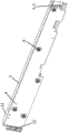
图1是本发明实施例CPU主板与硬盘背板互联装置的正面示意图;1 is a schematic front view of an interconnection device between a CPU motherboard and a hard disk backplane according to an embodiment of the present invention;
图2是本发明实施例CPU主板与硬盘背板互联装置的背面示意图;2 is a schematic diagram of the back of the interconnecting device between a CPU motherboard and a hard disk backplane according to an embodiment of the present invention;
图3是图1中连接侧板及侧板支架的正面结构示意图;Fig. 3 is the front structure schematic diagram of connecting side plate and side plate bracket in Fig. 1;
图4是图1中连接侧板及侧板支架的背面结构示意图;4 is a schematic diagram of the back structure of the connecting side plate and the side plate bracket in FIG. 1;
附图标记:Reference number:
1-硬盘背板,2-背板连接器,3-供电导向PIN,4-连接侧板,5-侧板支架,5-1抽牙螺丝孔,5-2加强凸包,6-六角平头螺丝,7-CPU板信号连接器,8-CPU板电源连接器,9-CPU板支架,10-CPU主板,11-侧板电源连接器,12-侧板信号连接器,13-圆头沉孔螺母,14-压铆螺母。1- Hard disk backplane, 2- Backplane connector, 3- Power supply guide PIN, 4- Connection side board, 5- Side board bracket, 5-1 Threaded screw hole, 5-2 Reinforcement convex hull, 6- Hexagon flat head Screw, 7-CPU board signal connector, 8-CPU board power connector, 9-CPU board bracket, 10-CPU motherboard, 11-side board power connector, 12-side board signal connector, 13-round head sink Hole Nut, 14-Riveting Nut.
具体实施方式Detailed ways
为了使本发明的目的、技术方案及优点更加清楚明白,以下结合附图及实施例,对本发明进行进一步详细说明。应当理解,此处所描述的具体实施例仅仅用以解释本发明,并不用于限定本发明。In order to make the objectives, technical solutions and advantages of the present invention clearer, the present invention will be further described in detail below with reference to the accompanying drawings and embodiments. It should be understood that the specific embodiments described herein are only used to explain the present invention, but not to limit the present invention.
如图1至图4所示,本实施例一种实现CPU主板与硬盘背板互联的装置,包括硬盘背板1、背板连接器2、供电导向PIN3、连接侧板4和CPU主板10。硬盘背板1为承载硬盘连接器、背板连接器2及供电导向PIN3的PCB板;背板连接器2固定在硬盘背板1上,与连接侧板上对应的连接器插接进行信号传输;1供电导向PIN3固定在硬盘背板1上,与连接侧板4上对应的连接器插接为CPU主板供电,同时在插接过程中对连接侧板的连接器起到导向作用,避免对插过程中发生倒PIN的现象;连接侧板4用于将硬盘背板与CPU主板连接在一起,实现两板之间的电流及信号传输;CPU主板为服务器的核心结构,其上安装有各类芯片及连接器。As shown in FIGS. 1 to 4 , a device for interconnecting a CPU motherboard and a hard disk backplane in this embodiment includes a
具体而言,如图1、图2所示,连接侧板的一端通过连接器与硬盘背板对插连接,连接侧板上与硬盘背板相连接的一端设置有侧板电源连接器11和侧板信号连接器12,侧板电源连接器11与硬盘背板1上的供电导向PIN3对插实现电流的传输,侧板信号连接器12与硬盘背板1上的背板连接器2对插实现信号的传输。供电导向PIN3与侧板电源连接器1对插时,对侧板信号连接器起到导向作用,对插完成后通过硬盘背板将电流经连接侧板导向CPU主板,并对CPU主板供电。连接侧板的另一端通过金手指与CPU主板10对插连接,CPU主板10上与连接侧板4相连接的一端设置有CPU板信号连接器7和CPU板电源连接器8,CPU板信号连接器7和CPU板电源连接器8与连接侧板4上的金手指对插连接,以实现电源的传输以及信号的传送,同时也实现了电源与信号之间的分开传输。Specifically, as shown in FIG. 1 and FIG. 2 , one end of the connection side plate is connected to the hard disk backplane through a connector, and the end of the connection side plate connected to the hard disk backplane is provided with a side plate power connector 11 and The side
如图3、图4所示,连接侧板4固定在侧板支架5上,侧板支架承载连接侧板。整个连接侧板4可通过六角平头螺丝6与压铆螺母14配合固定在侧板支架上。同时侧板支架5的背面设计有加强凸包5-2,以满足侧板支架的强度需求。As shown in FIG. 3 and FIG. 4 , the connecting
CPU主板10固定在CPU板支架9上,在侧板支架5的背面设有抽牙螺丝孔5-1,通过抽牙螺丝孔5-1与圆头沉孔螺母13的配合,将侧板支架5装配在CPU板支架9之上。The CPU
本实施例一种实现CPU主板与硬盘背板互联装置的使用方法,包括:In the present embodiment, a method for implementing a device for interconnecting a CPU motherboard and a hard disk backplane includes:
(1)将背板连接器2及供电导向PIN3固定在硬盘背板1上,并将硬盘背板连同其上安装的部件一起装配进服务器;(1) Fix the
(2)将侧板电源连接器11和侧板信号连接器12固定在连接侧板4上,然后将连接侧板4与其上安装的部件装配在侧板支架5上;(2) Fix the side panel power connector 11 and the side
(3)将CPU板信号连接器7和CPU板电源连接器8固定在CPU主板10上,然后将CPU主板10与其上安装的部件装配在CPU板支架9上;(3) The CPU board signal connector 7 and the CPU board
(4)将连接侧板4与CPU主板10对插,对插到位后,将侧板支架5装配在CPU板支架9上;(4) Insert the
(5)将CPU板支架9以及侧板支架5装入服务器,并将硬盘背板1与连接侧板4对应的连接器对插。(5) Install the
具体来说,在步骤(2)中,连接侧板通过压铆螺母14装配在侧板支架上5,然后通过六角平头螺丝6将连接侧板4及其连接器锁固在侧板支架5上。Specifically, in step (2), the connecting side plate is assembled on the
在步骤(4)中,在将侧板支架装配在CPU板支架9上的过程中,先将连接侧板4上的金手指与CPU主板10上的CPU板信号连接器7和CPU板电源连接器8对插,保证对插的位置,对插到位后,通过圆头沉孔螺母13与侧板支架5上抽牙螺丝孔5-1的配合,将侧板支架5连同连接侧板4装配在CPU板支架9上,实现CPU主板10与连接侧板4之间的对插。In step (4), in the process of assembling the side plate bracket on the
在步骤(5)中,在将CPU板支架9与侧板支架5装入服务器时,首先将硬盘背板1上的供电导向PIN3与连接侧板4上的侧板电源连接器11接触,在供电导向PIN3的导向作用下,保证背板连接器2与侧板信号连接器12之间对插时不会发生倒PIN的现象。CPU板支架9安装到位后,供电导向PIN3与侧板电源连接器11进行对插,背板连接器2与侧板信号连接器12进行对插。In step (5), when installing the
在拆卸时,根据上述所述步骤(1)至(5)逆向完成即可,即先将CPU板支架9拆卸,然后拆卸侧板支架5,最后进行连接侧板4拆卸。When disassembling, it can be done in reverse according to the above steps (1) to (5), that is, the
在本发明实施例中,将CPU主板与硬盘背板的连接通过PCB板及板上连接器间对插实现,避免了线缆的使用,并且可以实现热插拔维护,避免了繁复插拔线缆的过程。通过PCB板实现电流及信号的传输同时节省了空间,提高了服务器内部空间的利用率,而且这一设计方法在插拔过程中无需任何工具,操作方便。此外,该CPU主板与硬盘背板互联的装置方法固定牢固、可靠,且此结构方案的设计简洁,实现方便,可在硬盘背板与CPU主板互联中得到广泛的应用。In the embodiment of the present invention, the connection between the CPU motherboard and the hard disk backplane is realized by plugging between the PCB board and the on-board connectors, which avoids the use of cables, and can realize hot-plug maintenance and avoid complicated plugging and unplugging of cables. cable process. The transmission of current and signals is realized through the PCB board, which saves space and improves the utilization rate of the internal space of the server. Moreover, this design method does not require any tools during the plugging and unplugging process, and is easy to operate. In addition, the device method for interconnecting the CPU mainboard and the hard disk backplane is firm and reliable, and the structural scheme is simple in design and convenient in implementation, and can be widely used in the interconnection between the hard disk backplane and the CPU mainboard.
以上所述仅为本发明的较佳实施例而已,并不用以限定本发明,对于本技术领域的技术人员来说,在不脱离本发明原理的前提下所作的任何修改、改进和等同替换等,均包含在本发明的保护范围内。The above descriptions are only preferred embodiments of the present invention, and are not intended to limit the present invention. For those skilled in the art, any modifications, improvements and equivalent replacements made without departing from the principles of the present invention, etc. , are included in the protection scope of the present invention.
Claims (9)
Priority Applications (1)
| Application Number | Priority Date | Filing Date | Title |
|---|---|---|---|
| CN201710711097.0A CN107479657B (en) | 2017-08-18 | 2017-08-18 | Device for realizing interconnection of CPU mainboard and hard disk backplane and use method thereof |
Applications Claiming Priority (1)
| Application Number | Priority Date | Filing Date | Title |
|---|---|---|---|
| CN201710711097.0A CN107479657B (en) | 2017-08-18 | 2017-08-18 | Device for realizing interconnection of CPU mainboard and hard disk backplane and use method thereof |
Publications (2)
| Publication Number | Publication Date |
|---|---|
| CN107479657A CN107479657A (en) | 2017-12-15 |
| CN107479657B true CN107479657B (en) | 2020-08-25 |
Family
ID=60601550
Family Applications (1)
| Application Number | Title | Priority Date | Filing Date |
|---|---|---|---|
| CN201710711097.0A Active CN107479657B (en) | 2017-08-18 | 2017-08-18 | Device for realizing interconnection of CPU mainboard and hard disk backplane and use method thereof |
Country Status (1)
| Country | Link |
|---|---|
| CN (1) | CN107479657B (en) |
Families Citing this family (3)
| Publication number | Priority date | Publication date | Assignee | Title |
|---|---|---|---|---|
| CN109358710B (en) | 2018-09-25 | 2022-02-18 | 郑州云海信息技术有限公司 | Interconnection device and interconnection method of signal boards |
| CN113253263B (en) * | 2021-06-22 | 2021-10-15 | 湖南华诺星空电子技术有限公司 | A three-dimensional through-wall radar system |
| CN114661109B (en) * | 2022-03-25 | 2023-04-28 | 苏州浪潮智能科技有限公司 | Multipath cross-node signal interconnection structure |
Citations (6)
| Publication number | Priority date | Publication date | Assignee | Title |
|---|---|---|---|---|
| CN2704129Y (en) * | 2004-05-21 | 2005-06-08 | 展骏企业股份有限公司 | female connector |
| CN101930276A (en) * | 2010-08-30 | 2010-12-29 | 浪潮电子信息产业股份有限公司 | A method for realizing mainboard power supply through hot-swapping technology |
| CN204230532U (en) * | 2014-08-21 | 2015-03-25 | 英迪迈智能驱动技术无锡有限公司 | A kind of self-steering circuit board connector |
| CN105607193A (en) * | 2014-11-25 | 2016-05-25 | 深圳日海通讯技术股份有限公司 | Optical fiber connector plug and assembly method thereof |
| CN205353888U (en) * | 2015-12-30 | 2016-06-29 | 深圳市国鑫恒宇科技有限公司 | Cableless ization storage server |
| CN206147612U (en) * | 2016-08-05 | 2017-05-03 | 深圳中电长城信息安全系统有限公司 | Connecting circuit and computer |
-
2017
- 2017-08-18 CN CN201710711097.0A patent/CN107479657B/en active Active
Patent Citations (6)
| Publication number | Priority date | Publication date | Assignee | Title |
|---|---|---|---|---|
| CN2704129Y (en) * | 2004-05-21 | 2005-06-08 | 展骏企业股份有限公司 | female connector |
| CN101930276A (en) * | 2010-08-30 | 2010-12-29 | 浪潮电子信息产业股份有限公司 | A method for realizing mainboard power supply through hot-swapping technology |
| CN204230532U (en) * | 2014-08-21 | 2015-03-25 | 英迪迈智能驱动技术无锡有限公司 | A kind of self-steering circuit board connector |
| CN105607193A (en) * | 2014-11-25 | 2016-05-25 | 深圳日海通讯技术股份有限公司 | Optical fiber connector plug and assembly method thereof |
| CN205353888U (en) * | 2015-12-30 | 2016-06-29 | 深圳市国鑫恒宇科技有限公司 | Cableless ization storage server |
| CN206147612U (en) * | 2016-08-05 | 2017-05-03 | 深圳中电长城信息安全系统有限公司 | Connecting circuit and computer |
Also Published As
| Publication number | Publication date |
|---|---|
| CN107479657A (en) | 2017-12-15 |
Similar Documents
| Publication | Publication Date | Title |
|---|---|---|
| CN102129274A (en) | Server, server subassembly and fan speed control method | |
| CN209265434U (en) | A kind of 8 disk position NVMe hard disk backboards with off-peak electrification function | |
| CN204667289U (en) | A kind of server | |
| TW201321940A (en) | Riser card | |
| CN102455737B (en) | A blade type external expansion card module | |
| CN101739379B (en) | Server-based method for designing hot-swappable PCIE equipment box | |
| CN201171129Y (en) | Adapter | |
| CN204904151U (en) | Built -in switching card | |
| US20140146492A1 (en) | Power supply unit | |
| CN107479657A (en) | It is a kind of to realize cpu motherboard and the device and its application method of hard disk backboard interconnection | |
| CN106528469A (en) | Mainboard | |
| US20190095774A1 (en) | Modular ngsff module to meet different density and length requirements | |
| CN205353891U (en) | 4U does not have cable storage server | |
| US10923842B1 (en) | Systems and methods for signal integrity insertion loss minimization in input/output backplanes | |
| CN216817397U (en) | Backboard and conversion card | |
| CN205248533U (en) | Device is pulled out in helping of stromatolite connector | |
| US20210204437A1 (en) | Chassis internal connection structure for server | |
| CN203748164U (en) | Fixed structure and circuit board adapter | |
| CN209103234U (en) | A host that supports multiple GPUs in a 2U chassis | |
| CN108008764A (en) | Circuit board composition | |
| CN205353886U (en) | 3U does not have cable storage server | |
| CN205353889U (en) | Large capacity cableless 1U server | |
| WO2018072506A1 (en) | Assembling apparatus, use method thereof, and assembling system | |
| CN209543274U (en) | A four-way server power board | |
| CN211506475U (en) | A connection device for OCP network card mutil-host |
Legal Events
| Date | Code | Title | Description |
|---|---|---|---|
| PB01 | Publication | ||
| PB01 | Publication | ||
| SE01 | Entry into force of request for substantive examination | ||
| SE01 | Entry into force of request for substantive examination | ||
| TA01 | Transfer of patent application right |
Effective date of registration: 20200724 Address after: 215100 No. 1 Guanpu Road, Guoxiang Street, Wuzhong Economic Development Zone, Suzhou City, Jiangsu Province Applicant after: SUZHOU LANGCHAO INTELLIGENT TECHNOLOGY Co.,Ltd. Address before: 450018 Henan province Zheng Dong New District of Zhengzhou City Xinyi Road No. 278 16 floor room 1601 Applicant before: ZHENGZHOU YUNHAI INFORMATION TECHNOLOGY Co.,Ltd. |
|
| TA01 | Transfer of patent application right | ||
| GR01 | Patent grant | ||
| GR01 | Patent grant | ||
| CP03 | Change of name, title or address |
Address after: Building 9, No.1, guanpu Road, Guoxiang street, Wuzhong Economic Development Zone, Wuzhong District, Suzhou City, Jiangsu Province Patentee after: Suzhou Yuannao Intelligent Technology Co.,Ltd. Country or region after: China Address before: Building 9, No.1, guanpu Road, Guoxiang street, Wuzhong Economic Development Zone, Wuzhong District, Suzhou City, Jiangsu Province Patentee before: SUZHOU LANGCHAO INTELLIGENT TECHNOLOGY Co.,Ltd. Country or region before: China |
|
| CP03 | Change of name, title or address |